Cosmo COS-3012ORLP1SS User manual

MICROWAVE OVEN
COS-3012ORLP1SS
INSTALLATION INSTRUCTIONS
READ AND SAVE THESE INSTRUCTIONS.
FOR RESIDENTIAL USE ONLY.
PLEASE LEAVE THESE INSTRUCTIONS WITH THIS UNIT FOR
THE OWNER.
PLEASE RETAIN THESE INSTRUCTIONS FOR FUTURE
REFERENCE.
IMPORTANT:
INSTALLER:
OWNER:
OVER THE RANGE LOW PROFILE
MICROWAVE OVEN
Rev. 22.10

1
THANK YOU FOR YOUR PURCHASE
Thank you for your purchase. We know that you have many brands and
products to choose from and we are honored to know that you have decided
to take one of our products into your home and hope that you enjoy it.
COSMO Appliances are designed according to the strictest safety and
performance standard for the North American market. We follow the most
advanced manufacturing philosophy. Each appliance leaves the factory after
thorough quality inspection and testing. Our distributors and our service
partners are ready to answer any questions you may have regarding how to
install, use and case for your products. We hope that this manual will help you
learn to use the product in the safest and most effective manner.
Before using this product, please read through this manual carefully. Keep
this user manual in a safe place for future reference. Please ensure that other
persons using this product are familiar with these instructions as well.
If you have any questions or concerns, please contact the dealer from whom you
purchased the product, or contact our Customer Support at:
1-888-784-3108
Reach us online at:
www.cosmoappliances.com

2
TABLE OF CONTENTS
MICROWAVE OVEN SAFETY............................................................................... 4
INSTALLATION REQUIREMENTS ........................................................................ 5
Tools and Parts .......................................................................................................... 5
Location Requirements ............................................................................................ 7
Product Dimensions .................................................................................................. 8
Installation Dimensions............................................................................................ 9
Electrical Requirements.......................................................................................... 10
INSTALLATION INSTRUCTIONS......................................................................... 12
Unpack Microwave Oven ....................................................................................... 13
Prepare Location ......................................................................................................14
Locate Wall Stud(s) .............................................................................................14
Determine Wall Mounting Plate Location ......................................................15
Drill Wall Mounting Plate Screw Holes............................................................ 18
Install Microwave Oven ..........................................................................................19
For Recirculating (Ductless, Non-Vented) Only .............................................19
Attach Wall Mounting Plate .......................................................................19
Prepare Top Cabinet ...................................................................................20
Adjust Microwave Oven Blower ................................................................ 22
Install the Microwave Oven ....................................................................... 23
Replace Charcoal Filters ............................................................................. 24
For Top Venting (Ducted, Roof/Vertical Venting) Only............................... 25
Attach Wall Mounting Plate ...................................................................... 25
Prepare Top Cabinet ................................................................................... 26
Adjust Microwave Oven Blower ................................................................ 29
Install the Microwave Oven ........................................................................ 31
Connect Ductwork ....................................................................................... 32

3
For Rear Venting (Ducted, Wall/Horizontal Venting) Only ........................ 33
Attach Wall Mounting Plate ...................................................................... 33
Prepare Top Cabinet ................................................................................... 35
Adjust Microwave Oven Blower ................................................................ 37
Install the Microwave Oven ....................................................................... 39
Complete Installation..............................................................................................41
VENTING DESIGN SPECIFICATIONS ................................................................. 43

4
MICROWAVE OVEN SAFETY
Your safety and the safety of others are very important.
We have provided many important safety messages in this manual and on
your appliance. Always read and obey all safety messages.
This is the safety alert symbol.
This symbol alerts you to potential hazards that can
kill or hurt you and others.
All safety messages will follow the safety alert symbol
and either the word "DANGER" or "WARNING."
These words mean:
DANGER You can be killed or seriously
injured if you don't immediately
follow instructions.
You can be killed or seriously
injured if you don't follow
instructions.
WARNING
All safety messages will tell you what the potential hazard is, tell you how
to reduce the chance of injury, and tell you what can happen if the
instructions are not followed.

5
INSTALLATION REQUIREMENTS
TOOLS AND PARTS
Gather the required tools and parts before starting installation. Read and
follow the instructions provided with any tools listed here.
Tools Needed
•Measuring tape
•Pencil
•Masking tape or thumbtacks
•Scissors
•#1 Phillips screwdriver
•Drill
•Drill bits
•Hole saw
•Diagonal wire cutting pliers
•Stud finder
•Socket wrench
•Hole drill bit for cabinet
•Keyhole saw
•Caulking gun and weatherproof
caulking compound
•Duct tape
Parts Supplied
Grease filters (2) Glass turntable (1) Turntable rollers (1)
Exhaust adapter (1) Top cabinet mounting template
(1)
Rear wall mounting template
(1)

6
Hardware Supplied
1/4" x 2" wood screws (2) 3/16" x 3" toggle bolts with wing
nuts (2)
1/4"-28 x 31/4" self-aligning screws
(3)
Nylon grommet (1)
–for metal cabinets-
NOTE: Some extra parts are included.
Materials Needed
•Standard fittings for wall or roof venting. See the "Venting Design
Specifications" section.
Optional Parts
To purchase these or any other accessories, please visit
www.cosmoappliances.com or reference the contact information at the end
of this manual.
Replacement charcoal filters (2) Replacement grease filters (2) Replacement glass turntable and
rollers (1 set)

7
LOCATION REQUIREMENTS
IMPORTANT: Check the opening where the microwave oven will be installed.
The location must provide:
•The unit must be mounted to both a top cabinet and a wall. It cannot be
installed in cabinet arrangements such as an island or a peninsula.
•Minimum installation dimensions. See the "Installation Dimensions"
illustration.
•Minimum one 2" x 4" (50.8 x 101.6 mm) wood wall stud and minimum 3/8"
(10 mm) thickness drywall or plaster/lath within cabinet opening.
•Support for weight of 150 lbs (68 kg) which includes microwave oven and
items placed inside the microwave oven and upper cabinet.
•Grounded electrical outlet inside upper cabinet. See the "Electrical
Requirements" section.
NOTES:
•If installing the microwave oven near a left sidewall, make sure there is at
least 6" (15.2 cm) of clearance between the wall and the microwave oven
so that the door can open fully.
•Some cabinet and building materials are not designed to withstand the
heat produced by the microwave oven for cooking. Check with your
builder or cabinet supplier to make sure that the materials used will not
discolor, delaminate, or sustain other damages.
SPECIAL REQUIREMENTS
For Wall Venting Installation Only:
•Cutout must be free of any obstructions so that the vent fits properly and
the damper blade opens freely and fully.
For Roof Venting Installation Only:
•If you are using a rectangular-to-round transition piece, the 3" (7.6 cm)
clearance needs to exist above the microwave oven so that the damper
blade can open freely and fully.
8
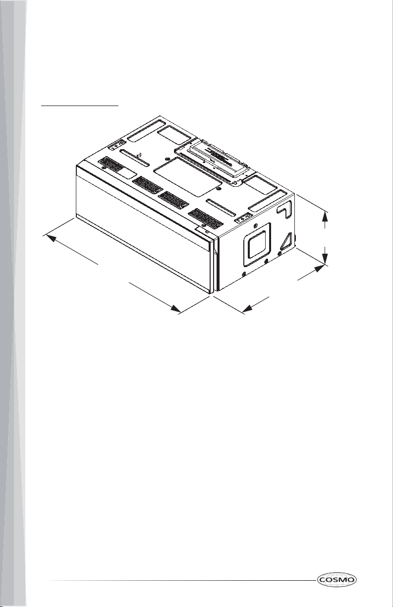
PRODUCT DIMENSIONS
NOTE: Overall depth of product will vary slightly depending on door design.
COS-3012ORLP1SS
29 ⁷⁄₈"
(759 mm) 18 ⁹⁄₁₆"
(471mm)
10 ⁵⁄₁₆"
(262 mm)
9
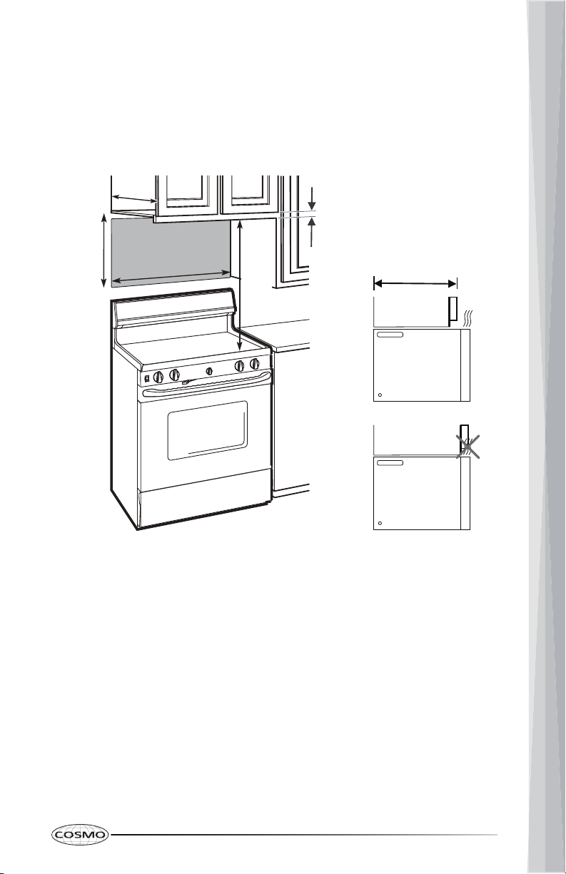
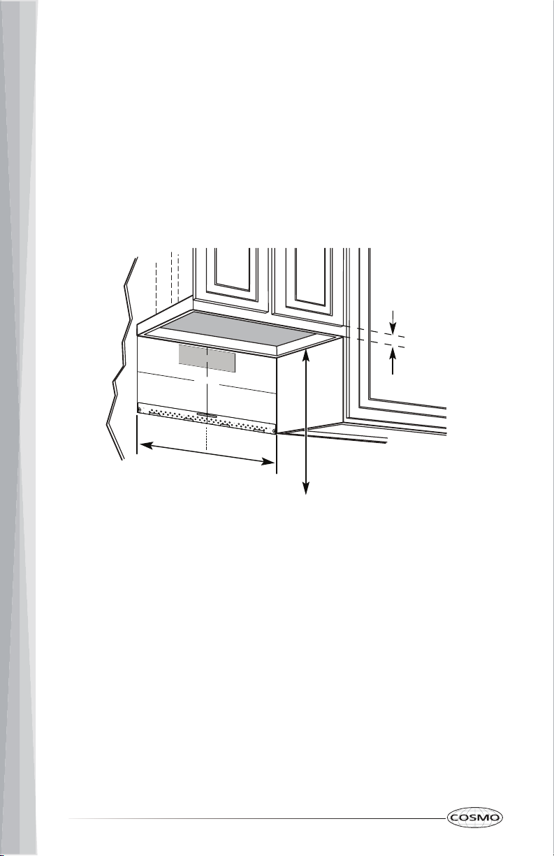
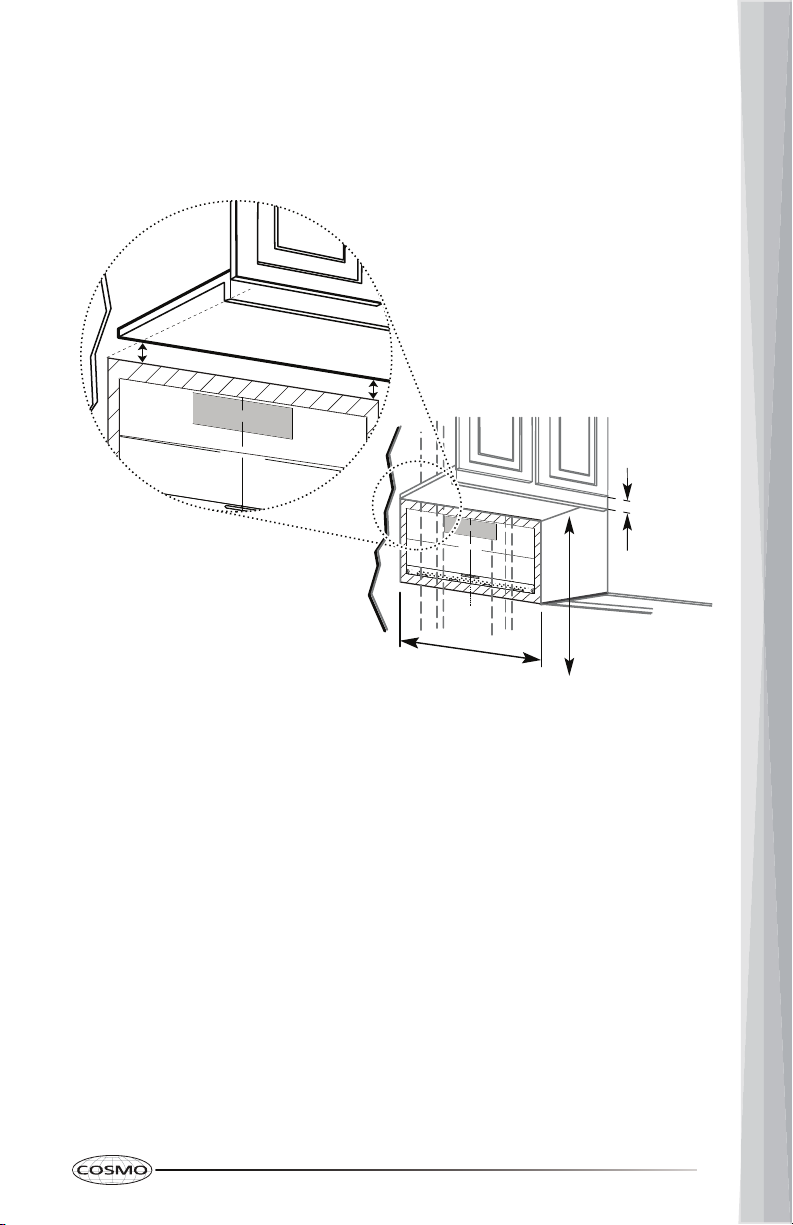
INSTALLATION DIMENSIONS
NOTE: The grounded 3 prong outlet must be inside the upper cabinet. See the
"Electrical Requirements" section.
NOTE:
•24" (61 cm) top cabinet clearance is typical for 60" (152.4 cm) installation
height from the floor. Exact dimensions may vary depending on type of
range/cooktop below.
•To ensure good performance, do not obstruct top vent airflow. If top
cabinets are deeper than 13.8" (35 cm), the unit must be spaced out from
the wall using adequate materials supporting 150 lbs.
10.3 in
(26.2 cm)
Max.
13.8 in
(35 cm)
Min.
24 in
(61 cm)
30 in
(76.2 cm)
Min.
¹/₄ in
(0.64 cm)
Clearance
Cabinet
Front
Microwave
Oven
Max.
13.8 in
(35 cm)
Cabinet
Front
Microwave
Oven
10
ELECTRICAL REQUIREMENTS
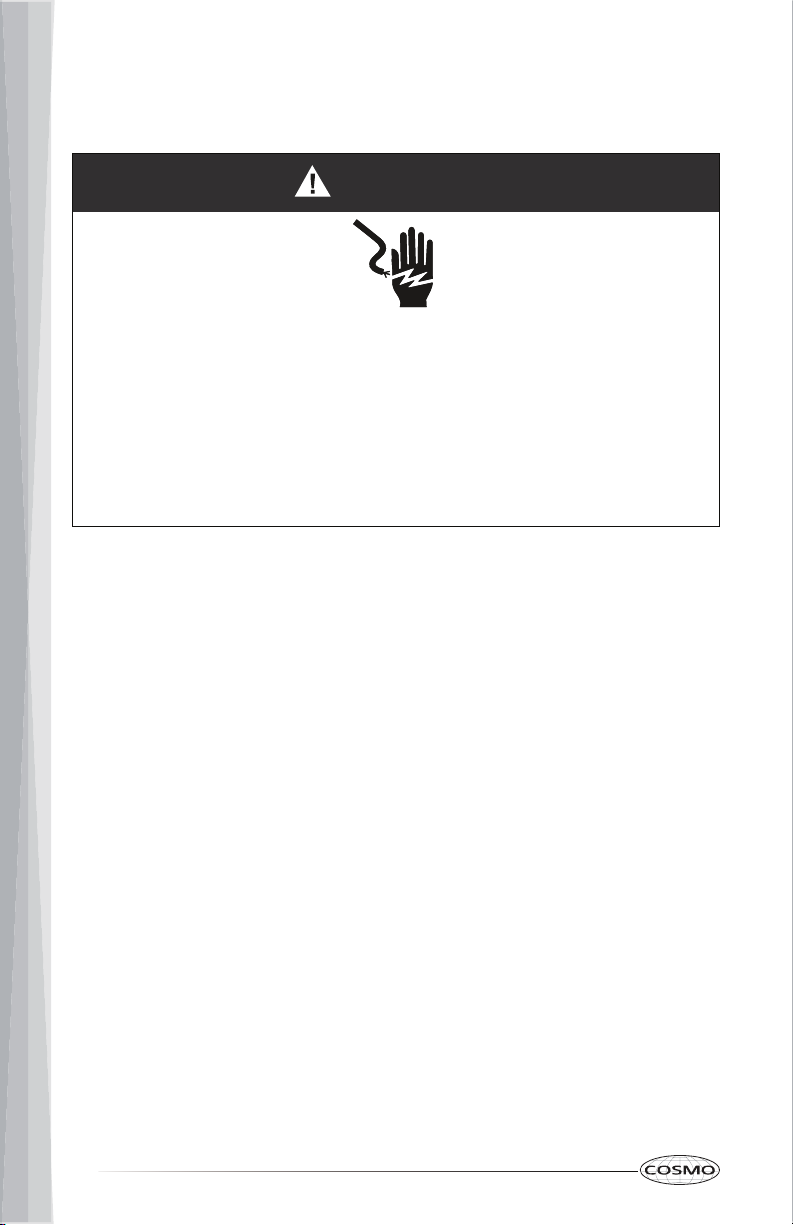
WARNING
Electrical Shock Hazard
Plug into a grounded 3 prong outlet.
Do not remove ground prong.
Do not use an adapter.
Do not use an extension cord.
Failure to following these instructions can result in death, fire, or electrical
shock.
Observe all governing codes and ordinances.
Product rating:
Required:
•A 120 V, 60 Hz, AC only, 15 or 20 A electrical supply with a fuse or circuit
breaker.
Recommended:
•A time-delay fuse or time-delay circuit breaker.
•A separate circuit serving only this microwave oven.
This product must be connected to a separate and dedicated supply circuit of
the proper voltage and frequency. Wire size must conform to the
requirements of the National Electrical Code or the prevailing local code for
this kilowatt rating.
The power supply cord and plug should be brought to a separate and
dedicated 15- to 20- ampere branch circuit single grounded outlet. The outlet
box should be located in the cabinet above the microwave oven.
The outlet box and supply circuit should be installed by a qualified electrician
and conform to the National Electrical Code or the prevailing local code.
•A 120 V AC, 60 Hz, 15 A, 1550 W.

11
The installer must perform a ground continuity check on the power outlet box
before beginning the installation to ensure that the outlet box is properly
grounded. A qualified electrician should be employed to correct any
deficiencies.
GROUNDING INSTRUCTIONS
For all cord connected appliances:
•The microwave oven must be grounded. In the event of an electrical short
circuit, grounding reduces the risk of electric shock by providing an
escape wire for the electric current.
•The microwave oven is equipped with a cord having a grounding wire
with a grounding plug. The plug must be plugged into an outlet that is
properly installed and grounded.
•Where a standard two-prong wall receptacle is encountered, have it
replaced with a properly grounded three-prong wall receptacle by a
qualified electrician.
WARNING:
•Do not, under any circumstances, cut, deform, or remove any of the
prongs from the power cord.
•Improper use of the grounding plug can result in a risk of electric shock.
Consult a qualified electrician or serviceman if the grounding instructions
are not completely understood, or if doubt exists as to whether the
microwave oven is properly grounded.
•Do not use an extension cord. If the power supply cord is too short, have a
qualified electrician or serviceman install an outlet near the microwave
oven.
12
INSTALLATION INSTRUCTIONS
IMPORTANT: This appliance shall be installed only by authorized persons and
in accordance with the manufacturer's installation instructions, local gas
fitting regulations, municipal building codes, electrical wiring regulations,
local water supply regulations.
This microwave oven is designed for adaptation to the following types of
ventilation:
•Recirculating
(Ductless, Non-Vented)
•Top Venting
(Ducted, Roof/Vertical Venting)
•Rear Venting
(Ducted, Wall/Horizontal Venting)
Please follow the instructions provided for your type of ventilation.
13
UNPACK MICROWAVE OVEN
WARNING
Excessive Weight Hazard
Use two or more people to move and install microwave oven.
Failure to do so can result in back or other injury.
IMPORTANT: To avoid damage to the microwave oven, do not grip or use the
door or door handle while the microwave oven is being handled.
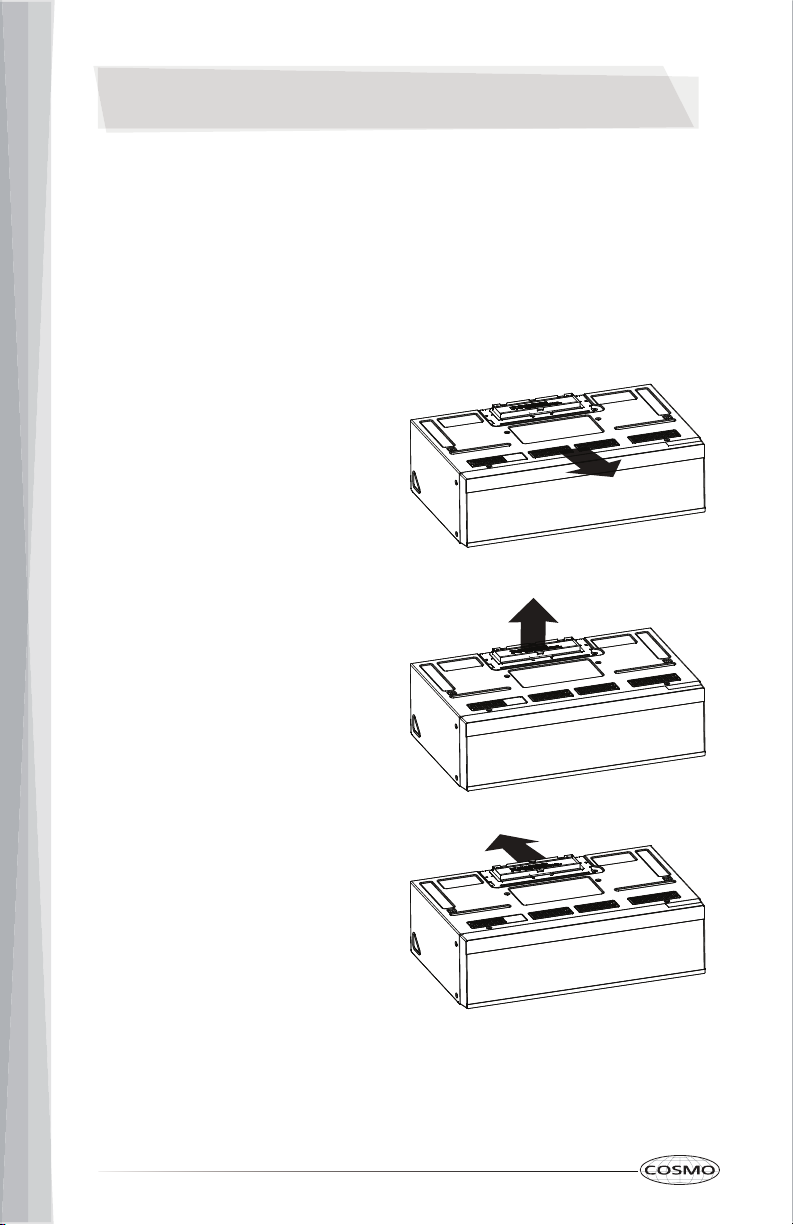
1. Open the top of the carton, and remove all the parts stored in the top
Styrofoam.
NOTE: Keep the plastic protective plug cover on until hanging the unit.
2. With the top Styrofoam still in place, fully fold back all carton flaps and
carefully roll the microwave oven and carton over onto the top side.
3. Lift up and remove the carton from the microwave oven.
Exhaust Adapter
Small Hardware Bag
Glass Turntable
Turntable Roller
Grease Filters
Carton
Microwave Oven
Styrofoam
14
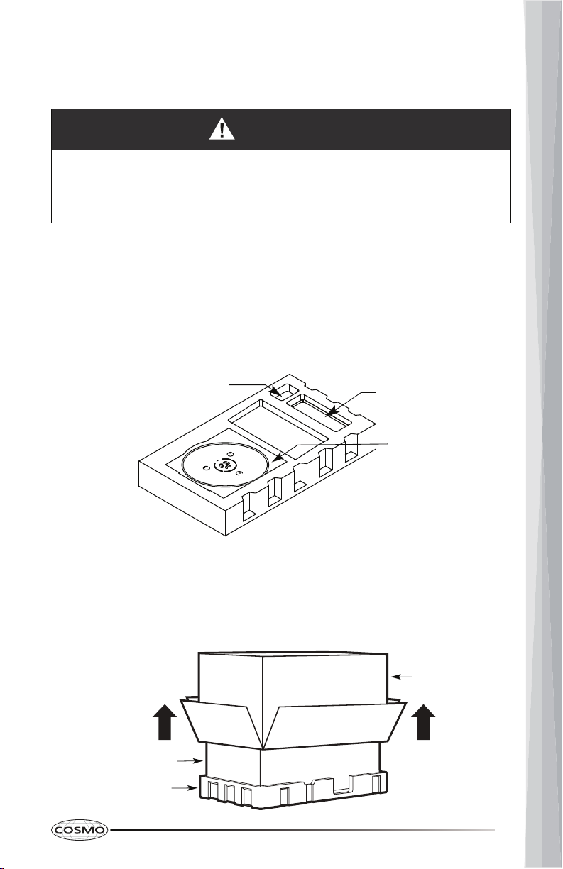
4. Remove the bottom Styrofoam that is now on the top of the microwave
oven, then remove or cut open the protective plastic bag.
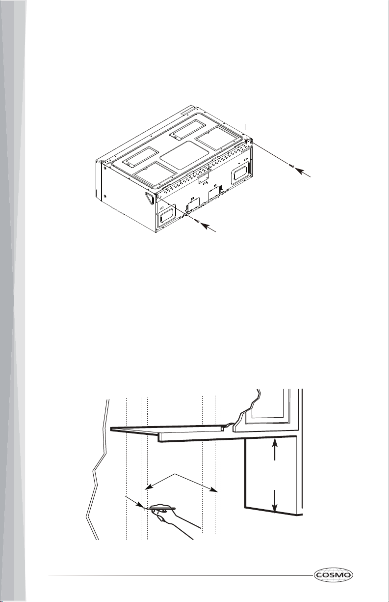
5. Detach the rear wall mounting plate by removing the screws from each
end of the plate, then reinstall the screws back.
PREPARE LOCATION
LOCATE THE WALL STUDS
IMPORTANT:
•The microwave oven must be mounted on at least one wall stud.
•If no wall studs exist within the 30" installation space in the cabinet
opening, do not install the microwave oven.
Screw
Mounting Plate
Screw
Wall
Studs
Center
10.3 in
(26.2 cm)
15
1. Using a stud finder, locate the edges of the wall stud(s) within the 30"
installation space.
NOTE: The center of any adjacent wall studs should be 16" (40.6 cm) or
24" (61 cm) from another.
2. Mark the center of each stud near the bottom of the installation space
and draw a plumb line down each stud center.
DETERMINE WALL MOUNTING PLATE LOCATION
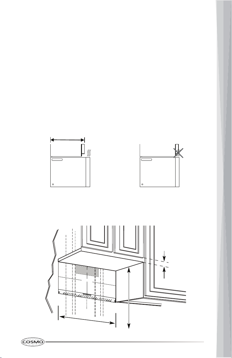
IMPORTANT:
•If top cabinets are deeper than 13.8" (35 cm), the unit must be spaced out
from the wall using adequate materials supporting 150 lbs to allow top
vent airflow in the front. These materials are not provided.
•Before positioning the Rear Wall Mounting Template, use a level to make
sure the cabinet bottom is level.
For Cabinet with Flat Bottom:
Max. 13.8 in (35 cm)
Cabinet
Front
Cabinet
Front
1/4 in
Minimum
Clearance
At least 30 in
Minimum
24 in Clearance
to Cooktop
16
1. Draw a vertical line on the wall at the center of the 30" installation space.
2. Position and tape the Rear Wall Mounting Template on the wall with the
vertical center line on the template and the vertical center line on the wall
aligned and the template in contact and level with the bottom of the
cabinet.
NOTE: Make sure the plumb line of the each stud center is visible just
below the template before taping the template to the wall.
For Cabinet with Recessed Bottom:
1. Draw a vertical line on the wall at the center of the 30" installation space.
2. Position and tape the Rear Wall Mounting Template on the wall with the
vertical center line on the template and the vertical center line on the wall
aligned and the template in contact and level with the bottom of the
cabinet.
NOTE: Make sure the plumb line of the each stud center is visible below
the template before taping the template to the wall.
At least 30 in
1/4 in
Minimum
Clearance
Minimum
24 in Clearance
to Cooktop
17
For Cabinet with Front Overhang or Decorative Trim:
Some cabinets may have decorative trim that interferes with the microwave
oven installation. Remove the decorative trim to level and install the
microwave oven properly.
1. Draw a vertical line on the wall at the center of the 30" installation space.
2. Measure the inside depth of the front overhang.
3. Draw a horizontal line on the back wall at equal distance as the inside
depth of the front overhang below the cabinet bottom.
4. Position and tape the Rear Wall Mounting Template on the wall with the
vertical center line on the template and the vertical center line on the wall
aligned and the top edge of the template in contact and level with the
horizontal line drawn.
NOTE: Make sure the plumb line of the each stud center is visible below
the template before taping the template to the wall.
At least 30 in
1/4 in
Minimum
Clearance
Minimum
24 in Clearance
to Cooktop

18
DRILL WALL MOUNTING PLATE SCREW HOLES
1. Draw a horizontal line on the wall at the bottom edge of Rear Wall
Mounting Template.
2. Using the plumb line of each stud center drawn earlier, find and mark the
hole closest to each stud center at the bottom of the template.
NOTE: At least one wood screw must be mounted firmly in a stud to
support the weight of the microwave oven.
3. If only one wall stud hole exists within the template, mark 2 additional
toggle bolt holes that are evenly spaced from the center line of the
template. For examples, mark holes labelled A and B on the template for
toggle bolts if none of them is in a stud.
Horizontal Line
Vertical
Center Line
A
B
Other manuals for COS-3012ORLP1SS
1
Table of contents
Other Cosmo Microwave Oven manuals

Cosmo
Cosmo COS-12MWDSS User manual

Cosmo
Cosmo COS-12MWDSS User manual

Cosmo
Cosmo COS-3016ORM1SS User manual

Cosmo
Cosmo COS-MWD3012GSS User manual

Cosmo
Cosmo COS-3016ORM1SS User manual

Cosmo
Cosmo COS-BIM22SSB User manual

Cosmo
Cosmo COS-2413ORM1SS User manual

Cosmo
Cosmo COS-07CTMSSB User manual

Cosmo
Cosmo COS-MWD3012GSS User manual

Cosmo
Cosmo COS-3019ORM2SS User manual


