Cosmo COS-2413ORM1SS User manual
IMPORTANT SAFETY INSTRUCTIONS
Carefully read the following Important information regarding installation
safety and maintenance. Keep these instruction for future reference.
I N S P I R I N G T H E W O R L D ’ S K I T C H E N
OVER THE RANGE
MICROWAVE
COS-2413ORM1SS
COS-2413ORM1SS INSTALL GUIDE

2 3
THANK YOU FOR YOUR PURCHASE
Thank you for your purchase. We know that you have many brands and
products to choose from and we are honored to know that you have decided
to take one of our products into your home and hope that you enjoy it.
COSMO appliances are designed according to the strictest safety and performance
standard for the North American market. We follow the most advanced
manufacturing philosophy. Each appliance leaves the factory after thorough
quality inspection and testing. Our distributors and our service partners are
ready to answer any questions you may have regarding how to install, use and
care for your products. We hope that this manual will help you learn to use the
product in the safest and most effective manner .
If you have any questions or concerns, please contact the dealer from whom you
purchased it, or contact our Customer Support at:
1-888-784-3108.
Specifications
Model:
Rated Voltage:
Rated Input Power(Microwave):
Rated Output Power(Microwave):
Oven Capacity:
Turntable Diameter:
External Dimensions:
Net Weight:
Approx.
120V~60Hz
COS-2413ORM1SS
1550W
1000W
1.34 cubic feet
21"
37" x 25" x 26.4"
57.3 lbs
Before You Use Your Microwave
CONTENTS
General information
Important Safety Instructions .................................. 3
Electrical Requirements .......................................... 3
Damage – Shipment/Installation.............................. 4
Parts Included.......................................................... 4
Tools You Will Need ................................................ 5
Mounting Space ...................................................... 5
Step-by-step installation guide
6–8
Removing the Mounting Plate ...................... 6
Finding the Wall Studs.................................. 6
Determining Wall Plate Location.................. 7
Aligning the Wall Plate ................................ 8
Outside Top Exhaust
Attach Mounting Plate to Wall............12
Preparation of Top Cabinet................13
Checking for Proper Damper
Adapting Microwave Blower
A
B
C
21
20
20
Recirculating ........................................
Mount the Microwave Oven ................19
Preparation of Top Cabinet ................17
Attach Mounting Plate to Wall ............17
Outside Back Exhaust..........................16
Connecting Ductwork..........................15
Adjust the Exhaust Adaptor ................15
Operation............................................14
Outside Back Exhaust............................ 16–19
Adapting Microwave Blower for
Outside top Exhaust .......... 13–14........
Placement of The Mounting Plate ......................
............................ 12–15
Preparing Rear Wall for
Remove Blower Plate ...................... 16...... ..
Charcoal Filter
Installing or Change the
22
Preparation of Top Cabinet ................2
Check Blower Plate ............................
.......................... 25
....................................22
Attach Mounting Plate to Wall ............
22
–
Installation Types............................................... 9–22
for Outside Back Exhaust................17 18
–
Mount the Microwave Oven ..........21–
Hood Exhaust.................................................. 10 11
–
Mount the Microwave Oven ..........14 15
–
.......................... 2Template Information...................
1
6

4 5
This product requires a three-prong grounded outlet.
The installer must perform a ground continuity check
on the power outlet box before beginning the
installation to ensure that the outlet box is properly
grounded. If not properly grounded, or if the outlet
box does not meet electrical requirements noted
(under ELECTRICAL REQUIREMENTS), a qualified
electrician should be employed to correct any
deficiencies. CAUTION: For personal
safety, remove house fuse
or open circuit breaker
before beginning
installation to avoid severe
or fatal shock injury.
CAUTION: For personal safety, the mounting surface
must be capable of supporting the cabinet load, in
addition to the added weight of this 63–85 pound
(28.5–38.5 kg) product, plus additional oven loads of
up to 50 pounds (22.7 kg) or a total weight of
113–135 pounds (51.3–61.2 kg).
CAUTION: For personal safety, this product cannot
be installed in cabinet arrangements such as an island or
a peninsula. It must be mounted to BOTH a top cabinet
AND a wall.
NOTE: For easier installation and personal safety, it is
recommended that two people install this product.
IMPORTANT – PLEASE READ CAREFULLY. FOR
PERSONAL SAFETY, THIS APPLIANCE MUST BE
PROPERLY GROUNDED TO AVOID SEVERE OR
FATAL SHOCK.
The power cord of this
appliance is equipped with a
three-prong (grounding)
plug which mates with a
standard three-prong
(grounding) wall receptacle
to minimize the possibility
of electric shock hazard
from this appliance.
You should have the wall receptacle and circuit checked
by a qualified electrician to make sure the receptacle is
properly grounded.
Where a standard two-prong wall receptacle is
encountered, it is very important to have it replaced
with a properly grounded three-prong wall receptacle,
installed by a qualified electrician.
DO NOT, UNDER ANY CIRCUMSTANCES, CUT,
DEFORM OR REMOVE ANY OF THE PRONGS
FROM THE POWER CORD. DO NOT USE WITH
AN EXTENSION CORD.
IMPORTANT SAFETY INSTRUCTIONS
Ensure proper
ground exists
before use
Installation Instructions
ELECTRICAL
REQUIREMENTS
Product rating is 120 volts AC, 60 Hertz, 15 amps and
1.6 kilowatts. This product must be connected to a
The power supply cord and plug should be brought to a
the prevailing local code for this kilowatt rating.
the requirements of the National Electrical Code or
voltage and frequency. Wire size must conform to
seperate and dedicated supply circuit of the proper
seperate and dedicated 15- to 20- ampere branch
National Electrical Code or the prevailing local code.
by a qualifed electrician and conform to the
The outler box and supply circuit should be installed
be located in the cabinet above the microwave oven.
circuit single grounded outlet. The outlet box should
PART QUANTITY
Wood Screws 2
(1⁄4“ x 2“)
Toggle Bolts (and
wing nuts) (3⁄16“ x 3“)
Self-Aligning Machine 3
Screws (1⁄4“-28 x 31⁄4“)
Nylon Grommet
(for metal cabinets) 1
•If the unit is damaged in shipment, return the
unit to the store in which it was bought for repair
or replacement.
•If the unit is damaged by the customer, repair or
replacement is the responsibility of the customer.
•If the unit is damaged by the installer (if other
than the customer), repair or replacement must
be made by arrangement between customer
and installer.
DAMAGE—SHIPMENT/
INSTALLATION
Installation Instructions
PARTS INCLUDED
You will find the installation hardware contained in
a packet with the unit. Check to make sure you have
all these parts.
NOTE: Some extra parts are included.
HARDWARE PACKET
PART
QUANTITY
Template 1
Template
Installation
1
Instructions
Separately
2
Packed
Filters
PARTS INCLUDED (CONT.)
INSTALLATION
INSTRUCTIONS
ADDITIONAL PARTS
1
adaptor
Grease
Exhaust
Glass
1
Tray
1
Ring
T ru ntable
CabinetTop
Rear Wall
2
1
Use & Care
1
USE & CARE
MANUAL
Manual

6 7
TOOLS YOU WILL NEED
# 1 Phillips screwdriver Pencil Ruler or tape measure and
straight edge Carpenter square
(optional)
Tin snips (for cutting
damper, if required) Electric drill with 3⁄16“, 1⁄2“and 5⁄8“
drill bits
Hammer (optional)
Stud finder or
Filler blocks or scrap
wood pieces, if needed
for top cabinet spacing
(used on recessed bottom
cabinet installations only)
Gloves
Saw (saber, hole or keyhole)
Level Duct and masking tape
Installation Instructions
Scissors
(to cut template, if necessary)
Safety goggles
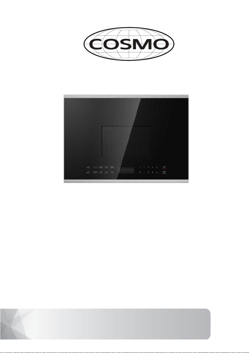
MOUNTING SPACE NOTES:
•The space between the cabinets must be
(61.0cm)wide and free of obstructions.
•If you are going to vent your microwave oven
to the outside, see Hood Exhaust Section for
exhaust duct preparation.
•When installing the microwave oven beneath
smooth, flat cabinets, be careful to follow the
instructions on the top cabinet template for
power cord clearance.
Bottom Edge of
Cabinet Needs to
be
or More from the
Cooking Surface
Backsplash
66w(167.6 cm)
or More from
the Floor to the
Topofthe
Microwave
2“ (5.1 cm)
30“
(76.2 cm)
min.
161⁄2“(41.9 cm)
13 Maximum (33 cm)
“
As a guide to installation, see page 24 for Mounting
Template Information.
•
•
Cabinet
Cabinet
If the cabinet depth including the cabinet doors
is more th n 13'""' th n the unit must be spaced
out from wall using adequate materials supporting
150 Ibs to allow proper top vent air exhaust/intake.
a e
24“(61.0cm)
24“
" (76.2 cm)
"
30
PLACEMENT OF THE MOUNTING PLATE
1
Installation Instructions
Find the studs, using one of the following
methods:
A. Stud finder – a magnetic device which
locates nails.
B. Use a hammer to tap lightly across the
mounting surface to find a solid sound.
This will indicate a stud location.
After locating the stud(s), find the center by
probing the wall with a small nail to find the edges
of the stud. Then place a mark halfway between
the edges. The center of any adjacent studs should
be 16w(40.6 cm) or 24w(61 cm) from this mark.
Draw a line down the center of the studs.
THE MICROWAVE MUST BE CONNECTED TO
AT LEAST ONE WALL STUD.
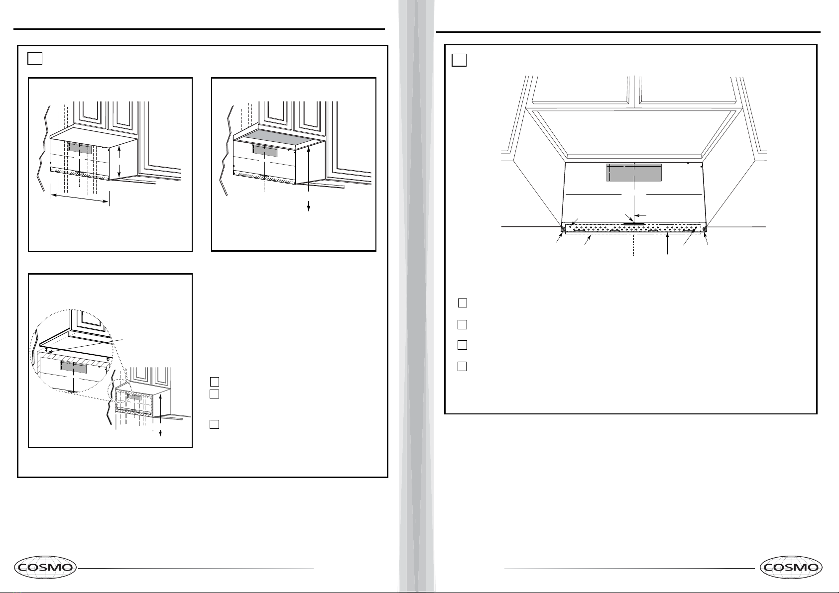
1
Fold back all 4 carton flaps fully against carton
sides. Then carefully roll the oven and carton over
onto the top side. The oven should be resting in
the Styrofoam.
REMOVING THE MICROWAVE
OVEN FROM THE CARTON/
REMOVING THE MOUNTING
PLATE
FINDING THE WALL STUDS
B.
A.
2
Wall
Studs
Center
3
Carton
Pull the carton up and off the oven.
2
Styrofoam
3
1
Screws Screws
Mounting Plate
5
4Cut the middle of the outer protective plastic bag to
remove the ounting late
mp
Filters and Turntable
Ring below glass tray
Exhaust Adapter
Small Hardware Bag
Glass Tray
Shelf ( For some
Remove the installation instructions,use and care,
exhaust adapter, turntable ring, shelf, filters, glass
Do notremove
the Styrofoam protecting the front of the oven.
Remove the screws from each end of the mounting
plate. This plate will be used as the rear wall template
bag.
and for mounting. Reinstall the screws into the holes
where they were removed.
tray and the small hardware
models)
8 9
DETERMINING WALL PLATE LOCATION UNDER YOUR CABINET
C.
Installation Instructions
Plate position flat bottom
cabinet
Draw a line on the
back wall equal to the
depth of the front
overhang.
to Cooktop
C
3/8"TOEDGE
NOTE:ITISVERYIMPORTANTTO
READANDFOLLOWTHEDIRECTIONS
INTHEINSTALLATIONINSTRUCTIONS
BEFOREPROCEEDINGWITHTHIS
REARWALLTEMPLATE.
ThisRearWallTemplateservestopositionthebottom
mountingplateandtolocatethehorizontalexhaust
outlet.
1.Usealeveltocheckthatthetemplateispositioned
accurately.
2.Locateandmarkatleastonestudontheleftor
rightsideofthecenterline.
Itisimportanttouseatleastonewood
screwmountedfirmlyinastudtosupporttheweight
ofthemicrowave.Marktwoadditional,evenlyspaced
locationsforthesuppliedtogglebolts.
3.Drillholesinthemarkedlocations.Wherethereis
astud,drilla 3/16"hole for woodscrews.Forholes
thatdonotlineupwithastud,drill5/8"holesfor
togglebolts.
DONOTINSTALLTHEMOUNTINGPLATE
ATTHISTIME.
4.Removethetemplatefromtherearwall.
5.ReviewtheInstallationInstructionbookforyour
installationsituation.
Locateandmarkholestoalignwithholesinthe
mountingplate.
IMPORTANT:
LOCATEATLEASTONESTUDONEITHERSIDEOF
THECENTERLINE.
MARKTHELOCATIONFOR2ADDITIONAL,EVENLY
SPACEDTOGGLEBOLTSINTHEMOUNTINGPLATE
AREA.
Locateandmarkholestoalignwithholesinthe
mountingplate.
IMPORTANT:
LOCATEATLEASTONESTUDONEITHERSIDEOF
THECENTERLINE.
MARKTHELOCATIONFOR2ADDITIONAL,EVENLY
SPACEDTOGGLEBOLTSINTHEMOUNTINGPLATE
AREA.
Trimtherearwalltemplatealongthedottedline.
Trimtherearwalltemplatealongthedottedline.
12"
4"
Darlevueltaalahojaparaconsultarla
versiónenEspañol.
3/8"TOEDGE
NOTE:ITISVERY IMPORTANT TO
READANDFOLLOWTHE DIRECTIONS
INTHEINSTALLATIONINSTRUCTIONS
BEFOREPROCEEDINGWITHTHIS
REARWALLTEMPLATE.
ThisRearWallTemplate servesto positionthebottom
mountingplateandto locatethe horizontal exhaust
outlet.
1.Usealevelto checkthatthetemplate is positioned
accurately.
2.Locateandmarkatleastonestudonthe left or
rightsideofthecenterline.
Itisimportant touse at least one wood
screwmountedfirmlyin a studto support theweight
ofthemicrowave.Marktwoadditional,evenlyspaced
locationsforthesuppliedtogglebolts.
3.Drillholesin the markedlocations. Where thereis
astud,drilla3/16" hole forwood screws.Forholes
thatdonotlineupwith a stud, drill 5/8" holes for
togglebolts.
DONOTINSTALLTHEMOUNTINGPLATE
ATTHISTIME.
4.Removethetemplatefromtherearwall.
5.ReviewtheInstallationInstructionbookforyour
installationsituation.
Locateandmarkholes to align withholes in the
mountingplate.
IMPORTANT:
LOCATEATLEAST ONE STUDON EITHER SIDE OF
THECENTERLINE.
MARKTHELOCATIONFOR2 ADDITIONAL,EVENLY
SPACEDTOGGLEBOLTS INTHE MOUNTINGPLATE
AREA.
Locateandmarkholes to align withholes in the
mountingplate.
IMPORTANT:
LOCATEATLEAST ONE STUDON EITHER SIDEOF
THECENTERLINE.
MARKTHELOCATIONFOR2ADDITIONAL, EVENLY
SPACEDTOGGLEBOLTSINTHE MOUNTINGPLAT
AREA.
Trimtherearwall template along thedotted line.
Trimtherearwalltemplate along thedotted line.
12"
4"
Darlevueltaalahoja paraconsultarla
versiónenEspañol.
²
Atleast
″
C
3/8"TOEDGE
NOTE:ITISVERYIMPORTANTTO
READANDFOLLOWTHEDIRECTIONS
INTHEINSTALLATIONINSTRUCTIONS
BEFOREPROCEEDINGWITH THIS
REARWALLTEMPLATE.
ThisRearWallTemplateservestopositionthebottom
mountingplateandtolocatethehorizontalexhaust
outlet.
1.Usealeveltocheck that the templateispositioned
accurately.
2.Locateandmarkat leastonestudon theleft or
rightsideofthecenterline.
Itisimportant touse atleastonewood
screwmountedfirmlyinastudtosupporttheweight
ofthemicrowave.Marktwoadditional,evenly spaced
locationsforthesuppliedtogglebolts.
3.Drillholesinthemarked locations.Wherethereis
astud,drilla3/16"holeforwoodscrews. Forholes
thatdonotlineupwith astud, drill 5/8" holes for
togglebolts.
DONOTINSTALLTHEMOUNTING PLATE
ATTHISTIME.
4.Removethetemplatefromtherearwall.
5.ReviewtheInstallationInstructionbook foryour
installationsituation.
Locateandmarkholestoalign with holes in the
mountingplate.
IMPORTANT:
LOCATEATLEAST ONESTUD ON EITHERSIDE OF
THECENTERLINE.
MARKTHELOCATIONFOR 2 ADDITIONAL, EVENLY
SPACEDTOGGLEBOLTSINTHE MOUNTINGPLATE
AREA.
Locateandmarkholestoalign withholes in the
mountingplate.
IMPORTANT:
LOCATEATLEAST ONESTUDON EITHER SIDEOF
THECENTERLINE.
MARKTHELOCATIONFOR 2ADDITIONAL, EVENLY
SPACEDTOGGLEBOLTSIN THE MOUNTING PLATE
AREA.
Trimtherearwalltemplatealongthe dotted line.
Trimtherear walltemplate alongthedottedline.
12"
4"
Darlevueltaa lahojaparaconsultarla
versiónenEspañol.
Your cabinets may have decorative trim that
interferes with the microwave installation. Remove
the decorative trim to install the microwave properly
and to make it level.
THE MICROWAVE MUST BE LEVEL.
Use a level to make sure the cabinet bottom is level.
If the cabinets have a front overhang only, with no
back or side frame, install the mounting plate down
the same distance as the front overhang depth. This
will keep the microwave level.
Measure the inside depth of the front overhang.
Draw a horizontal line on the back wall an equal
distance below the cabinet bottom as the inside
depth of the front overhang.
For this type of installation with front overhang
only, align the mounting tabs with this horizontal
line, not touching the cabinet bottom as described
in Step D.
Draw a vertical line on
the wall at the center of
the 24 ″wide space.
Tape the Rear Wall
Template onto the wall
matchingthecenterline
and touching the
bottom of the cabinet.
to Cooktop
Draw a vertical line on the wall at the center of the
space.
Tape the Rear Wall Template onto the wall
matching the centerline and touching the bottom
C
3/8"TOEDGE
NOTE:ITISVERYIMPORTANTTO
READANDFOLLOWTHE DIRECTIONS
INTHEINSTALLATIONINSTRUCTIONS
BEFOREPROCEEDINGWITHTHIS
REARWALLTEMPLATE.
ThisRearWallTemplateservestopositionthe bottom
mountingplateandtolocatethehorizontalexhaust
outlet.
1.Usealeveltocheckthatthetemplate ispositioned
accurately.
2.Locateandmarkatleast onestudontheleft or
rightsideofthecenterline.
Itisimportanttouse at least onewood
screwmountedfirmly ina studto supporttheweight
ofthemicrowave.Marktwoadditional,evenlyspaced
locationsforthesuppliedtoggle bolts.
3.Drillholesinthemarkedlocations.Wherethereis
astud,drilla3/16" holefor woodscrews. Forholes
thatdonotlineupwithastud,drill5/8"h oles for
togglebolts.
DONOTINSTALLTHEMOUNTINGPLATE
ATTHISTIME.
4.Removethetemplatefrom therearwall.
5.ReviewtheInstallationInstructionbook foryour
installationsituation.
Locateandmark holes to align with holes in the
mountingplate.
IMPORTANT:
LOCATEATLEASTONESTUDON EITHER SIDEOF
THECENTERLINE.
MARKTHELOCATIONFOR 2 ADDITIONAL, EVENLY
SPACEDTOGGLEBOLTSIN THEMOUNTING PLATE
AREA.
Locateandmarkholes toalign with holes inthe
mountingplate.
IMPORTANT:
LOCATEATLEASTONESTUDONEITHER SIDEOF
THECENTERLINE.
MARKTHELOCATIONFOR2ADDITIONAL, EVENLY
SPACEDTOGGLEBOLTS INTHE MOUNTING PLATE
AREA.
Trimtherearwall template along thedottedline.
Trimtherearwall template alongthe dotted line.
12"
4"
Darlevueltaalahoja para consultarla
versiónenEspañol.
cabinet bottom
with front overhang
Plate position framed
recessed
Plate position
bottom
1
3
2
300″0
cabinet frame.
300″0
2″
16-1/2
-beneath
-beneath
-beneath recessed
cabinet
24"
24"
24"
24
24"
24"
30
30
Installation Instructions
ALIGNING THE WALL PLATE
D.
CAUTION: Wear gloves
to avoid cutting fingers on
sharp edges.
Area E Hole A
Hole B
Centerline
notches Draw a Vertical Line
on Wall from Center
of Top Cabinet
Draw a horizontal line on wall at the
bottom of “Rear Wall Template”.
Horizontal Line
Horizontal Line
C
L
3/8"TO EDGE
%#76+10Ä+(':*#756#ਸ਼+5215+6+10'&1765+&'
4'%1//'0&'&&+/'05+10)4'#5'Ä.#&'0#+49+..
&+5%*#4)'+061*175'5647%674'
/+0+/7/9+&6*4'37+4'&
4'#49#..6'/2.#6'
NOTE:IT IS VERY IMPORTANT TO
READAND FOLLOW THE DIRECTIONS
INTHE INSTALLATION INSTRUCTIONS
BEFOREPROCEEDING WITH THIS
REARWALL TEMPLATE.
ThisRear Wall Template serves to position the bottom
mountingplate and to locate the horizontal exhaust
outlet.
1.Use a level to check that the template is positioned
accurately.
2.Locate and mark at least one stud on the left or
rightside of the centerline.
016'
Itis important to use at least one wood
screwmounted firmly in a stud to support the weight
ofthe microwave. Mark two additional, evenly spaced
locationsfor the supplied toggle bolts.
3.Drill holes in the marked locations. Where there is
astud, drill a 3/16" hole for wood screws. For holes
thatdo not line up with a stud, drill 5/8" holes for
togglebolts.
016'
DONOT INSTALL THE MOUNTING PLATE
ATTHIS TIME.
4.Remove the template from the rear wall.
5.Review the Installation Instruction book for your
installationsituation.
Locateand mark holes to align with holes in the
mountingplate.
IMPORTANT:
LOCATEAT LEAST ONE STUD ON EITHER SIDE OF
THECENTERLINE.
MARKTHE LOCATION FOR 2 ADDITIONAL, EVENLY
SPACEDTOGGLE BOLTS IN THE MOUNTING PLATE
AREA.
Locateand mark holes to align with holes in the
mountingplate.
IMPORTANT:
LOCATEAT LEAST ONE STUD ON EITHER SIDE OF
THECENTERLINE.
MARKTHE LOCATION FOR 2 ADDITIONAL, EVENLY
SPACEDTOGGLE BOLTS IN THE MOUNTING PLATE
AREA.
Trimthe rear wall template along the dotted line.
%
#
$%
&
(%76176(14*14+<106#.
1765+&'':*#756
%76*1.'6*417)*4'#49#..(14':*#756#ਸ਼
12"
4"
Darlevuelta a la hoja para consultar la
versiónen Español.
Draw a vertical line on the wall at the center of the
NOTE: DO NOT MOUNT THE PLATE AT THIS
TIME.
NOTE: Holes A and B are inside area E. If neither of
important to have at least one wood screwmounted
firmly in a stud to support the weight of the
microwave. Set the mounting plate aside.
1
2Draw a horizontal line on the wall at the bottom of
“Rear Wall Template”.
Holes A and B are not in a stud, find a stud somewhere
in area E and draw a circle to line up with the stud. It is
3Find a wall stud in area "E" of mounting plate
Refer to section 1B. Finding the wall studs.
For attaching the mounting plate into stud drill
a 3/16" hole into wood stud. Drill a 5/8" hole for
toggle bolt in 1 other location (Hole A or Hole B)
4
24"
24" wide space.
10 11
A
INSTALLATION TYPES
This microwave oven is designed for adaptation to
the following three types of ventilation:
A.Outside Top Exhaust (Vertical Duct)
B.Outside Back Exhaust (Horizontal Duct)
C.Recirculating (Non-Vented Ductless)
proceed to that section.
OUTSIDE TOP EXHAUST
(VERTICAL DUCT) OUTSIDE BACK EXHAUST
(HORIZONTAL DUCT)
RECIRCULATING
(NON-VENTED DUCTLESS)
See page 12
recirculating exhaust.
disposable charcoal filter
installed to help remove
smoke and odors.
Adaptor in Place for
Outside Top Exhaust
2
B
C
Adaptor Must Be
Moved to the Back for
Outside Back Exhaust
NOTE: This microwave is shipped assembled for
Recirculating. Select the type of ventilation required
(Choose A, B or C)
for your installation and
See page 16
See page 20
Models are shipped for
Some models have a
Installation Instructions
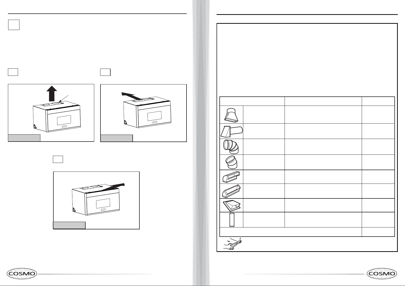
NOTE: Read the next two pages only if you plan to vent your exhaust to the
outside. If you plan to recirculate the air back into the room, proceed to page 20.
EQUIVALENT NUMBER EQUIVALENT
DUCT PIECES LENGTH x USED = LENGTH
Rectangular-to-Round 5 Ft. (1.5 m) x ( ) = Ft. or m
Transition Adaptor*
Wall Cap 40 Ft. (12.2 m) x ( ) = Ft. or m
90° Elbow 10 Ft. (3 m) x ( ) = Ft. or m
45° Elbow 5 Ft. (1.5 m) x ( ) = Ft. or m
90° Elbow 25 Ft. (7.6 m) x ( ) = Ft. or m
45° Elbow 5 Ft. (1.5 m) x ( ) = Ft. or m
Roof Cap 24 Ft. (7.3 m) x ( ) = Ft. or m
Straight Duct 6“ (15.2 cm) 1 Ft. (0.3 m) x ( ) = Ft. or m
Round or 31⁄4“ x 10“
(8.2 x 25.4 cm Rectangular)
Total Ductwork = Ft. or m
Equivalent lengths of duct pieces are based on actual tests
and reflect requirements for good venting performance with
any vent hood.
* IMPORTANT: If a rectangular-to-round transition
adaptor is used, the bottom corners of the damper
will have to be cut to fit, using the tin snips, in order
to allow free movement of the damper
.
NOTE: If you need to install ducts, note that the total
duct length of 31⁄4”x 10”(8.2 x 25.4 cm) rectangular or
”(15.2 cm) diameter round duct
Outside ventilation requires an EXTERNAL EXHAUST
NOTE: It is important that venting be installed using
the most direct route and with as few elbows as possible.
This ensures clear venting of exhaust and helps prevent
blockages. Also, make sure dampers swing freely and
nothing is blocking the ducts.
Exhaust connection:
The exhaust adaptor has been designed to mate with
a standard 31⁄4”x 10”(8.2 x 25.4 cm) rectangular duct.
If a round duct is required, a rectangular-to-round
Maximum duct length:
For satisfactory air movement, the total duct length of
31⁄4”x 10”(8.2 x 25.4 cm) rectangular or
6 ”(15.2 cm) diameter round duct should not
exceed 120 equivalentfeet (36.5 m).
Elbows, transitions, wall and roof caps,
etc., present additional resistance to airflow and are
equivalent to a section of straight duct which is longer
than their actual physical size. When calculating the total
duct length, add the equivalent lengths of all transitions
and adaptors plus the length of all straight duct sections.
The chart below shows you how to calculate total
equivalent ductwork length using the approximate feet
of equivalent length of some typical ducts.
Installation Instructions
INSTALLATION INSTRUCTIONS FOR EXTERNAL EXHAUST DUCTING
DUCT.Read the following carefully.
(12.5”
should not exceed 120 equivalent feet (36.5 m).
diameter/ 6 (12.5”
diameter/ 7 cm)
7 cm)
transition adaptor must be used.
diameter duct is acceptable to use. "
A 5"""'''''" (12.7cm)/ 6" (15.2cm)
"
12 13
EQUIVALENT NUMBER EQUIVALENT
DUCT PIECES LENGTH x USED = LENGTH
Roof Cap 24 Ft. (7.3 m) x (1) = 24 Ft. (7.3 m)
12 Ft. (3.6 m) Straight Duct 12 Ft. (3.6 m) x (1) = 12 Ft. (3.6 m)
(6”/15.2 cm Round)
Rectangular-to-Round 5 Ft. (1.5 m) x (1) = 5 Ft. (1.5 m)
Transition Adaptor*
Equivalent lengths of duct pieces are based on actual tests and
reflect requirements for good venting performance with any vent hood. Total Length = 41 Ft. (12.5 m)
The following chart describes an example of one possible
ductwork installation.
OUTSIDE TOP EXHAUST (EXAMPLE ONLY)
NOTE: For back exhaust, care should be taken to align exhaust with space between studs, or wall should be prepared
at the time it is constructed by leaving enough space between the wall studs to accommodate exhaust.
* IMPORTANT: If a rectangular-to-round transition adaptor is used, the bottom corners of the damper
will have to be cut to fit, using the tin snips, in order to allow free movement of the damper.
The following chart describes an example of one possible
ductwork installation.
Installation Instructions
OUTSIDE BACK EXHAUST (EXAMPLE ONLY)
EQUIVALENT NUMBER EQUIVALENT
DUCT PIECES LENGTH* x USED = LENGTH
Wall Cap 40 Ft. (12.2 m) x (1) = 40 Ft. (12.2 m)
3 Ft. Straight Duct 3 Ft. (0.9 m) x (1) = 3 Ft. (0.9 m)
(31⁄4” x 10”/8.2 x 25.4 cm
Rectangular)
90° Elbow 10 Ft. (3 m) x (2) = 20 Ft. (3 m)
Equivalent lengths of duct pieces are based on actual tests and
reflect requirements for good venting performance with any vent hood. Total Length = 63 Ft. (19.2 m)
EXTERNAL EXHAUST DUCTING
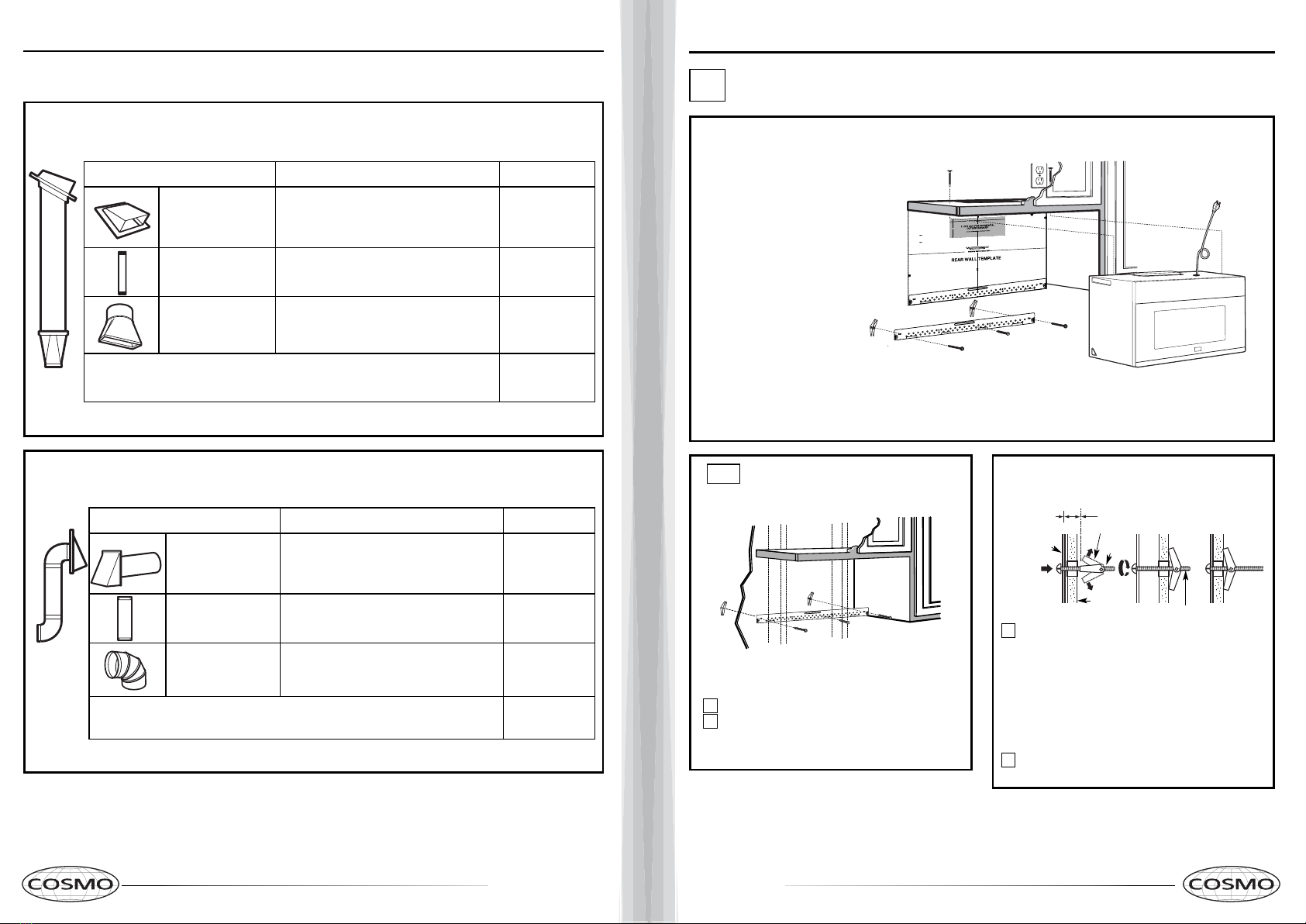
Place the mounting plate against the wall and
insert the toggle wings into the holes in the wall
to mount the plate.
NOTE: Before tightening toggle bolts and wood
screw, make sure the bottom of the mounting plate
touch the bottom of the cabinet when pushed
flush against the wall and that the plate is properly
centered under the cabinet.
CAUTION: Be careful to avoid pinching fingers
between the back of the mounting plate and the wall.
Tighten all bolts. Pull the plate away from the wall
to help tighten the bolts.
3
4
ATTACH THE MOUNTING
PLATE TO THE WALL
A1.
Attach the plate to the wall using toggle bolts.
At least one wood screw must be used to attach
the plate to a wall stud.
Remove the toggle wings from the bolts.
Insert the bolts into the mounting plate
through the holes designated to go into drywall
and reattach the toggle wings to 3⁄4″(19 mm) onto
each bolt.
1
INSTALLATION OVERVIEW
A1. Attach Mounting Plate to Wall
A2. Prepare Top Cabinet
Mount Microwave Oven
A5. Adjust Exhaust Adaptor
A6.
Wall
Mounting
Plate
Spacing for Toggles
More Than Wall
Thickness
Bolt End
Toggle
Bolt
Toggle Wings
To use toggle bolts:
Installation Instructions
2
OUTSIDE TOP EXHAUST (Vertical Duct)
A
IMPORTANT NOTES:
•Make sure the screws for the
blower motor and blower plate
are securely tightened when
they are reinstalled. This will
help to prevent excessive
vibration.
•Make sure the motor wiring has
been properly routed and secured,
and that the wires are not pinched.
A7. Connect Ductwork
A3.
A4. Check Damper Operation
Adapting Microwave Blower for
Outside Top Exhaust
3/8"TO EDGE
NOTE:IT IS VERY IMPORTANT TO
READAND FOLLOWTHE DIRECTIONS
INTHE INSTALLATION INSTRUCTIONS
BEFOREPROCEEDING WITH THIS
REARWALL TEMPLATE.
ThisRearWallTemplate serves to positionthebottom
mountingplate and to locate the horizontal exhaust
outlet.
1.Use a level to checkthat the template is positioned
accurately.
2.Locate and markat least one studon theleft or
right sideof the centerline.
Itis important to use at leastone wood
screwmountedfirmly ina stud to support the weight
ofthe microwave. Mark twoadditional, evenly spaced
locationsforthe supplied toggle bolts.
3.Drill holes in themarked locations.Where there is
a stud, drilla 3/16" holefor wood screws. Forholes
that do not line up with a stud, drill 5/8"holesfor
toggle bolts.
DONOT INSTALLTHE MOUNTINGPLATE
ATTHIS TIME.
4.Removethe template fromthe rearwall.
5.Reviewthe Installation Instruction book for your
installation situation.
Locateand markholes to align with holes in the
mountingplate.
IMPORTANT:
LOCATEATLEAST ONESTUD ON EITHER SIDEOF
THECENTERLINE.
MARKTHE LOCATIONFOR 2 ADDITIONAL, EVENLY
SPACEDTOGGLE BOLTS IN THE MOUNTING PLATE
AREA.
Locateand markholes to align with holes in the
mountingplate.
IMPORTANT:
LOCATEAT LEAST ONE STUD ON EITHER SIDE OF
THECENTERLINE.
MARKTHE LOCATIONFOR 2 ADDITIONAL, EVENLY
SPACEDTOGGLE BOLTS IN THE MOUNTING PLATE
AREA.
Trimthe rear wall template along the dotted line.
Trimthe rear wall template along the dotted line.
12"
4"
Darlevueltaalahojaparaconsultar la
versiónenEspañol.
24"
14 15
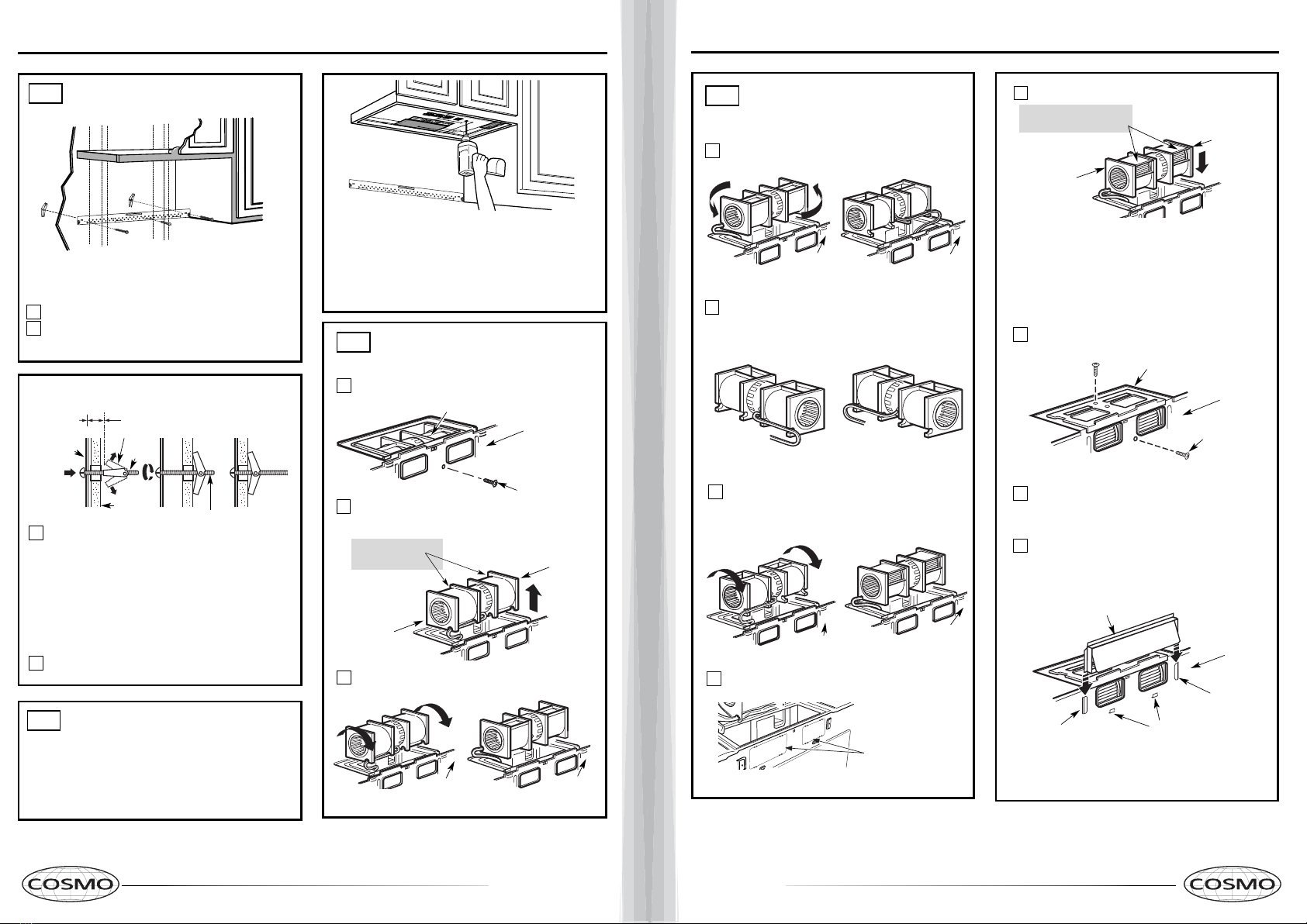
USE TOP CABINET TEMPLATE
FOR PREPARATION OF TOP
CABINET
You need to drill holes for the top support screws, a
hole large enough for the power cord to fit through,
and a cutout large enough for the exhaust adaptor.
A2.
•Read the instructions on the TOP CABINET
TEMPLATE.
•Tape it underneath the top cabinet.
•Drill the holes, following the instructions on the
TOP CABINET TEMPLATE.
CAUTION: Wear safety goggles when drilling holes
in the cabinet bottom.
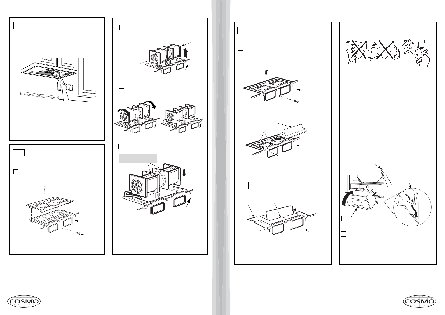
A3.
Remove the screw that holds the blower plate
to the microwave. Remove and save the screw
holding the blower motor to the microwave.
Blower Plate
Blower Motor
Screw
Back of
Microwave
2
End B
End A
Carefully pull out the blower unit. The wires
will extend far enough to allow you to adjust
the blower unit.
1
ADAPTING MICROWAVE
BLOWER FOR OUTSIDE
TOP EXHAUST
Roll the blower unit 90° so that fan blade
microwave.
3
Back of
Microwave
Before Rotation After Rotation
Back of
Microwave
Back of
Microwave
openings are facing out the top of the
Back of
Microwave
AFTER: Fan Blade
Place the blower unit back into the opening.
Openings Facing Top
CAUTION: Do not pull or stretch the blower
unit wiring. Make sure the wires are not
pinched, and that they are properly secured.
4
with the top of the unit facing up.
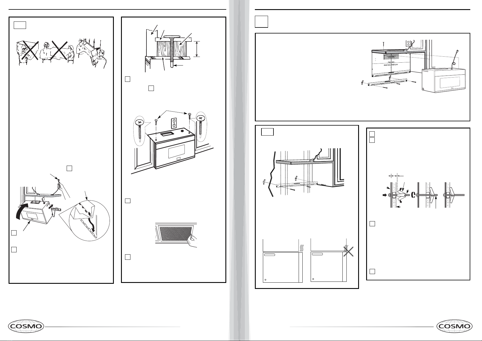
Place the microwave in its upright position,
3
MOUNT THE MICROWAVE
OVEN
FOR EASIER INSTALLATION AND PERSONAL
SAFETY, WE RECOMMEND THAT TWO PEOPLE
INSTALL THIS MICROWAVE OVEN.
NOTE: If your cabinet is metal, use the nylon
grommet around the power cord hole to prevent
cutting of the cord.
NOTE: We recommend using filler blocks if the
cabinet front hangs below the cabinet bottom shelf.
IMPORTANT: If filler blocks are
not used, case damage may occur from
overtightening screws.
Insert a self-aligning screw through top center
cabinet hole. Temporarily secure the oven by
turning the screw at least two full turns after the
threads have engaged. (It will be completely
tightened later.) Be sure to keep power cord
tight. Be careful not to pinch the cord, especially
when mounting flush to bottom of cabinet.
2Rotate front of oven
up against cabinet
bottom.
NOTE: When mounting the
microwave oven, thread
power cord through hole in
bottom of top cabinet. Keep
it tight throughout Steps
1–3. Do not pinch cord or
lift oven by pulling cord. Lift microwave, tilt it
forward, and hook
slots at back bottom
edge onto four lower
tabs of mounting
plate.
1
CHECK FOR PROPER
DAMPER OPERATION
Exhaust Adaptor
Blower Plate
Damper
Back of
Microwave
•Make sure tape securing damper is removed and
damper pivots easily before mounting microwave.
•You will need to make adjustments to assure proper
alignment with your house exhaust duct after the
microwave is installed.
A3.
ADAPTING MICROWAVE
BLOWER FOR OUTSIDE
TOP EXHAUST
Secure blower unit to microwave with the screw
5removed in Step 1. Make sure the screw is tight.
Replace blower plate with the screw removed in
Step 1. Make sure the screw is tight.
Back of
Microwave
6
7
Back of
Microwave
Guide
Adaptor
Locking Tab
damper swings freely.
Attach the exhaust adaptor to the top of the
blower plate by sliding it into the guides of the
blower plate.
Push in securely until it is in the locking tabs.
Take care to assure that the damper hinge is
installed so that the
A4.
A5.
IMPORTANT: Do not grip or use the handle
or heat shield during installation. Do not
remove the cardboard spacers between the
heat shield and door.

16 17
4Attach the microwave oven to the top cabinet.
7
Cabinet Front
Cabinet Bottom Shelf
Tighten the outer two screws to the top of the
microwave oven. (While tightening screws, hold
the microwave oven in place against the wall and
the top cabinet.)
Filler Block
Microwave Oven Top
Equivalent
to Depth
of Cabinet
Recess
Insert 2 self-aligning screws
through outer top cabinet
holes. Turn two full turns on
each screw.
Install grease filters. See the Use &&&&and Care
packed with the microwave.
ADJUST THE EXHAUST
ADAPTOR
Open the top cabinet and adjust the exhaust adaptor
to connect to the house duct.
Back of
Microwave
For Front-to-Back or
Side-to-Side Adjustment,
Slide the Exhaust Adaptor
as Needed
Blower Plate Damper
Self-Aligning Screw
5
MOUNT THE MICROWAVE
OVEN (cont.)
A6.
A5.
CONNECTING DUCTWORK
1
2
Extend the house duct down to connect to
the exhaust adaptor.
A7.
furnance
Seal exhaust duct joints using duct tape
for high temperature applications.
House Duct
6
INSTALLATION OVERVIEW
B1. Prepare Rear Wall
B3. Attach Mounting Plate to Wall
B4. Prepare Top Cabinet
B5. Adjust Blower
B6. Mount the Microwave Oven
IMPORTANT NOTES:
•Make sure the screws for the
blower motor and blower plate
are securely tightened when
they are reinstalled. This will
help to prevent excessive
vibration.
•been properly routed and secured,
and that the wires are not pinched.
Remove and save the screw that holds the blower
plate to the microwave. Lift off the blower plate.
Back of
Microwave
PREPARING THE REAR WALL
FOR OUTSIDE BACK EXHAUST
B1.
You need to cut an opening in the rear wall for
outside exhaust.
•Read the instructions on the REAR
WALL TEMPLATE.
•Tape it to the rear wall.
•Cut the opening, following the instructions of the
REAR WALL TEMPLATE.
B2.
OUTSIDE BACK EXHAUST (Horizontal Duct)
B
Blower Plate
REMOVE BLOWER PLATE
B2. Remove Blower Plate
3/8"TO EDGE
NOTE:IT IS VERY IMPORTANT TO
READAND FOLLOW THE DIRECTIONS
INTHE INSTALLATION INSTRUCTIONS
BEFOREPROCEEDING WITH THIS
REARWALL TEMPLATE.
ThisRearWall Template serves toposition the bottom
mountingplateand tolocate the horizontal exhaust
outlet.
1.Usealevel to check that the template is positioned
accurately.
2.Locateand mark at leastone stud on the leftor
rightside ofthe centerline.
Itisimportant touse at least one wood
screwmountedfirmly in astud to support the weight
ofthemicrowave. Mark two additional, evenly spaced
locationsforthesupplied toggle bolts.
3.Drillholes in the marked locations. Where thereis
astud, drill a 3/16" hole forwood screws. For holes
thatdo not line up with a stud, drill 5/8"holes for
togglebolts.
DONOTINSTALL THE MOUNTING PLATE
ATTHISTIME.
4.Removethetemplate from the rear wall.
5.Reviewthe Installation Instruction bookfor your
installationsituation.
Locateand mark holes to align with holes in the
mountingplate.
IMPORTANT:
LOCATEAT LEAST ONE STUDONEITHER SIDEOF
THECENTERLINE.
MARKTHE LOCATION FOR 2 ADDITIONAL, EVENLY
SPACEDTOGGLE BOLTS IN THE MOUNTING PLATE
AREA.
Locateand mark holes to align with holes in the
mountingplate.
IMPORTANT:
LOCATEAT LEAST ONESTUD ON EITHER SIDE OF
THECENTERLINE.
MARKTHELOCATION FOR 2 ADDITIONAL, EVENLY
SPACEDTOGGLEBOLTS IN THE MOUNTING PLATE
AREA.
Trimthe rear wall template along the dotted line.
Trimtherear wall template along the dotted line.
12"
4"
Darlevuelta a la hoja para consultar la
versiónen Español.
Make sure the motor wiring has
3/8"TO EDGE
NOTE:IT IS VERY IMPORTANT TO
READAND FOLLOWTHE DIRECTIONS
INTHE INSTALLATION INSTRUCTIONS
BEFOREPROCEEDING WITH THIS
REARWALL TEMPLATE.
ThisRearWallTemplate serves to position thebottom
mountingplate and to locate the horizontal exhaust
outlet.
1.Use a level to checkthat the template ispositioned
accurately.
2.Locate and markat least one stud on theleft or
right sideof the centerline.
Itis important to use at leastone wood
screwmountedfirmly ina stud to support the weight
ofthe microwave. Marktwoadditional, evenly spaced
locationsforthe supplied toggle bolts.
3.Drill holesin the marked locations. Where there is
a stud, drilla 3/16" holefor wood screws. Forholes
that do not line up with a stud, drill 5/8"holesfor
toggle bolts.
DONOT INSTALLTHE MOUNTINGPLATE
ATTHIS TIME.
4.Remove the template fromthe rearwall.
5.Reviewthe Installation Instruction book for your
installation situation.
Locateand markholes to align with holes in the
mountingplate.
IMPORTANT:
LOCATEATLEAST ONESTUD ON EITHER SIDEOF
THECENTERLINE.
MARKTHE LOCATIONFOR 2 ADDITIONAL, EVENLY
SPACEDTOGGLE BOLTS IN THE MOUNTING PLATE
AREA.
Locateand markholes to align with holes in the
mountingplate.
IMPORTANT:
LOCATEAT LEAST ONE STUD ON EITHER SIDEOF
THECENTERLINE.
MARKTHE LOCATIONFOR 2 ADDITIONAL, EVENLY
SPACEDTOGGLE BOLTS IN THE MOUNTING PLATE
AREA.
Trimthe rear wall template along the dotted line.
Trimthe rear wall template along the dotted line.
12"
4"
Darlevueltaalahojaparaconsultarla
versiónenEspañol.
24"
24"
18 19
ATTACH THE MOUNTING
PLATE TO THE WALL
B3.
•Read the instructions on the TOP CABINET
TEMPLATE.
•Tape it underneath the top cabinet.
•Drill the holes, following the instructions on the
TOP CABINET TEMPLATE.
CAUTION: Wear safety goggles when drilling holes
in the cabinet bottom.
Wall
Mounting
Plate
Spacing for Toggles More
Than Wall Thickness
Toggle
Bolt
Toggle Wings
To use toggle bolts:
Bolt End
Attach the plate to the wall using toggle bolts.
At least one wood screw must be used to attach
the plate to a wall stud.
Remove the toggle wings from the bolts.
Insert the bolts into the mounting plate through
the holes designated to go into drywall and reattach
the toggle wings to 3⁄4″(19 mm) onto each bolt.
1
2
Place the mounting plate against the wall and
insert the toggle wings into the holes in the wall
to mount the plate.
NOTE: Before tightening toggle bolts and wood
screw, make sure the bottom of the mounting plate
touch the bottom of the cabinet when pushed flush
against the wall and that the plate is properly
centered under the cabinet.
CAUTION: Be careful to avoid pinching fingers
between the back of the mounting plate and the wall.
Tighten all bolts. Pull the plate away from the wall
to help tighten the bolts.
3
4
2
1Remove and save screw that holds blower motor
to microwave.
ADAPTING MICROWAVE
BLOWER FOR OUTSIDE
BACK EXHAUST
B5.
End B
End A
will extend far enough to allow you to adjust
the blower unit.
Back of
Microwave
Blower Motor
Blower Motor
Screw
Forward
Openings Facing
Carefully pull out the blower unit. The wires
Before: Fan Blade
USE TOP CABINET TEMPLATE
FOR PREPARATION OF TOP
CABINET
B4.
You need to drill holes for the top support screws and
a hole large enough for the power cord to fit through. Back of
Microwave
Roll the blower unit 90°
Back of
Microwave
3Before Rotation After Rotation
Attach the exhaust adaptor to the rear of the
oven by sliding it into the guides at the top
center of the back of the oven.
AFTER: Fan Blade
Openings Facing Back
Place the blower unit back into the opening.
Replace the blower plate in the same position
as before with the screw. Make sure the screw
is tight.
Roll the blower unit 90° so that fan blade
openings are facing out the back of the
microwave.
ADAPTING MICROWAVE
BLOWER FOR OUTSIDE
BACK EXHAUST (cont.)
B5.
Rotate blower unit counterclockwise 180°.
Before Rotation After Rotation
Gently remove the wires from the grooves.
Reroute the wires through grooves on other side
of the blower unit.
Before Rerouting After Rerouting
Wires Routed Through Right Side Wires Routed Through Left Side
Back of
Microwave Back of
Microwave
Blower Plate
Blower Motor
Screw
Secure the blower unit to the microwave with
the original screw.
Before Rolling After Rolling
Back of
Microwave
End A
End B
Back of
Microwave
Back of
Microwave
CAUTION: Do not pull or stretch the blower
unit wiring. Make sure the wires are not
pinched, and that they are properly secured.
NOTE: The blower unit exhaust
openings should match exhaust
openings on rear of microwave oven.
Push in securely until it is in the lower locking
tabs. Take care to assure that the damper hinge
is installed so that it is at the top and that the
damper swings freely.
Guide
Guide
Adaptor
Locking Tabs
Back of
Microwave
4
5
6
11
Back of mircrowave
Knockout Plates:
Snip all 4 webs on
each knockout panel
and remove the metal
knockouts for rear airflow.
Please take care to
remove any sharp edges
created from removing
the knockout plates.
7
8
9
10
with snips. (For some models)
Remove the knockout plates in the back of the unit
20 21
Attach the microwave oven to the top cabinet.
3
MOUNT THE MICROWAVE
OVEN
B6.
FOR EASIER INSTALLATION AND PERSONAL
SAFETY, WE RECOMMEND THAT TWO PEOPLE
INSTALL THIS MICROWAVE OVEN.
NOTE: If your cabinet is metal, use the nylon
grommet around the power cord hole to prevent
cutting of the cord.
NOTE: We recommend using filler blocks if the
cabinet front hangs below the cabinet bottom shelf.
IMPORTANT: If filler blocks are not
used, case damage may occur from
overtightening screws.
Insert a self-aligning screw through top center
cabinet hole. Temporarily secure the oven by
turning the screw at least two full turns after the
threads have engaged. (It will be completely
tightened later.) Be sure to keep power cord
tight. Be careful not to pinch the cord, especially
when mounting flush to bottom of cabinet.
8
7
5
Cabinet Front
Cabinet Bottom Shelf
Tighten the outer two screws to the top of the
microwave oven. (While tightening screws, hold
the microwave oven in place against the wall and
the top cabinet.)
Filler Block
Microwave Oven Top
Equivalent
to Depth
of Cabinet
Recess
Insert 2 self-aligning screws
through outer top cabinet
holes. Turn two full turns on
each screw.
packed with the microwave.
Self-Aligning Screw
4
2Rotate front of oven
up against cabinet
bottom.
NOTE: When mounting the
microwave oven, thread
power cord through hole in
bottom of top cabinet. Keep
it tight throughout Steps
1–3. Do not pinch cord or
lift oven by pulling cord. Lift microwave, tilt it
forward, and hook
slots at back bottom
edge onto four lower
tabs of mounting
plate.
1
Install grease filters. See the Use &&&&and Care
IMPORTANT: Do not grip or use the handle
or heat shield during installation. Do not
remove the cardboard spacers between the
heat shield and door.
INSTALLATION OVERVIEW
C1. Attach Mounting Plate to Wall
C2. Prepare Top Cabinet
C4.
C5. Mount the Microwave Oven
IMPORTANT NOTES:
•Make sure the screws for the blower motor and blower
plate are securely tightened when they are reinstalled.
This will help to prevent excessive vibration.
•Make sure the motor wiring has been properly routed
and secured, and that the wires are not pinched.
Place the mounting plate against the wall and
insert the toggle wings into the holes in the wall
to mount the plate.
NOTE: Before tightening toggle bolts and wood
screw, make sure the bott m of the mounting plate
touch the bottom of the cabinet when pushed flush
against the wall and that the plate is properly
centered under the cabinet.
CAUTION: Be careful to avoid pinching fingers
between the back of the mounting plate and the wall.
Tighten all bolts. Pull the plate away from the wall
to help tighten the bolts.
4
3
ATTACH THE MOUNTING
PLATE TO THE WALL
C1.
Attach the plate to the wall using toggle bolts.
At least one wood screw must be used to attach
the plate to a wall stud.
Remove the toggle wings from the bolts.
Insert the bolts into the mounting plate through
the holes designated to go into drywall and
reattach the toggle wings to 3⁄4″(19 mm) onto
each bolt.
1
Wall
Mounting
Plate
Spacing for Toggles
More Than Wall
Thickness
Bolt End
Toggle
Bolt
Toggle Wings
To use toggle bolts:
2
RECIRCULATING (Non-Vented Ductless)
C
Install or change Charcoal Filter
C3. Check Blower Plate
NOTE:
Cabinet
Cabinet
If the cabinet depth including the cabinet doors
is more than 13""'' then the unit must be spaced
out from wall using adequate materials supporting
150 Ibs to allow proper top vent air exhaust/intake.
o
3/8"TOEDGE
NOTE:ITIS VERY IMPORTANT TO
READANDFOLLOWTHE DIRECTIONS
INTHEINSTALLATION INSTRUCTIONS
BEFOREPROCEEDINGWITH THIS
REARWALLTEMPLATE.
ThisRearWallTemplateserves to position thebottom
mountingplateand to locate the horizontal exhaust
outlet.
1.Usea level to checkthat the template ispositioned
accurately.
2.Locateand markat least one studon theleft or
rightsideofthe centerline.
Itisimportant to useat leastone wood
screwmountedfirmlyina stud to support the weight
ofthemicrowave. Marktwoadditional, evenly spaced
locationsforthesupplied toggle bolts.
3.Drillholesin themarked locations.Where there is
astud,drilla 3/16" holeforwood screws. For holes
thatdonot line up with a stud, drill 5/8"holes for
togglebolts.
DONOTINSTALLTHE MOUNTING PLATE
ATTHISTIME.
4.Removethetemplate fromthe rearwall.
5.Reviewthe Installation Instruction book for your
installationsituation.
Locateandmarkholes to align with holes in the
mountingplate.
IMPORTANT:
LOCATEATLEASTONESTUD ON EITHER SIDE OF
THECENTERLINE.
MARKTHELOCATION FOR 2 ADDITIONAL, EVENLY
SPACEDTOGGLEBOLTS IN THE MOUNTING PLATE
AREA.
Locateandmarkholes to align with holes in the
mountingplate.
IMPORTANT:
LOCATEATLEAST ONE STUD ON EITHER SIDEOF
THECENTERLINE.
MARKTHELOCATIONFOR 2 ADDITIONAL, EVENLY
SPACEDTOGGLEBOLTS IN THE MOUNTING PLATE
AREA.
Trimtherear wall template along the dotted line.
Trimtherear wall template along the dotted line.
12"
4"
Darlevueltaalahojaparaconsultar la
versiónenEspañol.
22 23
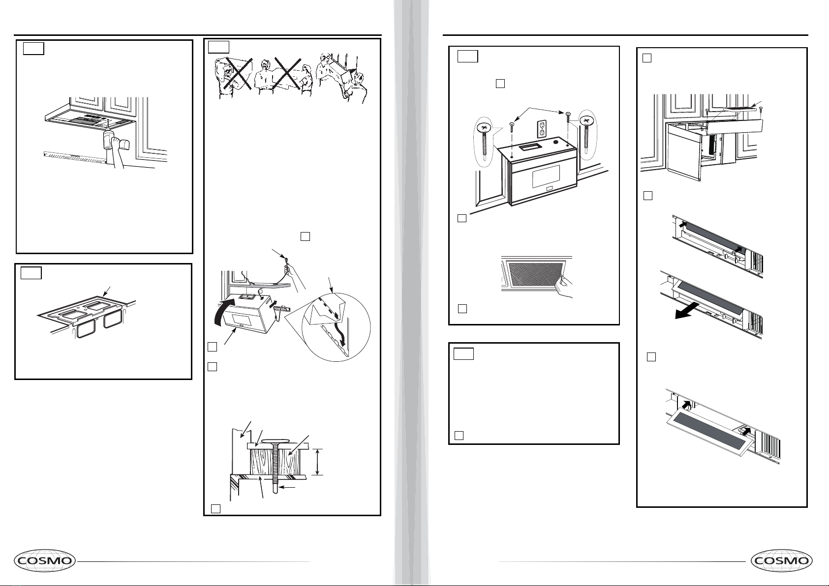
Attach the microwave oven to the top cabinet.
Cabinet Front
Cabinet Bottom Shelf
Filler Block
Microwave Oven Top
Equivalent to Depth
of Cabinet Recess
3
MOUNT THE MICROWAVE OVEN
FOR EASIER INSTALLATION AND PERSONAL
SAFETY, WE RECOMMEND THAT TWO PEOPLE
INSTALL THIS MICROWAVE OVEN.
NOTE: If your cabinet is metal, use the nylon
grommet around the power cord hole to prevent
cutting of the cord.
NOTE: We recommend using filler blocks if the
cabinet front hangs below the cabinet bottom shelf.
IMPORTANT: If filler blocks are not used,
case damage may occur from overtightening
screws.
Insert a self-aligning screw through top center
cabinet hole. Temporarily secure the oven by
turning the screw at least two full turns after the
threads have engaged. (It will be completely
tightened later.) Be sure to keep power cord
tight. Be careful not to pinch the cord, especially
when mounting flush to bottom of cabinet.
Self-Aligning Screw
4
2Rotate front of oven
up against cabinet
bottom.
NOTE: When mounting the
microwave oven, thread
power cord through hole in
bottom of top cabinet. Keep
it tight throughout Steps
1–3. Do not pinch cord or
lift oven by pulling cord. Lift microwave, tilt
it forward, and hook
slots at back bottom
edge onto four lower
tabs of mounting
plate.
1
C3.
C4.
CHECK BLOWER PLATE
Blower Plate
•Place the microwave in its upright position, with the
top of the unit facing up.
•Check to see that the blower plate is correctly
installed on the unit.
USE TOP CABINET TEMPLATE
FOR PREPARATION OF TOP
CABINET
C2.
•Read the instructions on the TOP CABINET
TEMPLATE.
•Tape it underneath the top cabinet.
•Drill the holes, following the instructions on the
TOP CABINET TEMPLATE.
CAUTION: Wear safety goggles when drilling holes
in the cabinet bottom.
You need to drill holes for the top support screws and
a hole large enough for the power cord to fit through.
Adjust top template accordingly if the microwave
is being spaced out from the wall due to cabinet depth
(including cabinet doors) of more th n 13"""''.
NOTE:
a
IMPORTANT: Do not grip or use the handle
or heat shield during installation. Do not
remove the cardboard spacers between the
heat shield and door.
5
MOUNT THE MICROWAVE
OVEN (cont.)
8
7Tighten the outer two screws to the top of the
microwave oven. (While tightening screws, hold
the microwave oven in place against the wall and
the top cabinet.)
Insert 2 self-aligning screws
through outer top cabinet
holes. Turn two full turns on
each screw.
packed with the microwave.
C4.
Install grease filters. See the Use &&&&and Care
C5. INSTALLING OR CHANGE
THE CHARCOAL FILTER
(Some Models)
Unplug microwave oven or disconnect power.
1
NOTE: The charcoal filter is factory installed in some
models. Refer to the Use and Care to see if yours is
factory installed and for replacement information.
For models without the recirculation filter access
3
Open the microwave door and remove the two
vent mounting screws ;located on top of the
microwave using a #1 Phillips screwdriver.
2
4
Remove the charcoal filter by pushing the
top of the filter inwards,then pull it forward
out from the unit.
Slide the top of the new charcoal filter into the
top of the filter cavity.
door,follow these steps to replace or install a charcoal
filter.
Charcoal
Filter

24 25
Close the microwave door. Plug in microwave
oven or reconnect power.
Reinstall the vent by sliding the bottom of the
vent into place. Push the vent top into position
and slide right into place. Replace the two vent
mounting screws located on top of the microwave
using a #1 Phillips screwdriver.
Press the bottom of charcoal filter to place it
into the correct position.
5
6
7
Remove all packing material from the
microwave oven.
2.
Make sure the microwave oven has been
installed according to instructions.
1.
BEFORE YOU USE YOUR MICROWAVE
Ensure proper
ground exists
before use
INSTALLATION
INSTRUCTIONS
3. ring and glass tray in cavity.
Install turntable
4.
KEEP INSTALLATION INSTRUCTIONS
FOR THE LOCAL INSPECTOR’S
USE.
7.
6.
INSTALLATION
INSTRUCTIONS
MANUAL
USE
|++&=
CARE
+
&
PRODUCT
CARD
Read the Manual.
&
REGISTRATION
USE CARE
Replace house fuse or turn breaker back on.
5.
FILL OUT PRODUCT REGISTRATION CARD
.
8
AN SEND IN.
Plug power cord into a seperate and dedicated
15- to 20-amp electrical outlet.

26 27
3/8" TO ED
GE
NOTE: IT IS VER
Y IMPORTA
NT
TO
READ AND FOLLOW T
HE DIRECT
ION
S
IN THE INST
ALL
ATION
INSTRU
CTIONS
BEFORE PROC
EEDING
WITH THIS
REAR WAL
L TEMPLA
TE.
This Rear Wall Template serves to po
sition the bottom
m
ounting plate and to locate the horizontal exhaust
outlet.
1. Use a level to check that the template is positioned
accurately.
2. Locate and mark at least one
stud on the left or
right side of the centerline.
It is important to use at least one w
ood
screw mounted
firmly in a stud to support the weight
of the
microwave. Mark tw
o additional, evenly space
d
locations for the supplied toggle bolts.
3. Drill holes in the ma
rked locations. Where
there is
a stud, drill a 3/16" hole for woo
d screws. For ho
les
that do not line up with a stud, dri ll 5/8" holes for
toggle bolts.
D
O NOT INSTALL TH
E M
O
U
NT
IN
G
PLAT
E
AT
THIS TIME.
4. Rem
ove the templ
ate from
the rear wall.
5. Review the Installation Instruction book for your
installation situation.
Locate and m
ark holes to align with holes in the
mo
unting plate.
IM
PORTANT
:
LO
CATE AT
LEAS
T ONE STUD
ON
EITHER SIDE OF
THE
CENTERLI
NE.
MA
RK THE
LOCAT
ION
FOR 2 ADDITIONA
L, EVE
NLY
SPACE
D TOGGLE B
OLT
S IN THE MOUNT
ING PLA
TE
AR
EA.
Locate and ma
rk holes to align with holes in the
mou
nting plate.
IM
PORTANT
:
LOC
AT
E AT LEAST ONE STU
D O
N EITHER SIDE OF
THE CENT
ERL
INE.
MA
RK THE LOC
AT
ION FOR
2 AD
DITIONAL, EVENLY
SPA
CE
D TOGGLE BOLTS IN THE
MO
UNTI
NG PLAT
E
AREA.
Trim the rear wall template along the dotted line.
Trim the rear wall template
along
the dotted line.
12"
4"
D
arle vuelta a la hoja pa
ra consultar la
versió
n en Espaol.
3/8" TO
EDG
E
NO
TE: IT IS VERY IMPO
RTANT TO
READ
A
N
D FOLLOW
THE D
IRECTIO
NS
IN TH
E INSTALLATION INS
TRUCTIO
NS
BEFORE PROCEEDING
W
ITH THIS
REAR W
ALL TEMPL
ATE.
This Rear Wall Temp
late serves to position the bottom
moun
ting plate and to locate the horizontal exhaust
outlet.
1. Use a level to check that the template is position
ed
accurately.
2. Locate and m
ark at least one stud on the
left or
right side of the centerline.
It is important to use at least one wood
screw m
ou
nted firmly in a stud to supp
ort the weight
of the mi
crowave. Mark tw
o additional, evenly spaced
locations for the supplied toggle bolts.
3. D
rill holes in the ma
rked locations. Where there is
a stud, drill a 3/16" hole for woo
d screws. For holes
that do not line up w
ith a stud, drill 5/8" holes for
toggle bolts.
D
O
NOT INSTA
LL TH
E M
O
U
NT
ING
PLATE
A
T THIS TIME.
4. Remove the templat
e from the
rear wall.
5. Review
the Installation Instruction
book for your
installation situation.
Locate and mark holes to align with holes in the
mountin
g plate.
IM
PORTANT:
LO
CAT
E AT LEAST ONE S
TUD
ON
EITHER SIDE OF
THE CEN
TERLIN
E.
MARK THE LO
CA
TIO
N FOR 2 ADDITION
AL
, EVENLY
SPACED
TOGGLE BO
LTS IN THE MOUNT
ING
PLATE
AREA.
Locate and mark holes to align with holes in the
mountin
g plate.
IM
POR
TANT:
LOCAT
E AT LEAST
ONE STUD
ON
EITHER SIDE OF
THE CEN
TERLINE.
MA
RK TH
E LOCATIO
N FOR
2 ADDITION
AL, EVENLY
SPA
CE
D TOGGLE
BOLTS IN THE MOUNTING
PLATE
AREA.
Trim the rear wall template along the dotted line
.
Trim the rear wall template alon
g the dotted line
.
12"
4"
Darle vuelta a la hoja para consultar la
versión en Espaol.
10-23/64
10-23/64
PN:16170000A53735
WARRANTY AND SERVICE
For full warranty details on this product please visit:
http://www.cosmoappliances.com/warranty
TO RECEIVE WARRANTY SERVICE, YOUR
PRODUCT MUST BE REGISTERED. TO REGISTER, VISIT:
WWW.COSMOAPPLIANCES.COM/WARRANTY
Correct Disposal of this product:
This marking indicates that this appliance should not
be disposed with other household wastes. To prevent
possible harm to the environment or human health
from uncontrolled waste disposal, recycle it responsibly to
promote the sustainable reuse of material resources.
IMPORTANT
Do Not Return This Product To The Store If
you have a problem with this product, please contact
Cosmo Customer Support at
+1(888)784-3108
DATED PROOF OF PURCHASE, MODEL #, AND SERIAL #
REQUIRED FOR WARRANTY SERVICE
IMPORTANT
Ne pas Réexpédier ce Produit au Magasin
Pour tout problème concernant ce produit, veuillez contacter
le service des consommateurs Cosmo Customer Support au
+1(888) 784-3108
UNE PREUVE D’ACHAT DATEE EST REQUISE POUR BENEFICIER DE
LA GARANTIE.
IMPORTANTE
No regrese este producto a la tienda
Si tiene algún problema con este producto, por favor contacte el
AYUDA AL CLIENTE COSMO al
+1(888)784-3108
(Válido solo en E.U.A).
NECESITA UNA PRUEBA DE DE COMPRA FECHADA, NÚMERO DE
MODELO Y DE SERIE PARA EL SERVICIO DE LA GARANTÍA
SCAN TO REGISTER
Electronic version of this manual is available at:
www.cosmoappliances.com
Cosmo is constantly making efforts to improve the quality and
performance of our products, so we may make changes to our
appliances without updating this manual.
Other manuals for COS-2413ORM1SS
2
Table of contents
Other Cosmo Microwave Oven manuals

Cosmo
Cosmo COS-3012ORLP1SS User manual

Cosmo
Cosmo COS-3016ORM1SS User manual

Cosmo
Cosmo COS-3019ORM2SS User manual

Cosmo
Cosmo COS-12MWDSS User manual

Cosmo
Cosmo COS-3016ORM1SS User manual

Cosmo
Cosmo COS-2413ORM1SS User manual

Cosmo
Cosmo COS-BIM22SSB User manual

Cosmo
Cosmo COS-2413ORM1SS User manual

Cosmo
Cosmo COS-MWD3012GSS User manual

Cosmo
Cosmo COS-07CTMSSB User manual


 Operation manual")


