Cosmo COS-3016ORM1SS User manual

IMPORTANT SAFETY INSTRUCTIONS
Carefully read the following Important information regarding installation
safety and maintenance. Keep these instruction for future reference.
INSTALLATION GUIDE
COS-3016ORM1SS
OVER THE RANGE
MICROWAVE
I N S P I R I N G T H E W O R L D ’ S K I T C H E N
COS-3016ORM1SS INSTALL GUIDE
2 3
Contents
Introduction . . . . . . . . . . . . . . . . . . . . . . . . . . . . . . . . . . . . . . . . . . . . . . . . . . . . . . . . . . . 4
BEFORE YOU BEGIN . . . . . . . . . . . . . . . . . . . . . . . . . . . . . . . . . . . . . . . . . . . . . . . . . . . . 4
IMPORTANT SAFETY INSTRUCTIONS . . . . . . . . . . . . . . . . . . . . . . . . . . . . . . . . . . . . 4
ELECTRICAL REQUIREMENTS . . . . . . . . . . . . . . . . . . . . . . . . . . . . . . . . . . . . . . . . . . . . . . . . . . . . . . . . . . .4
Package contents . . . . . . . . . . . . . . . . . . . . . . . . . . . . . . . . . . . . . . . . . . . . . . . . . . . . . . . 5
Parts . . . . . . . . . . . . . . . . . . . . . . . . . . . . . . . . . . . . . . . . . . . . . . . . . . . . . . . . . . . . . . . . . . . . . . . . . . . . . . . . . 5
Hardware . . . . . . . . . . . . . . . . . . . . . . . . . . . . . . . . . . . . . . . . . . . . . . . . . . . . . . . . . . . . . . . . . . . . . . . . . . . . . 5
Before you install . . . . . . . . . . . . . . . . . . . . . . . . . . . . . . . . . . . . . . . . . . . . . . . . . . . . . . .6
Tools and materials needed . . . . . . . . . . . . . . . . . . . . . . . . . . . . . . . . . . . . . . . . . . . . . . . . . . . . . . . . . . . .6
Mounting requirements . . . . . . . . . . . . . . . . . . . . . . . . . . . . . . . . . . . . . . . . . . . . . . . . . . . . . . . . . . . . . . . 7
Exhaust requirements . . . . . . . . . . . . . . . . . . . . . . . . . . . . . . . . . . . . . . . . . . . . . . . . . . . . . . . . . . . . . . . . . 8
Removing your microwave . . . . . . . . . . . . . . . . . . . . . . . . . . . . . . . . . . . . . . . . . . . . . .10
Installing your microwave . . . . . . . . . . . . . . . . . . . . . . . . . . . . . . . . . . . . . . . . . . . . . . .11
Step 1: Find the wall studs . . . . . . . . . . . . . . . . . . . . . . . . . . . . . . . . . . . . . . . . . . . . . . . . . . . . . . . . . . . . .11
Step 2: Align the rear wall template . . . . . . . . . . . . . . . . . . . . . . . . . . . . . . . . . . . . . . . . . . . . . . . . . . . .12
Step 3: Select a ventilation type . . . . . . . . . . . . . . . . . . . . . . . . . . . . . . . . . . . . . . . . . . . . . . . . . . . . . . . .14
Step 4: Option A - Attach the mounting plate to the wall . . . . . . . . . . . . . . . . . . . . . . . . . . . . . . . .15
Step 5: Option A - Preparing the top cabinet . . . . . . . . . . . . . . . . . . . . . . . . . . . . . . . . . . . . . . . . . . . .17
Step 6: Option A - Adapt the microwave blower for outside top exhaust . . . . . . . . . . . . . . . . . 19
Step 7: Option A - Mount the microwave . . . . . . . . . . . . . . . . . . . . . . . . . . . . . . . . . . . . . . . . . . . . . . . 21
Step 8: Option A - Connecting duct work . . . . . . . . . . . . . . . . . . . . . . . . . . . . . . . . . . . . . . . . . . . . . . .23
Step 4: Option B - Cutting a vent opening . . . . . . . . . . . . . . . . . . . . . . . . . . . . . . . . . . . . . . . . . . . . . . 24
Step 5: Option B - Attach the mounting plate to the wall . . . . . . . . . . . . . . . . . . . . . . . . . . . . . . . . 25
Step 6: Option B - Preparing the top cabinet . . . . . . . . . . . . . . . . . . . . . . . . . . . . . . . . . . . . . . . . . . . .27
Step 7: Option B - Adapt the microwave blower for outside back exhaust . . . . . . . . . . . . . . . .29
Step 8: Option B - Mount the microwave . . . . . . . . . . . . . . . . . . . . . . . . . . . . . . . . . . . . . . . . . . . . . . . 32
Step 4: Option C - Attach the mounting plate to the wall . . . . . . . . . . . . . . . . . . . . . . . . . . . . . . . . 34
Step 5: Option C - Preparing the top cabinet . . . . . . . . . . . . . . . . . . . . . . . . . . . . . . . . . . . . . . . . . . . . 36
Step 6: Option C - Mount the microwave . . . . . . . . . . . . . . . . . . . . . . . . . . . . . . . . . . . . . . . . . . . . . . . 38
Before using your microwave . . . . . . . . . . . . . . . . . . . . . . . . . . . . . . . . . . . . . . . . . . . 40
Obtaining replacement parts . . . . . . . . . . . . . . . . . . . . . . . . . . . . . . . . . . . . . . . . . . . . 40
Specifications . . . . . . . . . . . . . . . . . . . . . . . . . . . . . . . . . . . . . . . . . . . . . . . . . . . . . . . . . . 40
Template dimensions . . . . . . . . . . . . . . . . . . . . . . . . . . . . . . . . . . . . . . . . . . . . . . . . . . . 41
Rear wall template dimensions . . . . . . . . . . . . . . . . . . . . . . . . . . . . . . . . . . . . . . . . . . . . . . . . . . . . . . . . 41
Top cabinet template dimensions . . . . . . . . . . . . . . . . . . . . . . . . . . . . . . . . . . . . . . . . . . . . . . . . . . . . . . 42
Legal notices . . . . . . . . . . . . . . . . . . . . . . . . . . . . . . . . . . . . . . . . . . . . . . . . . . . . . . . . . . . 43
TWO-YEAR LIMITED WARRANTY . . . . . . . . . . . . . . . . . . . . . . . . . . . . . . . . . . . . .. . . . 43
THANK YOU FOR YOUR PURCHASE
Thank you for your purchase. We know that you have many brands and
products to choose from and we are honored to know that you have decided
to take one of our products into your home and hope that you enjoy it.
COSMO appliances are designed according to the strictest safety and performance
standard for the North American market. We follow the most advanced
manufacturing philosophy. Each appliance leaves the factory after thorough
quality inspection and testing. Our distributors and our service partners are
ready to answer any questions you may have regarding how to install, use and
care for your products. We hope that this manual will help you learn to use the
product in the safest and most effective manner .
If you have any questions or concerns, please contact the dealer from whom you
purchased it, or contact our Customer Support at:
1-888-784-3108.
Specifications
Model
Rated voltage 120V / 60 Hz
Rated input power 1550W
Rated output power 1000W
Microwave capacity 1.6 cu. ft.
Turntable diameter 13.5 in. (34.5 cm)
External dimensions (WxDxH) 29.9 x 15 x 16.4 in. (75.9 × 38.2× 41. 7 cm)
Internal dimensions (WxDxH) 20.24 x 14.41 x 9.25 (51.4 × 36.6 × 23. 5 cm)
Certifications UL approved
Power cord length 3.3 ft. (1 m)
Net weight 56 lbs. (25.4 kg)
COS-3016ORM1SS

4 5
Introduction
This installation guide will show you how to install your new over-the-range microwave.
BEFORE YOU BEGIN
Read these instructions completely and carefully.
• IMPORTANT – Save these instructions for local inspector’s use.
• IMPORTANT – Observe all governing codes and ordinances.
• Note to Installer – Be sure to leave these instructions with the consumer.
• Note to Consumer – Keep these instructions for future reference.
• Skill level – Installation of this appliance requires basic mechanical and electrical skills.
• Proper installation is the responsibility of the installer.
• Product failure due to improper installation is not covered under the Warranty.
IMPORTANT SAFETY INSTRUCTIONS
IMPORTANT–PLEASE READ CAREFULLY. FOR PERSONAL SAFETY, THIS APPLIANCE MUST BE PROPERLY GROUNDED
TO AVOID SEVERE OR FATAL SHOCK.
This product requires a three-prong, properly grounded outlet for safe
operation. If not properly grounded, or if the outlet box does not meet
electrical requirements noted (under ELECTRICAL REQUIREMENTS), a qualified
electrician should be employed to correct any deficiencies.
The power cord of this appliance is equipped with a three-prong (grounding)
plug which mates with a standard three-prong (grounding) wall receptacle to
minimize the possibility of electric shock hazard from this appliance.
You should have the wall receptacle and circuit checked by a qualified electrician to make sure that the receptacle is
properly grounded.
Where a standard two-prong wall receptacle is encountered, it is very important to have it replaced with a properly
grounded three-prong wall receptacle installed by a qualified electrician.
DO NOT, UNDER ANY CIRCUMSTANCES, CUT, DEFORM, OR REMOVE ANY OF THE PRONGS FROM THE POWER CORD.
DO NOT USE WITH AN EXTENSION CORD.
Caution
For personal safety, remove the house fuse or open the circuit breaker before beginning
installation to avoid severe or fatal shock injury.
For personal safety, the mounting surface must be capable of supporting the cabinet load,
in addition to the added weight of this 56-lb. (25.4 kg) product, plus additional oven loads
of up to 50 pounds (22 kilograms) for a total weight of 106 lbs. (46.4 kg).
For personal safety, this product cannot be installed in cabinet arrangements such as an
island or a peninsula. It must be mounted to BOTH a top cabinet AND a wall.
ELECTRICAL REQUIREMENTS
The product rating of your microwave is 120 volts AC, 60 Hertz, 15 amps, and 1.6 kilowatts. This product must be
connected to a supply circuit of the proper voltage and frequency. Wire size must conform to the requirements of
the National Electrical Code or the prevailing local code for this kilowatt rating. The power supply cord and plug
should be brought to a separate 20 ampere branch circuit single grounded outlet. The outlet box should be located
in the cabinet above the microwave oven. The outlet box and supply circuit should be installed by a qualified
electrician and conform to the National Electrical Code or the prevailing local code.
Note
For easier installation and personal safety, it is recommended that two people
install this product.
Ensure proper
ground before
use
Congratulations on your purchase of a high-quality product. Your represents the state of the art in microwave
design and is designed for reliable and trouble-free performance.
PART QUANTITY
Wood Screws 2
(
1
⁄
4
“ x 2“)
Toggle Bolts (and
wing nuts) (
3
⁄
16
“ x 3“)
Self-Aligning Machine 3
Screws (
1
⁄
4
“-28 x 3
1
⁄
4
“)
Nylon Grommet
(for metal cabinets) 1
•
If the unit is damaged in shipment, return the
unit to the store in which it was bought for repair
or replacement.
•
If the unit is damaged by the customer, repair or
replacement is the responsibility of the customer.
•
If the unit is damaged by the installer (if other
than the customer), repair or replacement must
be made by arrangement between customer
and installer.
DAMAGE—SHIPMENT/
INSTALLATION
PARTS INCLUDED
You will find the installation hardware contained in
a packet with the unit. Check to make sure you have
all these parts.
NOTE: Some extra parts are included.
HARDWARE PACKET
PART
QUANTITY
Template 1
Template
Installation
1
Instructions
Separately 2
Packed
Filters
PARTS INCLUDED
(CONT.)
INSTALLATION
INSTRUCTIONS
ADDITIONAL PARTS
1
adaptor
Exhaust
Glass
1
Tray
1
Ring
T ru ntable
CabinetTop
Rear Wall
2
1
Use & Care
1
USE & CARE
MANUAL
Manual
Grease

66 in. (167.6 cm) or more
from the floor to the top of
the microwave
16-1/2 in.
(41.9 cm)
30in.(76.2cm)
30 in.
(76.2 cm)
2 in. (5.1 cm)
67
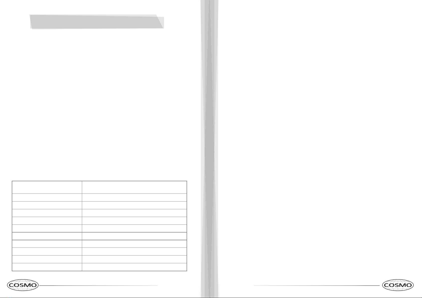
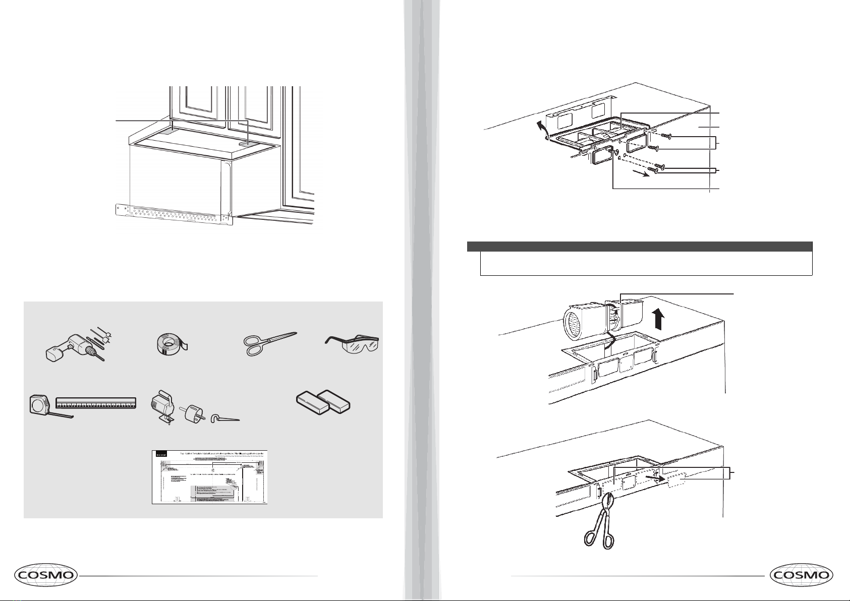
TOOLS YOU WILL NEED
# 1 Phillips screwdriver Pencil Ruler or tape measure and
straight edge Carpenter square
(optional)
Tin snips (for cutting
damper, if required) Electric drill with 3⁄16“, 1⁄2“and 5⁄8“
drill bits
Hammer (optional)
Stud finder or
Filler blocks or scrap
wood pieces, if needed
for top cabinet spacing
(used on recessed bottom
cabinet installations only)
Gloves
Saw (saber, hole or keyhole)
Level Duct and masking tape
Scissors
(to cut template, if necessary)
Safety goggles
Mounting requirements
• The space between the cabinets must be 30 in. (76.2 cm) wide. If the space between
the cabinets is more than 30 in. (76.2 cm), you’ll need filler material to fill the gap
between the microwave and cabinets.
• This microwave is for installation over ranges up to 36 in. (91.4 cm) wide.
•If installing the microwave beneath smooth, flat cabinets, make sure that you leave
enough space for the power cord clearance.
• If you are going to vent your exhaust to the outside, see “Exhaust requirements” on
page 8 for exhaust duct preparation.

89
Exhaust requirements
Use this section if you plan to vent your microwave outside (top or back exhaust). If you plan
to recirculate the air back into the room, skip to “Removing your microwave” on page 9.
When installing exhaust vents:
• Use the most direct route with as few elbows/transitions as possible. This helps prevent
blockages and ensures
that the exhaust is being vented correctly.
• Your microwave is designed to mate with a standard 3-1/4” × 10” rectangular duct. If a
round duct is required, a
rectangular-to-round transition adapter must be used. Do not use a duct with a diameter
less than 6”.
• Elbows, transitions, and wall/roof caps add resistance to airflow. Each of these pieces are equivalent to a section
of straight duct that is longer than their actual physical size. When calculating your duct length, add the
equivalent lengths of all the pieces together. For proper airflow, the equivalent airflow should not exceed 120 ft.
For example:
Note
If a rectangular-to-round transition adapter is used, you must cut the bottom
corners of the damper wih tin snips to let the damper have free movement.
Note
Equivalent lengths of duct pieces are based on actual tests and reflect
requirements for good venting performance with any vent hood.
Use the “Equivalent duct length table” on page 9 to calculate
the equivalent duct-work length for your setup.
To calculate your equivalent duct length:
1Write the number of sections used for each of the duct pieces.
2Multiply the number used by the equivalent length for each duct piece.
3Add the total equivalent lengths together. This number must be less than 120 ft.
Duct Pieces Equivalent
Length × Number Used =
Total
Equivalent
Length
5 ft. × ( ) = ft.
40 ft. × ( ) = ft.
10 ft. × ( ) = ft.
5 ft. × ( ) = ft.
25 ft. × ( ) = ft.
5 ft. × ( ) = ft.
24 ft. × ( ) = ft.
1 ft. × ( ) = ft.
Total ductwork =
ft.
(For proper airflow, this
number should not
exceed 120 ft.)
Rectangular-to-
round transition
adapter
Wall cap
90° elbow
45° elbow
90° elbow
45° elbow
Roof cap
Straight duct 6” round
OR
3-1/4” × 10” rectangular
Equivalent duct length table

10 11
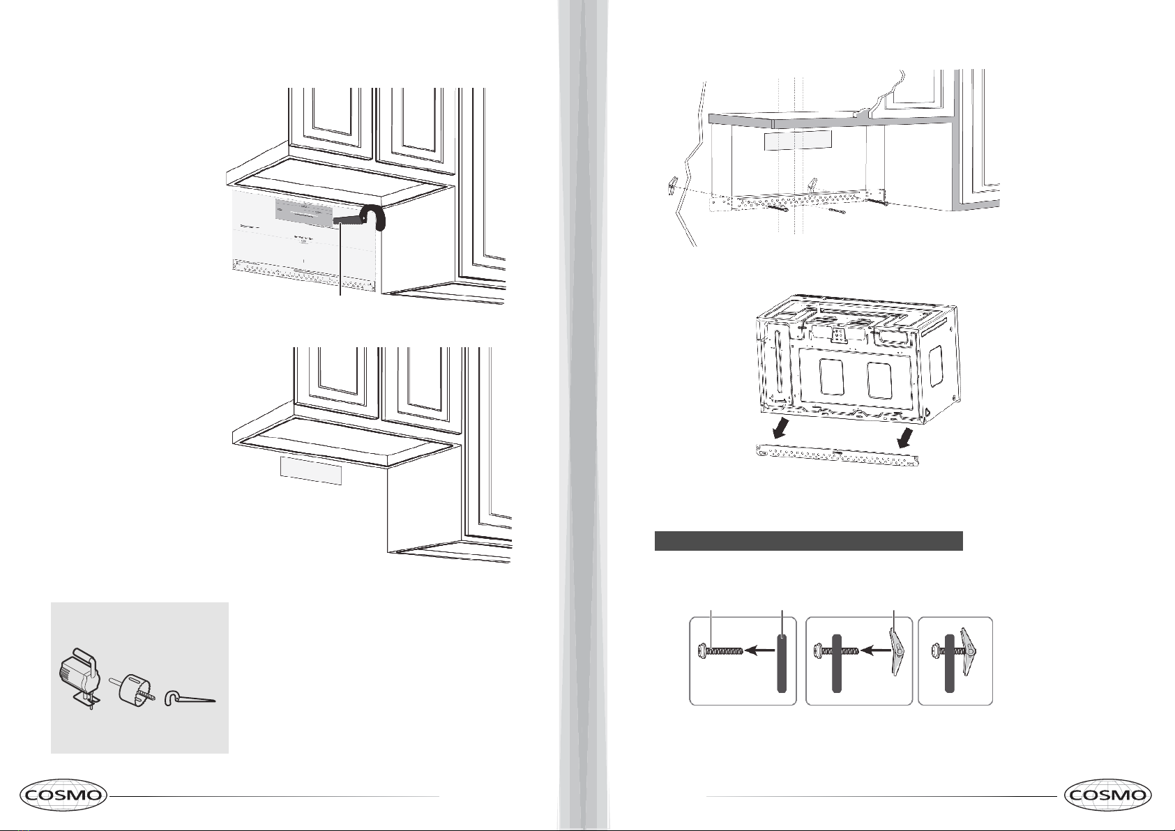
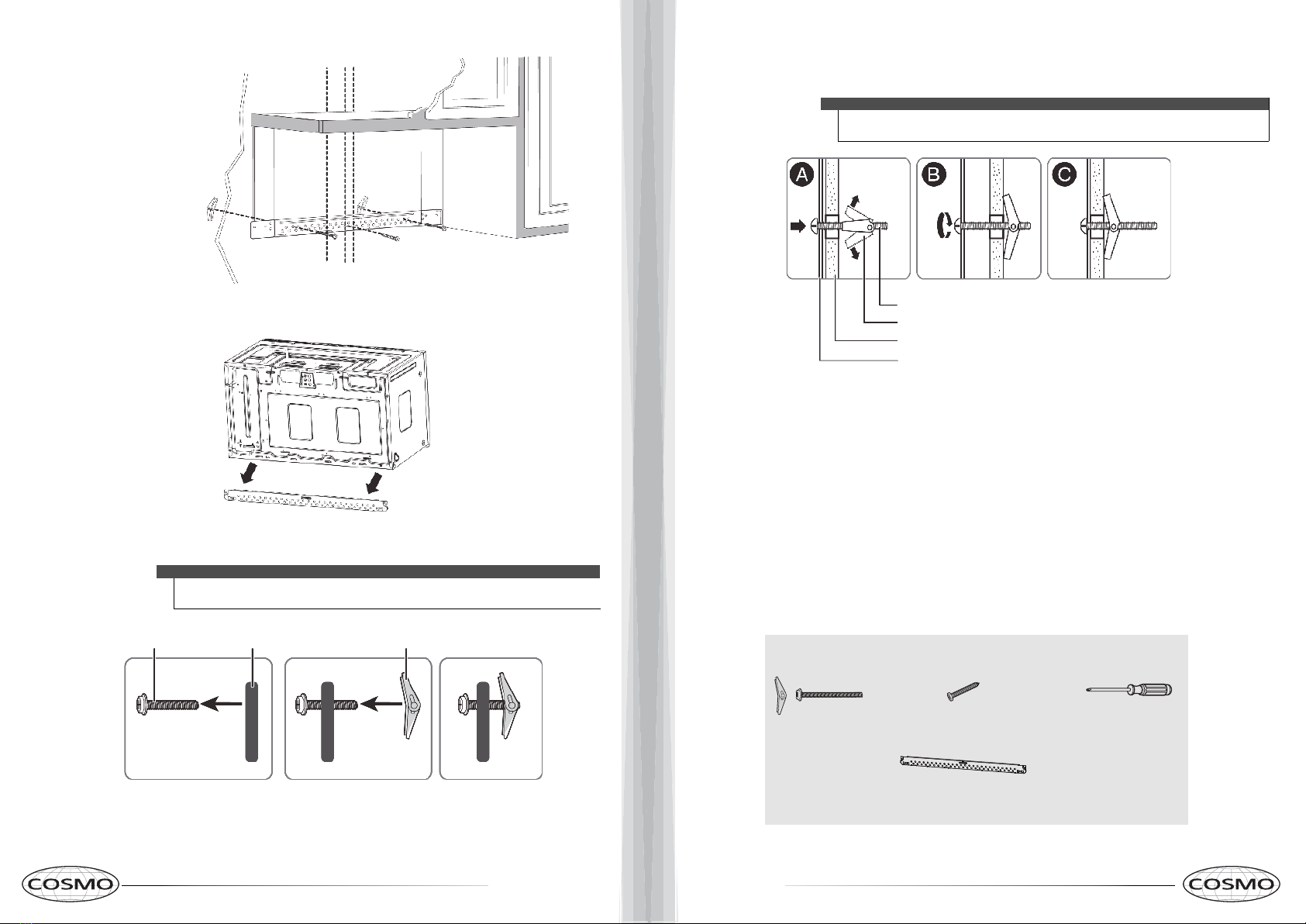
Removing your microwave
1Remove the documentation, filters, glass tray, and hardware bag from
the box. Do not remove the Styrofoam protecting the front of your mi-
crowave.
2Fold back all four box flaps, then carefully roll the microwave and box
over onto the top side. The microwave should be resting in the Styro-
foam.
3Pull the box up and off the microwave.
4Remove and throw away the plastic bags.
Styrofoam
Box
Installing your microwave
Step 1: Find the wall studs
1Using an edge-to-edge stud finder, locate the edges of the
wall stud(s) within the opening.
2Mark the center of each stud, and then draw a vertical line
down the center of each stud.
Warning
Your microwave must be connected to at least one wall stud.
The center of any adjacent wall studs should be 16" or 24" from this mark.
Wall
stud
Center of the
wall stud
Warning
You’ll need:
Edge-to-edge stud finder Ruler or tape measure Pencil
12 13
3Draw a horizontal line at the height of the front of your cabinet. This is where the top of your template will
be. If the bottom of your cabinet is flat, make sure that you leave space for the power cord.
4Trim the rear wall template along the dotted line.
Step 2: Align the rear wall template
If the rear wall template is damaged or unusable, see “Rear wall template
dimensions” on page 40 for dimensions.
Notes
• If installing the microwave beneath smooth, flat cabinets, make sure that you
leave enough space for the power cord clearance.
• If cabinets have decorative trim that interferes with the microwave installation,
remove the trim to install the microwave properly and to make sure that it is level.
Rear wall template
Power cord
Cabinet
Cabinet
Cabinet Cabinet
WALL
WALL
WALL
Flat bottom: Front overhang: Recessed back:
NOTE:
1Use a level to make sure that the bottom of the cabinet is level.
2Draw a vertical line down the center of the wall in the mounting space.
This is where the center of your template will be.
5Tape the template in place so that it is centered on the vertical line and
the top edge is aligned with the horizontal line.
Vertical line in the center
Top of the template aligned
with the horizontal line
6Find a hole that aligns with a stud (this is Cor D).
CAUTION
You must mount to at least one stud.
7Drill holes through the template at points A,B, and Cor D. If the hole lines up
with a stud, drill a 3/16” hole. Otherwise, drill a 5/8" hole for the toggle bolts. You
must use at least three holes for mounting.
Note: Depending on your stud locations, your installation may look
different. You should mount to at least one stud.

14 15
Option A - Outside top exhaust (vertical duct): See page 14
Option B - Outside back exhaust (horizontal duct): See page 23
Option C - Recirculating (non-vented/ductless): See page 33
Step 3: Select a ventilation type
This microwave is designed for three types of ventilation. Select the type of ventilation you want to use, then go to
the corresponding page.
Note
This microwave is shipped assembled for recirculating ventilation.
Adapter
*Requires a charcoal
filter (included)
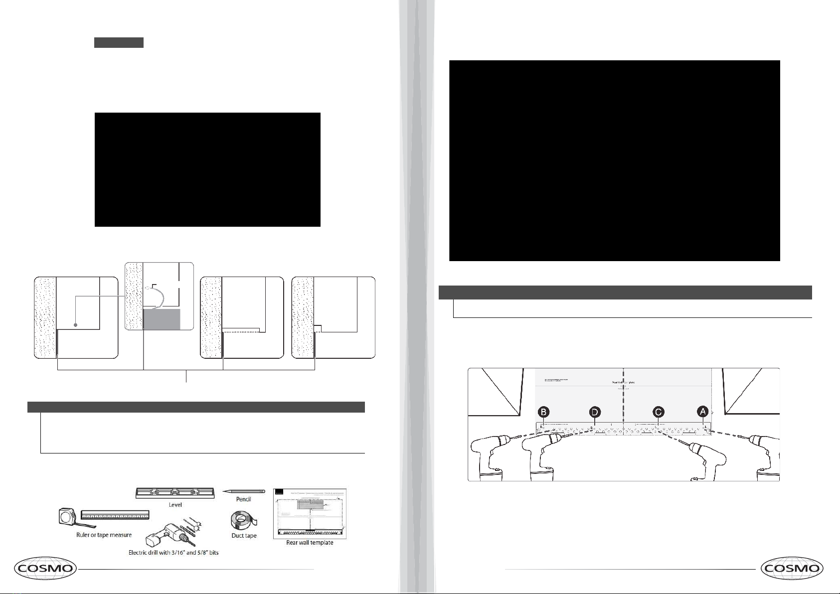
Step 4: Option A - Attach the mounting plate to the wall
1Remove the rear wall template.
2Remove the mounting plate from the back of your microwave using a Phillips screwdriver.
3Insert the toggle bolt(s) through the front of the mounting plate into the hole(s) that are not going into a stud,
and then attach the toggle wings ¾" onto each bolt. Hold your mounting plate up to holes in your wall to
identify the correct position.
4Place the mounting plate against the wall and insert the toggle wings into the holes you drilled in the drywall.
Pull the mounting plate away from the wall to help tighten the toggle wings.
Note
The top of the mounting plate is indicated with an arrow. The mounting plate’s
hooks are on the front.
Note: Depending on
your stud locations, your
installation may look
different. You should
insert toggle bolts into
drywall and wood screws
into studs.
Bolt Wing
Mounting plate
16 17
Mounting plate
Wall
Toggle wing
Toggle bolt
You’ll need:
Wood screws
Mounting plate (Qty. 1)
(ships attached to microwave)
Toggle bolts
Phillips screwdrivers
5Insert wood screw(s) through the mounting plate and into the
hole(s) drilled in the stud(s), then tighten both the wood
screw(s) and toggle bolt(s) with a Phillips screwdriver to mount
the plate. Make sure that the plate is
centered before tightening fully.
Caution
Be careful to avoid pinching your fingers
between the back of the mounting plate
and the wall.
Step 5: Option A - Preparing the top cabinet
Notes
If the top cabinet template is damaged or unusable, see “Top cabinet template
dimensions” on page 41 for dimensions.
You need to drill holes for the top support screws, a hole large enough for the power
cord to fit through, and a cutout large enough for the exhaust adapter.
1Turn off the power to the outlet in the cabinet.
2Remove everything from the cabinet.
3Trim the Top Cabinet Template along the dotted line.
4If the bottom of your cabinet is recessed and the template is too large, trim the edges
to fit. Your template should
fit snugly inside the space with no overhang.
Note
• Make sure that you keep the left and right sides even. For example, if you need
to trim the sides by 1", cut 1/2" from the left side and 1/2" from the right side.
• Some cabinets have a small bracket or glue block between the overhang and
the underside of the cabinet bottom. Cut the template to fit around these so it
lies flat on the bottom of the cabinet.
5To position the Top Cabinet Template:
• Align the center line on the template with the center line that you drew on
the wall.
• Align the back edge of the template to the rear wall (smooth or flat bottom
cabinets) or to the back of the recess (recessed cabinets) to make sure that
the holes cut into the upper cabinet align with the holes in the top of the
microwave.
6Tape the template to the bottom of the cabinet.
7Drill ½" holes through the template at points A, B, and C.
Center line
8Cut a 2" diameter hole at point Dfor the power cord.
9Cut out the shaded area Gthrough the cabinet bottom.
CAUTION
Wear safety goggles when
drilling holes in the cabi-
net bottom.

18 19
10 If you have recessed cabinets:
• Make two filler blocks out of scrap wood pieces the size of shaded areas H.
They must be as thick as the
depth of the cabinet recess.
• Drill 5/8" holes in the filler blocks to align with points A and B.
• Align the blocks with the corresponding holes in the cabinet. They
should be at the same level as the bottom edge of the cabinet frame.
11 Remove the template.
Filler blocks
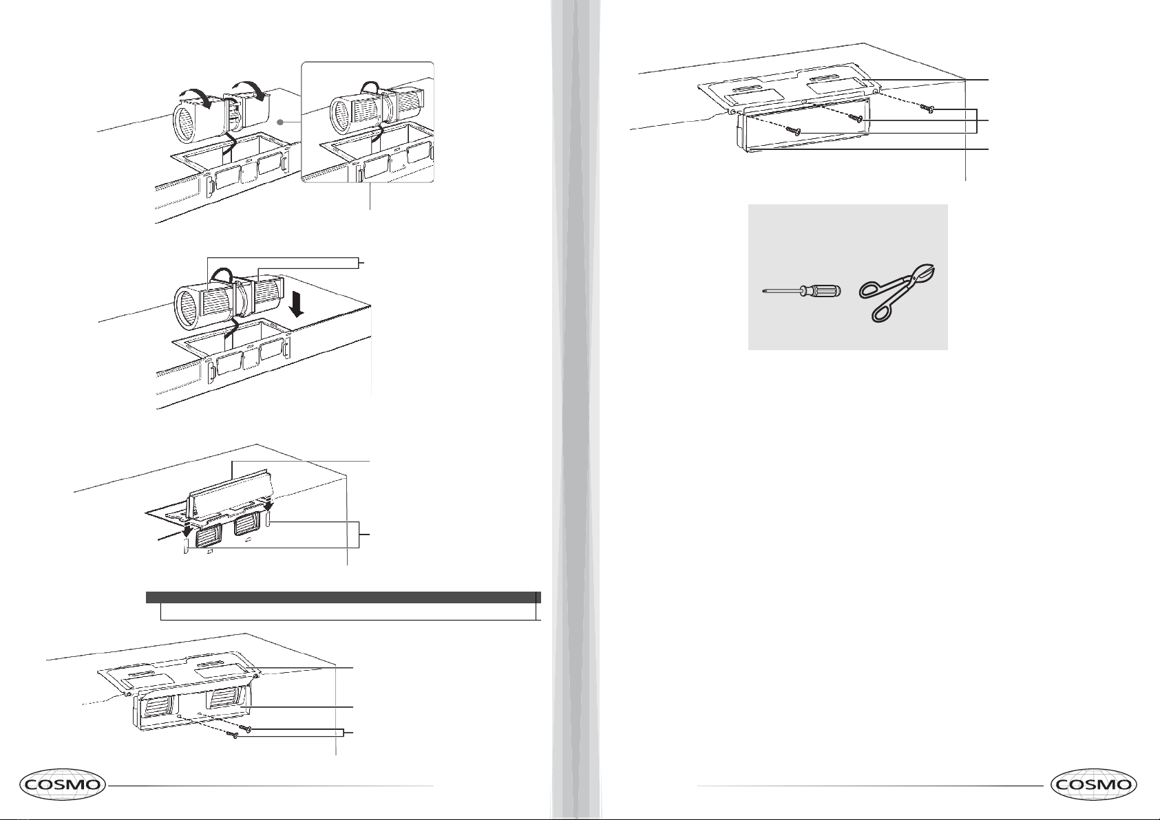
Step 6: Option A - Adapt the microwave blower for
outside top exhaust
1Remove and save the five screws that hold the blower unit in the
microwave.
2Carefully pull out the blower unit. The wires will extend far enough
to let you adjust the blower unit. Do not disconnect the wires.
Warning
Do not pull or stretch the blower unit wiring. Make sure that the wires
are not pinched.
3Turn the blower unit 90° so that the fan blade openings are facing out
the top of the microwave.

20 21
4Place the blower unit back into the opening. The blower unit exhaust
openings should face upwards.
5Slide the exhaust adapter into the guides on the top of the microwave
until it is in the locking tabs.
Fan blade openings
facing upwards
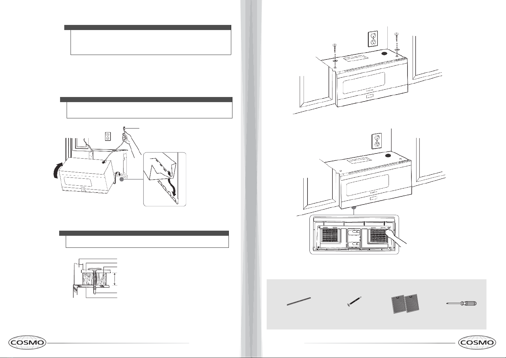
Step 7: Option A - Mount the microwave
CAUTION
•For easier installation and personal safety, we recommend that two people install this
microwave oven.
• Do not grip or use the handle during installation.
• To keep the power cord tight while mounting the microwave oven, thread the
power cord through the hole in the bottom of the cabinet.
1If your cabinet is metal, insert the nylon grommet into the power cord hole to prevent
cutting the cord.
2Lift the microwave, tilt it forward, and hook the slots on the back bottom edge onto the
four lower tabs of the mounting plate. Rotate the front of the microwave up against the bot-
tom of the cabinet.
Note
•We recommend using filler blocks if the front of the cabinet hangs below the cabinet’s
bottom shelf.
• If filler blocks are not used, damage may occur from over-tightening the screws.
Thread the power cord through the cable
hole in the top cabinet. Keep it tight
throughout steps 1-2.
3To temporarily hold the microwave in place, insert a self-aligning machine
screw through the top-center cabinet hole and rotate the screw at least
two full turns (it will be fully tightened later).
CAUTION
Be sure to keep the power cord tight. Do not pinch the cord, especially when
mounting flush to the bottom of the cabinet.
Front of cabinet
Bottom of cabinet
Filler block (optional)
Self-aligning machine screw
Top of microwave
Equivalent to depth of cabinet recess
4To attach the microwave oven to
the top cabinet, insert two self-aligning
machine screws through the holes you
drilled in the bottom of the cabinet.
Turn each screw at least two full turns
(they will be fully tightened later).
Exhaust adapter
Locking tab
Guides
6Secure the blower unit in the microwave with five of
the screws you previously removed.
Note
Make sure that the damper hinge is at
the top and that it can swing freely.
Exhaust adapter
Blower motor screw
Damper
Blower plate
Blower plate and adapter
screw
Blower plate and adapter
screws
You’ll need:
Phillips screwdrivers
Tin snips
22 23
5While holding the microwave up against the wall and cabinet, fully tighten
the top-center machine screw, then fully tighten the outer two screws.
6Fit the two grease filters into the openings underneath
your microwave.
BOTTOM
You’ll need:
Nylon grommet
(for metal cabinets)
Self-aligning machine
screws
Grease filters
Phillips screwdrivers
Step 8: Option A - Connecting ductwork
1Open the cabinet and slide the exhaust adapter front-to-back or side-to-side to adjust.
2Extend the house duct down to connect to the exhaust adapter.
3Seal the exhaust duct joints with duct tape.
4You’re finished! Skip to “Before using your microwave” on page 40.
Blower plate
Exhuast adapter
Damper
Back of microwave
House duct
You’ll need:
Duct tape
24 25
Step 4: Option B - Cutting a vent opening
1Use a saber or keyhole saw to cut out the shaded area through the rear wall.
2Remove the rear wall template.
Saw
You’ll need:
Saw
(saber, hole, or keyhole)
1Remove the rear wall template.
2Remove the mounting plate from the back of your microwave using a Phillips screwdriver.
3Insert the toggle bolt(s) through the front of the mounting plate into the hole(s) that
are not going into a stud, and then attach the toggle wings ¾" onto each bolt. Hold
your mounting plate up to holes in your wall to identify the correct position.
4Place the mounting plate against the wall and insert the toggle wings into the
holes you drilled in the drywall. Pull the mounting plate away from the wall to
help tighten the toggle wings.
Note
The top of the mounting plate is indicated with an ar-
row. The mounting plate’s hooks are on the front.
Note: Depending on
your stud locations,
your installation may
look different. You
should insert toggle
bolts into drywall and
wood screws into studs.
Bolt Mounting plate Wing
Step 5: Option B - Attach the mounting plate to the wall
26 27
5Insert wood screw(s) through the mounting plate and into the hole(s) drilled in the
stud(s), then tighten both the wood screw(s) and toggle bolt(s) with a Phillips
screwdriver to mount the plate. Make sure that the plate is
centered before tightening fully.
Caution
Be careful to avoid pinching your fingers between the back
of the mounting plate and the wall.
Mounting plate
Wall
Toggle wing
Toggle bolt
You’ll need:
Wood screws
Mounting plate (Qty. 1)
(ships attached to microwave)
Phillips screwdrivers
Toggle bolts
Step 6: Option B - Preparing the top cabinet
You need to drill holes for the top support screws and a hole large
enough for the power cord to fit through.
1Turn off the power to the outlet in the cabinet.
2Remove everything from the cabinet.
3Trim the Top Cabinet Template along the dotted line.
4If the bottom of your cabinet is recessed and the template is too large,
trim the edges to fit. Your template should fit snugly inside the space with
no overhang.
Note
• Make sure that you keep the left and right sides even. For example, if you need to
trim the sides by 1", cut 1/2" from the left side and 1/2" from the right side.
• Some cabinets have a small bracket or glue block between the overhang and the
underside of the cabinet bottom. Cut the template to fit around these so it lies flat
on the bottom of the cabinet.
5To position the Top Cabinet Template:
• Align the center line on the template with the center line that you drew on the wall.
• Align the back edge of the template to the rear wall (smooth or flat bottom cabinets)
or to the back of the recess (recessed cabinets) to make sure that the holes cut into
the upper cabinet align with the holes in the top of the microwave.
Center line
6Tape the template to the bottom of the cabinet.
7Drill ½" holes through the template at points A, B, and C.
8Cut a 2" diameter hole at point Dfor the power cord.
CAUTION
Wear safety goggles when drilling holes in the cabinet bottom.
28 29
9If you have recessed cabinets:
• Make two filler blocks out of scrap wood pieces the size of shaded areas H.
They must be as thick as the depth of the cabinet recess.
• Drill 5/8" holes in the filler blocks to align with points A and B.
Filler blocks
•Align the blocks with the corresponding holes in the cabinet. They
should be at the same level as the bottom edge of the cabinet frame.
10 Remove the template.
You’ll need:
Top Cabinet Template
Electric drill with 1/2” and 5/8”
bits
Duct tape
Scissors
(recessed cabinets only)
Safety goggles
Saw
(saber, hole, or keyhole)
Ruler or tape measure Filler blocks or scrap wood pieces
(for recessed cabinets only)
Step 7: Option B - Adapt the microwave blower for outside
back exhaust
1Remove and save the five screws that hold the blower unit in the
microwave.
2Carefully pull out the blower unit. The wires will extend far enough to let you
adjust the blower unit. Do not disconnect the wires.
Blower plate and adapter
screws
Blower motor screw
Back of microwave
Blower unit
Blower plate and adapter
screw
Warning
Do not pull or stretch the blower unit wiring. Make sure that the wires are not
pinched.
3Cut out the vent holes with tin snips.
Blower unit
Vent hole covers
30 31
4Turn the blower unit 180° so that the fan blade openings are facing out the back of the microwave.
5Place the blower unit back into the opening. The blower unit exhaust openings should match the exhaust
openings on back of the microwave.
6Slide the exhaust adapter into the guides on the back of the microwave and push in until it is aligned with the
blower motor screw holes, then secure with the blower motor screws.
7Secure the blower unit in the microwave with two of the screws you previously removed.
Note
Make sure that the damper hinge is at the top and that it can swing freely.
BEFORE
AFTER
Fan blade openings facing the
back
Exhaust adapter
Guides
Blower motor screw
Exhaust adapter
Blower plate
8Secure the blower plate and exhaust adapter with the remaining screws you removed previously.
Blower plate and adapter
screws
Exhaust adapter
Blower plate
You’ll need:
Phillips screwdrivers
Tin snips

32 33
Step 8: Option B - Mount the microwave
CAUTION
• For easier installation and personal safety, we recommend that two people install
this microwave oven.
• Do not grip or use the handle during installation.
• To keep the power cord tight while mounting the microwave oven, thread the
power cord through the hole in the bottom of the top cabinet.
1If your cabinet is metal, insert the nylon grommet into the power cord hole to prevent
cutting the cord.
2Lift the microwave, tilt it forward, and hook the slots on the back bottom edge onto the four
lower tabs of the mounting plate. Rotate the front of the microwave up against the bottom of
the cabinet.
Note
• We recomend using filler blocks if the front of the cabinet hangs below the
cabinet’s bottom shelf.
• If filler blocks are not used, damage may occur from over-tightening the screws.
Thread the power cord through the cable
hole in the top cabinet. Keep it tight
throughout steps 1-2.
3To temporarily hold the microwave in place, insert a self-aligning machine
screw through the top-center cabinet hole and rotate the screw at least
two full turns (it will be fully tightened later).
CAUTION
Be sure to keep the power cord tight. Do not pinch the cord, espe-
cially when mounting flush to the bottom of the cabinet.
Front of cabinet
Bottom of cabinet
Filler block (optional)
Self-aligning machine screw
Top of microwave
Equivalent to depth of cabinet recess
4To attach the microwave oven to the top cabinet, insert two self-aligning
machine screws through the holes you drilled in the bottom of the cabinet.
Turn each screw at least two full turns (they will be fully tightened later).
5While holding the microwave up against the wall and cabinet, fully tighten the
top-center machine screw, then fully tighten the outer two screws.
6Fit the two grease filters into the openings underneath your microwave.
7You’re finished! See “Before using your microwave” on page 40
BOTTOM
You’ll need:
Nylon grommet
(for metal cabinets)
Self-aligning machine
screws
Grease filters
Phillips screwdrivers
34 35
Step 4: Option C - Attach the mounting plate to the wall
Note: Depending on
your stud locations, your
installation may look
different. You should
insert toggle bolts into
drywall and wood screws
into studs.
1Remove the rear wall template.
2Remove the mounting plate from the back of your microwave using a Phillips screwdriver.
3Insert the toggle bolt(s) through the front of the mounting plate into the hole(s) that are not going into a stud,
and then attach the toggle wings ¾" onto each bolt. Hold your mounting plate up to holes in your wall to
identify the correct position.
Note
The top of the mounting plate is indicated with an arrow. The mounting plate’s
hooks are on the front.
Bolt Wing
Mounting plate
4Place the mounting plate against the wall and insert the toggle wings into the holes
you drilled in the drywall. Pull the mounting plate away from the wall to help tighten
the toggle wings.
5Insert wood screw(s) through the mounting plate and into the hole(s) drilled in the stud(s), then tighten both the
wood screw(s) and toggle bolt(s) with a Phillips screwdriver to mount the plate. Make sure that the plate is
centered before tightening fully.
Caution
Be careful to avoid pinching your fingers between the back of the mounting plate
and the wall.
Mounting plate
Wall
Toggle wing
Toggle bolt
You’ll need:
Wood screws
Mounting plate (Qty. 1)
(ships attached to microwave)
Phillips screwdrivers
Toggle bolts

36 37
Step 5: Option C - Preparing the top cabinet
You need to drill holes for the top support screws and a hole large enough
for the power cord to fit through.
1Turn off the power to the outlet in the cabinet.
2Remove everything from the cabinet.
3Trim the Top Cabinet Template along the dotted line.
4If the bottom of your cabinet is recessed and the template is too large, trim
the edges to fit. Your template should
fit snugly inside the space with no overhang.
Note
• Make sure that you keep the left and right sides even. For example, if you need to
trim the sides by 1", cut 1/2" from the left side and 1/2" from the right side.
• Some cabinets have a small bracket or glue block between the overhang and the
underside of the cabinet bottom. Cut the template to fit around these so it lies flat
on the bottom of the cabinet.
5To position the Top Cabinet Template:
• Align the center line on the template with the center line that you drew on the wall.
• Align the back edge of the template to the rear wall (smooth or flat bottom cabinets)
or to the back of the recess (recessed cabinets) to make sure that the holes cut into
the upper cabinet align with the holes in the top of the microwave.
Center line
6Tape the template to the bottom of the cabinet.
7Drill ½" holes through the template at points A, B, and C.
8Cut a 2" diameter hole at point Dfor the power cord.
CAUTION
Wear safety goggles when drilling holes in the cabinet bottom.
9If you have recessed cabinets:
• Make two filler blocks out of scrap wood pieces the size of shaded areas
H. They must be as thick as the
depth of the cabinet recess.
• Drill 5/8" holes in the filler blocks to align with points A and B.
•Align the blocks with the corresponding holes in the cabinet. They
should be at the same level as the bottom edge of the cabinet frame.
10 Remove the template.
Filler blocks
You’ll need:
Electric drill with 1/2” and 5/8”
bits
Duct tape Scissors
(recessed cabinets only)
Safety goggles
Saw
(saber, hole, or keyhole)
Ruler or tape measure Filler blocks or scrap wood pieces
(for recessed cabinets only)
Top Cabinet Template
38 39
Step 6: Option C - Mount the microwave
CAUTION
• For easier installation and personal safety, we recommend that two people install
this microwave oven.
• Do not grip or use the handle during installation.
• To keep the power cord tight while mounting the microwave oven, thread the
power cord through the hole in bottom of the top cabinet.
1If your cabinet is metal, insert the nylon grommet into the power cord hole to prevent
cutting the cord.
2Lift the microwave, tilt it forward, and hook the slots on the back bottom edge onto the
four lower tabs of the mounting plate. Rotate the front of the microwave up against the bot-
tom of the cabinet.
Note
• We recomend using filler blocks if the front of the cabinet hangs below the
cabinet’s bottom shelf.
• If filler blocks are not used, damage may occur from over-tightening the screws.
Thread the power cord through the cable
hole in the top cabinet. Keep it tight
throughout steps 1-2.
3To temporarily hold the microwave in place, insert a self-aligning machine screw
through the top-center cabinet hole and rotate the screw at least two full turns (it
will be fully tightened later).
CAUTION
Be sure to keep the power cord tight. Do not pinch the cord, especially when
mounting flush to the bottom of the cabinet.
Front of cabinet
Bottom of cabinet
Filler block (optional)
Self-aligning machine screw
Top of microwave
Equivalent to depth of cabinet recess
4To attach the microwave oven to the top cabinet, insert two self-aligning ma-
chine screws through the holes you drilled in the bottom of the cabinet. Turn each
screw at least two full turns (they will be fully tightened later).
5While holding the microwave up against the wall and cabinet, fully tighten
the top-center machine screw, then fully tighten the outer two screws.
6Fit the two grease filters into the openings underneath your microwave.
7You’re finished! Skip to “Before using your microwave” on page 40.
BOTTOM
You’ll need:
Nylon grommet
(for metal cabinets) Self-aligning machine
screws
Grease filters
Phillips screwdrivers
Other manuals for COS-3016ORM1SS
1
Table of contents
Other Cosmo Microwave Oven manuals

Cosmo
Cosmo COS-3019ORM2SS User manual

Cosmo
Cosmo COS-3016ORM1SS User manual

Cosmo
Cosmo COS-BIM22SSB User manual

Cosmo
Cosmo COS-2413ORM1SS User manual

Cosmo
Cosmo COS-2413ORM1SS User manual

Cosmo
Cosmo COS-2413ORM1SS User manual

Cosmo
Cosmo COS-07CTMSSB User manual

Cosmo
Cosmo COS-12MWDSS-NH User manual

Cosmo
Cosmo COS-07CTMSSB User manual

Cosmo
Cosmo COS-12MWDSS User manual


