Coster RFG 361 User manual

1
G 521 - RFG 361 C1 Eng. 25.11.08 MZ Rev. 02
We reserve the right to make changes without notice
COSTER
GAS DETECTOR WITH
REMOTE SENSOR
• Remote sensor for detecting methane, propane-LPG, carbon monoxide (CO)
• Sensors with sensing element specific for each type of gas
• 1 SPDT voltage-free output relay
• Adjustable alarm threshold (for methane and propane-LPG)
• Self-diagnosis sensor fault
• Construction and operation according to
CEI EN 50194 and CEI EN 50244 for Methane and Propane LPG
CEI EN 50291 and CEI EN 50292 for CO - carbone monoxide
• Installation on DIN rail; Protection IP 40
• Power supply 230 V ~
1. APPLICATION
RFG 361 is designed for the detection of gas in spaces such as: boiler rooms, laboratories, workshops, garages.
parking silos.
According to the type of sensor connected, monitors the concentration in air of the following gases: methane,
propane-LPG, carbon monoxide.
The sensors used are selective, and so are not influenced by gases other than that for which they are dedicated.
They have the following characteristics:
– methane and propane-LPG: sensors with semiconductors rendered selective by means of special filters,
– carbon monoxide (CO): the sensor is an electrochemical cell with two electrodes specific for CO.
The detector provides as outputs a pre-alarm signal and an alarm signal
• exceeding the pre-alarm threshold is indicated visibly by a flashing light.,
• exceeding the alarm threshold is indicated by visible and acoustic warnings and, by means of an output relay,
permits making an operational intervention such as, for example:
– closing a N.C. shut-off valve,
– closing a N.O. shut-off valve,
– switching on an aeration fan,
–sending an alarm signal to a remote site.
RFG 361 C1 Eng.
Code Description Gas Sensing element
"SELECTIVE"
Protection Data
sheet
SRD 150
SRD 250
SRD 350
SRS 150
SRS 250
SRS 350
Sensor in domestic enclosure
Sensor in industrial enclosure
methane
propane-LPG
carbon monoxide
methane
propane-LPG
carbon monoxide
Figaro TGS 2611-E00
Figaro TGS 2610-D00
Sixth-Sense ECO-Sure/2e
Figaro TGS 2611-E00
Figaro TGS 2610-D00
Sixth-Sense ECO-Sure/2e
IP 30
IP 30
IP 30
IP 44
IP 44
IP 44
–
–
–
–
–
–
2. GAS DETECTING SENSORS
G 521
25.11.08 MZ
Rev. 02

2
G 521 - RFG 361 C1 Eng. 25.11.08 MZ Rev. 02
We reserve the right to make changes without notice
COSTER
5. TECHNICAL DATA
Power supply 230 V ~ ± 10 %
Frequency 50…60 Hz
Consumption 3 VA
Protection IP40
Radiodio sturbances VDE0875/0871
Vibration test with 2g (DIN 40046)
Output relay:
– switch voltage free
– maximum switched voltage 250 V ~
– maximum switched current 5 (1) A
Construction standards CEI
Enclosure DIN 3E module
Installation on DIN 35 rail
Materials:
– base Nylon
– cover ABS
Ambient temperature:
– operating 0…45°C
– storage – 25…+ 60°C
Ambient humidity Class F DIN 40040
Weight 0.250 kg
Pre-alarm & alarm intervention thresholds
(in bold type threshold with Sensitivity = 0)
Methane
– Alarm methane 0.5…0.8…1.25 %
5,000…8,000…12,500 ppm
– Pre-alarm methane 0.3…0.5…0.8 %
3,000…5,000…8,000 ppM
Propane-LPG
– Alarm-Propane-LPG 0.22…0.35…0.56 %
2,200…3,500…5,600 ppm
– Pre-alarm propane-LPG 0.14…0.22…0.35 %
1,400…2,200…3,500 ppM
Carbon monoxide (CO)
Warning: in detecting carbon monoxide (CO), the levels and
intervention times are processed and controlled by
a microprocessor. The “Sensitivity” control must
obviously be set in the “0” position.
– Carbon monoxide: “threshold + time”
< 50 ppm: no alarm
50...100 ppm: 60 minutes
100...300 ppm: 10 minutes
> 300 ppm: immediate alarm
–Carbon monoxide (CO) pre-alarm: time between
exceeding alarm threshold and alarm
3. OVERALL DIMENSIONS
1 – Protective cover for electronic components
2 – Base with transformer, relay and terminal blocks
3 – Screws for securing base and cover
4 – DIN rail securing elements
5 – DIN rail release lever
1
2
3
4
5
4. FACIA
1 – Sensitivity control knob
2 – Power LED
3 – Sensor fault or wrong connection LED
4 – Pre-alarm (flashing LED) or alarm (LED stays lit)
5 – Reset button
432
1
5
53 50.5 21

3
G 521 - RFG 361 C1 Eng. 25.11.08 MZ Rev. 02
We reserve the right to make changes without notice
COSTER
6. SITING OF DEVICE
6.1 Detector
This must be sited in a dry space which meets the relevant ambiental requirements given in section 5.
If installed in a location classified as “Hazardous” it must be installed in a cabinet for electrical equipment con-
structed according to the regulations in force for the class of danger concerned.
The controller can be mounted on a DIN rail and housed in a standard DIN enclosure.
6.2 Sensors
The correct siting of the sensor is fundamental for the correct functioning of the system. The position depends on
the type of gas to be monitored and, in particular, on its density in respect of air:
• Methane (gas lighter than air which therefore tends to rise).
Position: at a distance of 10…50 cm from the ceiling and, in any event, above doors or windows.
• Propane-LPG (gas heavier than air which tends to move downwards).
Position: at a distance of 10…50 cm from the floor.
• Carbon monoxide (CO) (gas with a density very similar to that of air and which therefore tends to diffuse
uniformly). Position: at a height of 150…200 cm from floor.
Moreover, to ensure the correct operation of the detector and to avoid useless alarms due to a casual and momen-
tary presence of gas, the sensor must NOT be positioned:
– less than 1…2 metres from boilers or water heaters,
– less than 2…3 metres from kitchen ranges and ovens,
– in spaces where air movement could be hindered (e.g. in corners or enclosed spaces),
– near to doors or windows,
– in places where dust or dirt could contaminate the sensor and so render it ineffective,
– in places subject to possible sprays of water, particularly sensors positioned near the floor,
–in places where the temperature or humidity could be outside the limits stated in "TECHNICAL DATA".
6.3 Solenoid shut-off valve
This must be installed on the gas distribution pipe, taking the following precautions:
– if possible, in a different space from the one being controlled,
– in an easily-accessible place, especially for the valves which have to be reset manually,
– if installed outside, it must be protected against the weather,
– in installations with external propane (LPG) gas tank, it must be installed downstream of the pressure-reducing
valve (30…40 mbar)..
7. ELECTRIC WIRING
IMPORTANT: the detection system must always be in operation, so that the electric power supply to the detector
must come directly from the mains supply, without the interposition of switches or other devices
which could accidentally cut it off.
To carry out the wiring, proceed as follows:
– separate the base from the cover,
– mount the base on the DIN rail and check that the securing elements (3.4) anchor it firmly,
– carry out the wiring as in the diagram and in accordance with the safety regulations, using the following
cables:
• 1,5 mm2 cross-section for power and relay control outputs,
• 1 mm2 cross-section for the sensor positioned up to a maximum distance of 50 meters; or 1.5 mm2 cross-
section for the sensor positioned up to a maximum distance of 75 meters,
– carry out the “Jumper functions” to adapt the detector to the desired type of operational control,
– switch on power (230 V~) and check its presence at terminals L and N,
– switch off power, replace cover on base and secure it with the two screws supplied(3.3)
You are advised not to insert more than two cables in a single terminal of the detector and, if necessary, to use an
external terminal block.

4
G 521 - RFG 361 C1 Eng. 25.11.08 MZ Rev. 02
We reserve the right to make changes without notice
COSTER
8. WIRING DIAGRAMS
Functions of jumpers
M-F1 – without jumper = internal and external alarms ena-
bled
with jumper = internal and external alarms disabled
F2-F3 – without jumper = relay normally energised,
with gas leak de-energised
with jumper= relay normally de-energised,
with gas leak energised
F3-F4 – without jumper= with latching of alarm with jumper
with jumper= without latching of alarm
WARNING: before changing the position of the operational
jumpers switch off power.
N. B. : the relay switch is shown in the condition of thedevice
not being powered.
B – Gas monitoring sensor
8.1 General diagram
8.2.2 Diagram of wiring with N.C. valve (230 V~)
8.2 Examples of wiring
8.2.1 Diagram of wiring with N.O. valve with manual reset
(230 V~)
B – Gas monitoring sensor
Y1 – N.O. solenoid valve with manual reset
B – Gas monitoring sensor
Y2 – N.C. solenoid valve
The normally-closed valve (without manual reset) is the prefer-
red valve for boilers and boiler rooms in general.
Its use is NOT recommended, however, where there are open
flames (e.g. gas hob) if not provided with a device for shutting
off the gas in the absence of the flame.
BGM
RFG 361
L N
B
F2F1M F3 F4
BM
G
1 2 3
Operational
control
N
230 V ~
L

5
G 521 - RFG 361 C1 Eng. 25.11.08 MZ Rev. 02
We reserve the right to make changes without notice
COSTER
8.2.3 Diagram of connection with N.C. valve with manual
reset (230 V~)
8.2.4 Diagram of connection for control of aeration fan
(230 V~)
B – Gas detection sensor
Y3 – N.C. solenoid valve with manual reset
B – Gas detection sensor
M – Aeration fan
Typical application for detecting carbon monoxide (CO)
In garages where it is necessary to change the air, but
without acoustic alarm
9. OPERATION
9.1 Switching on
When it is switched on the detector does not immediately sense gas and so does not signal the alarm for the first
two minutes of operation.
This is the time necessary for the gas-sensitive elements to become stabilised so that their detection can be con-
sidered correct and reliable. This stabilisation period is indicated by the flashing of the FAULT (6.3) and ALARM
6.4) LEDs on the facia of the detector. At the end of the stabilisation period the FAULT and ALARM LEDs, in nor-
mal situations, switch off.
9.2 Pre-alarm and alarm threshold for methane and propane (LPG)
By means of the SENSITIVITY (4.1) knob on the detector, the intervention threshold (sensitivity) can be increased
or decreased according to particular conditions of the space in which the sensor is positioned, or for specific
requirements:
– knob towards + = increase of sensitivity,
– knob towards - = decrease of sensitivity.
These adjustments, however, remain within the limits required by the regulations so it is always possible to intervene
under conditions of the maximum safety.
The intervention levels, referred to the LEL (Lower level of Explosivity) = volumetric ratio in air of combustible
gas or vapour below which an explosive mixture is not formed) for the gases methane and propane (LPG) are as
follows (the threshold values with the “Sensitivity” knob = 0 are shown in bold type):
Type of gas LEL Pre-alarm threshold Alarm threshold
methane 5%
50,000 ppm
0.3...0.5...0.8%
3,000...5,000...8,000 ppm
0.5...0.8...1.25%
5,000...8,000...12,500 ppm
propane - LPG 2.1%
21,000 ppm
0.14...0.22...0.35%
1,400...2,200...3,500 ppm
0.22...0.35...0.56%
2,200...3,500...5,600 ppm
9.3 Pre-alarm and alarm threshold for carbon monoxide (CO)
The danger of carbon monoxide (CO) does not derive from its inflammability or the danger of explosion, but from
its extreme toxicity to the human body. Moreover, its danger does not depend only on the concentration of the gas
in air, but also on the length of time a person has remained in an atmosphere in which this gas is present.

6
G 521 - RFG 361 C1 Eng. 25.11.08 MZ Rev. 02
We reserve the right to make changes without notice
COSTER
The pre-alarm and alarm levels of the sensor are determined by the processing of a microprocessor which
keeps account of the concentration of the gas in the air and of the exposure time. For this reason the “Sen-
sitivity” knob must not influence the sensor readout and must be set in “0” position.
The intervention modes of the detector are accordingly as follows:
– concentration < 0.005%(50 ppm): the safety of the persons is guaranteed for an indefinite length of time and
so the detector does not intervene,
– concentration 0.005...0.01%(50...100 ppm): within this concentration range, for 60 minutes the detector signals
a “Pre-alarm” situation and after this period switches to “Alarm”,
– concentration 0.01...0.03% (100...300 ppm): within this concentration range, for 10 minutes the detector signals
a situation of “Pre-alarm” and after this period switches to “Alarm.,
– concentration > 0.03% (300 ppm): the safety of the persons present in the space is not guaranteed. The de-
tector immediately switches to the “Alarm” condition.
The concentration values and the times taken into consideration by the detector are established allowing a large
safety margin to ensure there is no danger to the persons.
The action of the detector is of the “Dynamic” type: if the concentration passes from one level to another, the time
calculation increases or decreases as a consequence, thereby modifying the response of the detector. In particular,
if the concentration of carbon monoxide (CO) should return below 0.005% (50 ppm) for more than one minute, the
detector returns to the “Normal” condition, canceling all the times counted up to that moment and, if it has been
programmed “Without latching” will also exit from any “Alarm” condition.
9.4 Pre-alarm
If the pre-alarm threshold is exceeded, this is indicated by the intermittent lighting of the ALARM LED (4.4) on the
detector.
9.5 Alarm
When the signal exceeds the alarm threshold for more than 20 seconds (so as to have the certainty that it is not a
momentary situation or a false alarm), the detector:
– activates the internal alarm (only if without jumper M-F1),
– on the facia the ALARM LED lights and stays lit (4.4).
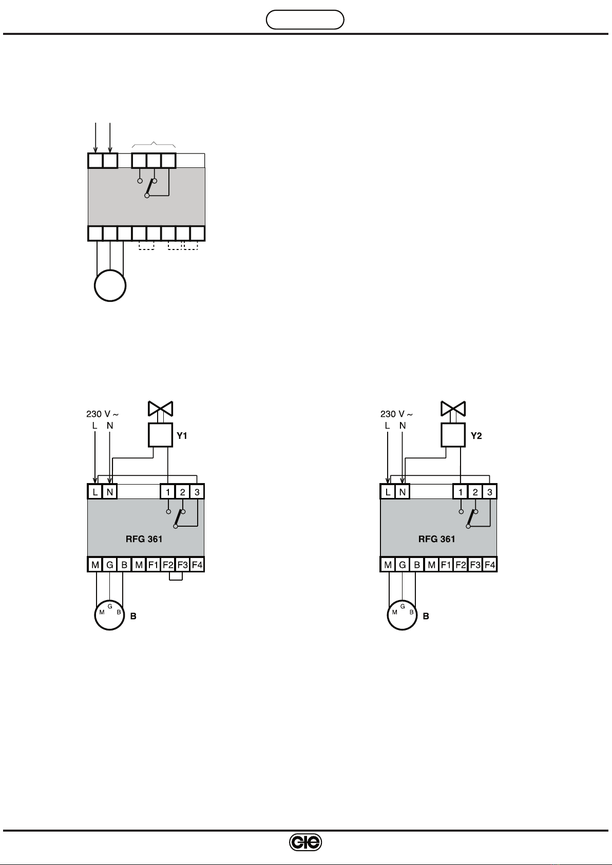
Moreover, the alarm status causes the operational control relay to act as follows:
– if normally switched off (with jumper between F2-F3): the relay is energised (switch 1-3 closes, 2-3 opens),
– if normally switched on (without jumper between F2-F3): the relay is de-energised (switch 1-3 opens, 2-3
closes).
9.6 Latching and restoration
The detector can be programmed in two ways:
• Without latching (with jumper between F3-F4):
– alarm ceases when concentration of gas returns below threshold level,
– a slow flashing (0.2 seconds On and 1 second Off) from the ALARM (4.4) signal, indicates that the alarm
triggered,
– to switch off, press RESET button (4.5) .
• With latching (without jumper between F3-F4):
– the alarm continues even when the concentration of gas has returned below threshold level,
– to switch off, press, for at least 5 seconds, the RESET button (4.5).
9.7 Autodiagnosis
In the event of a fault or incorrect connection of the sensor, the FAULT LED (4.3) lights or the detector goes into
“Alarm”, obviously with the lighting of the ALARM LED (4.4):
Type of fault Warning
FAULT ALARM
– Sensor fault X
– Not connected to terminal G X
– Not connected to terminal B X
– Not connected to terminal M X
– Connection G and B inverted X
– Connection G and M inverted X
9.8 Life of sensors
The typical life span of gas detection sensors, from the moment of installation, is as follows:
– for semiconductor sensors for methane and propane (LPG): 10 years
– for electrochemical cell sensor for carbon monoxide (CO): 5 years.
After these periods the life cycle of the gas sensing element becomes exhausted and so the sensor must be re-
placed.
On the sensor cover a label shows the date when it should be replaced.

7
G 521 - RFG 361 C1 Eng. 25.11.08 MZ Rev. 02
We reserve the right to make changes without notice
COSTER
10. TESTING
• Power the device: LINE LED (4.2) lights and FAULT LED (4.3) and ALARM LED (4.4) flash..
• After 1.5…2 minutes the detector is ready to acquire alarms and the LEDs FAULT (4.3) and ALARM (4.4) should
go out.
• Position the SENSITIVITY knob (4.1) on “0”..
• Since the sensors are selective, and so not influenced by gases other than that for which they are dedicated, to
simulate a gas escape it is necessary to use small gas cylinders containing specific gases at preset concentra-
tions, releasing the gas as near as possible to the detecting sensor.
Only for sensors for detecting propane (LPG) can gas from a normal cigarette lighter be used
• When the gas concentration exceeds the pre-alarm threshold the ALARM LED (4.4) flashes.
• With a delay (about 20 seconds) after exceeding the alarm threshold::
– ALARM LED (4.4) lights and stays lit. ,
– the internal alarm and the outside warnings are switched on (only if without jumper M-F1)),
– operational relay closes gas shut-off valve or switches on aeration fan.
• Stop erogation of gas. When gas concentration on the sensor returns below threshold level:
– if detector is “without latching” (with jumper between F3-F4), alarm ceases and ALARM LED (4.4) remains
with slow flashing until RESET button (4.5) is pushed.
– if detector is “with latching” (without jumper between F3-F4), alarm remains until RESET button (4.5) is pres-
sed for at least 5 seconds.
• If detector controls a valve with manual reset, it is necessary to re-open manually also the valve.
11. WARNING: IN EVENT OF ALARM!!
Combustible gases (methane and propane (LPG)
First of all it must be remembered that, in regard to the combustible gases methane and propane (LPG), most people
are able to be aware of their presence even at concentrations below the alarm level set for the detector, so that this
situation does not mean that the device is faulty and does not necessarily indicate a dangerous situation.
Carbon monoxide (CO)
Carbon monoxide (CO) is produced by the incomplete combustion of any apparatus which, in order to burn, has
to use the oxygen present in the air of the space in which it is installed.
It is absolutely without odour and so it is impossible to detect its presence: this makes it extremely dange-
rous.
The only means of being aware of the presence of carbon monoxide (CO) is, therefore, a gas detector.
What to do
For the reasons given above, and since you do not know instinctively what type of gas may have brought about a
dangerous situation, if the detector sounds the alarm, the following action should be taken:
– turn off any open flames,
– turn off all the devices running on gas,
– do not operate electric switches (since they could cause sparks),
– for methane, close the main valve of the gas supply,
– for propane (LPG) close the valve on the pipe coming from the storage tank,
– it is strongly recommended in every case, but above all in the presence of carbon monoxide (CO), to open win-
dows and doors to ventilate the spaces.

8
G 521 - RFG 361 C1 Eng. 25.11.08 MZ Rev. 02
We reserve the right to make changes without notice
COSTER
D 33164
COSTER TECNOLOGIE ELETTRONICHE S.p.A.
Sede Legale: 20132 Milano - Via San G.B. De La Salle, 4/a
E-mail: [email protected] Web: www.coster.eu
COSTER
CONTROLLI
TEMPERATURA
ENERGIA
Amministrazione e Vendita
Via San G.B. De La Salle, 4/a Tel. +39 022722121
20132 - Milano Fax +39 022593645
Ricevimento Ordini Fax +39 0227221239
Uff. Regionale Centro-Sud
Via S. Longanesi, 14 Tel. +39 065573330
00146 - Roma Fax +39 065566517
Spedizioni
Via Gen. Treboldi, 190/192 Tel. +39 0364773202
25048 - Edolo (BS) Tel. +39 0364773217
R.E.A. C.C.I.A.A. di Milano: 969861
C.F. e Num. di Iscr. al Registro Imprese
di Milano: 00856030150
P IVA IT 00542780986
Cap. Sociale € 4.864.000,00 int. vers.
ISO 9001:2000
®
THE INTERNATIONAL CERTIFICATION NETWOR K
Registration Number: IT - 34674
CSQ - Certificate N. 9115.COEE
INFORMAZIONI TECNICHE
Numero Verde
800-COSTER
800-267837
Date Revision No. Page Section Amendment description
12.03.07 MZ 01 various various Replaced SGG – SGS sensors by SRD - SRS selective sensors
Developed wiring diagrams.
Re-worded description operation with new sensors
25.11.08 MZ 02 5 - 6 9.2 Pre-alarm and alarm thresholds... Adjust CO concentration value
Amendment to data sheet
Table of contents
Other Coster Gas Detector manuals