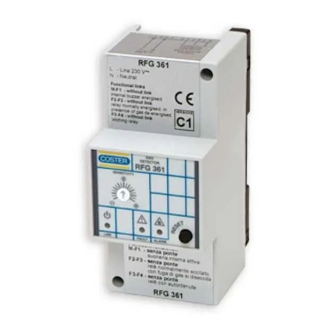
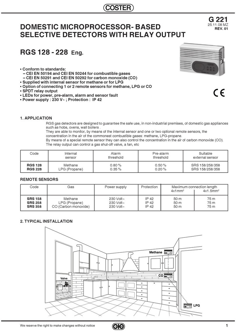
Coster RGM 122 User manual

1
G 220 - RGM 12..-22.. C1 Eng. 09.95
We reserve the right to make changes without notice
DOMESTIC GAS DETECTORS WITH
MICROPROCESSOR AND RELAY OUTPUT
G 220
09.95
RGM 122 - 128 - 222 - 228 C1 Eng.
•Power supply 220/240 V ac. or 12 V dc. Protection IP 42
• Includes internal monitoring sensor for methane (natural gas) or propane - LPG
• Possibilityofconnecting1or2remotesensorsformethane(naturalgas),propane-LPGorcarbonmonoxide
• SPDT output relay
•Alarm threshold below 25% of LEL (lower explosive limit)
•Pre-alarm threshold about 60% of alarm threshold
• Pre-alarm, alarm and sensor fault LEDs
• Construction and operation according to BSI 7348, EN 50054 and CEI-UNI/ CIG 70028
MODELS
Code Power supply Type of gas Internal Output Remote sensors
sensor SRC
RGM 128 220/240 V ac methane(naturalgas) TGS 842 SPDT relay 158 – 258 – 358
RGM 122 12 V dc methane(natural gas) TGS 842 SPDT relay 152 – 252 – 352
RGM 228 220/240 V ac propane - LPG TGS 813 SPDT relay 158 – 258 – 358
RGM 222 12 V dc propane - LPG TGS 813 SPDT relay 152 – 252 – 352
MONITORING SENSORS
Code Power supply Type of gas Internal % gas at Length connections Data
sensor 2.5 V. dc 4x1mm24x1.5mm2sheet
SRC 158 220/240 V ac methane(natural gas) TGS 842 0.8 % 50 mt. 75 mt. N 811
SRC 152 12 V dc methane(natural gas) TGS 842 0.8 % 50 mt. 75 mt. N 811
SRC 258 220/240 V ac propane - LPG TGS 813 0.35 % 50 mt. 75 mt. N 811
SRC 252 12 V dc propane - LPG TGS 813 0.35 % 50 mt. 75 mt. N 811
SRC 358 220/240 V ac carbon monoxide TGS 812 0.05 % 50 mt. 75 mt. N 811
SRC 352 12 V dc carbon monoxide TGS 812 0.05 % 50 mt. 75 mt. N 811
TYPICAL INSTALLATION
fig. 1
APPLICATION
RGM gas detectors are designed to guarantee the safe use, in
non-industrial premises, of domestic gas appliances such as :
cookers, boilers and calorifiers.
They are able to monitor, by means of an internal sensor, and,
optionally,ofoneortworemotesensors,theconcentrationinthe
airofthemostcommontypesofcombustiblegassuchas:methane
(natural gas), propane - LPG.
By means of remote sensors it is possible to monitor also the
concentration of carbon monoxide.
The output relay can control a gas shut-off valve, an aeration
fan, etc.
COSTER
COSTER
Methane (natural gas)
LPG
Valve CO
COSTER
TO SEE A SUITABLE REPLACEMENT PRODUCT
DISCONTINUED PRODUCT

2
G 220 - RGM 12..-22.. C1 Eng. 09.95
We reserve the right to make changes without notice
OPERATION
All the functions of the detector are processed by a CMOS
microprocessor.
When it is powered the detector does not signal alarms for a
period of two minutes so as to give time to the internal sensor,
and to any remote sensors used, to become stabilised. This
conditionis indicated bytheflashing of thegreen LED (fig.2.5).
Following this period the detector is ready to signal an alarm.
The internal sensor, and, if used, the remote sensors, monitor
the gas concentration level in the surrounding air and, in the
event that the pre-alarm concentration threshold is discerned
by one of the sensors, the detector causes the red alarm LED
(fig. 2.4) to flash; in the event that alarm threshold is exceeded,
the detector causes red LED to light and stay lit and, after 30
seconds, the detector also switches on audible alarm and
activates output relay.
The alarm threshold is equal to a concentration of 0.8% (8,000
ppm)ofmethane (naturalgas)in theairand 0.35%(3,500ppm)
ofpropane-LPG,whichcorrespondstoabout16%ofLEL(lower
explosivelimit). Theregulationsrequirethatthealarmthreshold
is below 25% of LEL.
LEL methane (natural gas) = 5 % (50,000 ppm);
LEL propane-LPG = 2.1 % (21,000 ppm).
Consequently,intheeventofagasleak,RGMdetectorsmakeit
possible to intervene in conditions of maximum safety.
DETECTION OF CARBON MONOXIDE
Byconnectingremote sensorSRC358orSRC352todetectorit
is possible to detect the presence of carbon monoxide. The
dangerof thisgas doesnot derivefrom itsflammability butfrom
itshightoxicityforhumansandthisdependsontheconcentration
level and time of exposure to the gas.
Concentration Time Effect
0.01 % (100 ppm) Irrelevant
0.03 % (300 ppm) 60 min. Lethargy
0.05 % (500 ppm) 90 min. Headache, nausea
0.06 % (600 ppm) 90 min. Loss of senses
0.07 % (700 ppm) 120 min. Coma, death
The alarm threshold is equal to a concentration of 0.05 % (500
ppm)of carbonmonoxide inthe airand thepre-alarm threshold
is 0.03 % (300 ppm).
WARNING LEDS
•GreenLED-Line(fig.2.5):Whendetectorispowered,thisLED
flashes for two minutes and then remains lit.
•Red LED - Alarm (fig. 2.4) : When gas concentration reaches
pre-alarm threshold this LED flashes and, when it reaches
alarm threshold, LED remains lit.
•Yellow LED - Sensor fault (fig. 2.3) : Lights up when one of the
sensors is faulty.
OUTPUT RELAY
The output relay can be used in two different ways :
•Normally not energised :
– Programmer (fig. 3.12) with switch 2 on On;
–Undernormalconditions(detectorpoweredandnotinalarm
state) the relay is not energised with contact 5-6 closed and
4-5 open;
– In alarm state, relay is energised with contact 5-6 open and
4-5 closed;
•Normally energised (BSI 7348 requirement);
– Programmer (fig. 3.12) with switch 2 on Off;
–Undernormalconditions(detectorpoweredandnotinalarm
state), relay is energised with contact 5-6 open and 4-5
closed;
–In alarm state,relay isnotenergised withcontact 5-6 closed
and 4-5 open.
LATCHING ALARM
Onceinalarmstate,if programmer(fig.3.12)hasswitch1onOn
(LatchingAlarm),thisstateremainsevenwhengasconcentration
returns below threshold level; to return to normal state it is
necessarytopressresetkey(fig.2.6)foratleastthreeseconds.
If switch 1 is on Off (without Latching Alarm), when gas
concentration returns below threshold level normal functioning
is automatically resumed.
COVER MODULE/OVERALL DIMENSIONS
fig. 2 36
▼
▼
▼
▼
80
21
130
▼
▼
3
45
6
COSTER
1 – Base module 4 – Alarm LED
2 – Cover module 5 – Line LED
3 – Sensor fault LED 6 – Reset button
CONSTRUCTION
The detector consist of two parts:
•Basemodule(fig.2.1andfig.3.1)inshockproofplasticmaterial,
suitable for wall mounting, which houses :
– Printed circuit (fig. 3.2), constructed according to Italian
Electrotechnical Committee (CEI) standards, on which are
located : terminal block for electrical connections (fig. 3.9),
programmer(fig.3.12),microprocessor(fig.3.13),resetbutton
(fig.3.14),alarmbuzzer(fig.3.11),sensingelement(fig.3.10),
transformer(fig.3.7)andairtightoutputrelaycontaininginert
gas (fig. 3.8).
– Cutout for passage of leads from rear (fig. 3.4).
–Mountingholes(fig.3.3)whichareastandarddistanceapart
andthereforesuitable for fixingto a flush-mountingpattress
if required.
– Hinge elements (fig. 3.5).
•Cover module (fig. 2.2), in shockproof plastic material, on the
faciaofwhich are the sensorfault, alarm and lineLEDs(fig. 2.
3.4.5).Thetwomodulesareattachedtoeachotherbyengaging
thecorresponding hinge elementsandby meansof securing
clip on base module (fig. 3.6) and catch on cover module.
BASE MODULE
fig. 3
1 – Base module 8 – Output relay
2 – Printed circuit 9 – Terminal block
3 – Mounting holes 10 – Sensing element
4 – Cutout for leads 11 – Alarm buzzer
5 – Hinge elements 12 – Programmatore
6 – Securing clip 13 – Microprocessore
7 – Transformer 14 – Reset button
▼
▼
83.5
6
3
9827
1
4
5
5
11
10
13
12
3
14

3
G 220 - RGM 12..-22.. C1 Eng. 09.95
We reserve the right to make changes without notice
INSTALLATION
DETECTOR
The exact siting of the detector, and of any remote sensors
used, is essential for correct functioning and depends on the
type of gas to be monitored and its density in respect of air :
Methane (natural gas) (light) : 10 to 50 cm. from ceiling
LPG (heavy) : 10 to 50 cm. from floor
Carbon monoxide : 150 to 200 cm. from floor
Itis advisabletositedetectorand anyremote sensorsused ata
certain distance from domestic appliances in order to avoid
unnecessary alarms :
Burners and calorifiers :1 to 2 metres.
Cookers :2 to 3 metres.
SHUT- OFF SOLENOID VALVE
This must be installed on the gas inlet pipe, if possible outside
the premises to be controlled, in an easily accessible place
protected from the weather.
InLPGinstallationswithanexternaltank,theshut-offvalvemust
beinstalled downstreamof thelow pressurereducing valve(30
to 40 mbar).
In LPG installations with cylinders, it must be installed
downstream of the pressure reducing valve and, if possible,
connecteddirectlytothelatterbymeansofascrewedconnector.
TECHNICAL DATA
Power supply :
– RGM 128 - 228 220/240 V ac ; 50 to 60 Hz
– RGM 122 - 222 12 V dc
Consumption 2.5 VA
Electromagnetic compatibility CEE 93/68
Output relay :
– type airtight with inert gas
– contacts SPDT voltage-free
– rated voltage 250 V
– rated capacity 5 (1) A
Audible warning 85 db
Sensing element:
– methane (natural gas) (RGM 128 -122) Figaro TGS 842
– propane - LPG (RGM 228 - 222) Figaro TGS 813
Sensor heating time 120 s
Suitable monitoring sensors :
– methane(natural gas) SRC158(220/240 Vac), SRC152(12 Vdc)
– propane - LPG SRC 258 (220/240 V ac), SRC 252 (12 V dc)
– carbon monoxide SRC358 (220/240V ac),SRC 352(12 Vdc)
Pre-alarm threshold :
– methane (natural gas) 0.5 % (5,000 ppM)
– propane - LPG 0.2 % (2,000 ppM)
– carbon monoxide 0.03 % (300 ppM)
Alarm threshold :
– methane (natural gas) 0.8 % (8,000 ppM)
– propane - LPG 0.35 % (3,500 ppM)
– carbon monoxide 0.05 % (500 ppM)
Room temperature :
– operation 0 to 40 °C
– storage – 20 to + 60 °C
Relative humidity operating 20 to 80 % at 35 °C
Protection IP 42
Weight 250 g
Dimensions 130x80x37 mm
PROGRAMMER
fig. 4
O
N1
▼
234
O
N1
▼
O
N1
▼
O
N
▼
2
O
N
▼
2
O
N
▼
34 O
N
▼
34 O
N
▼
34
Latching Alarm
With Latching Alarm Without Latching Alarm
Factory setting (fig. 3.12)
Output relay
Norm. energised Norm. not energised
Sensor connections
Internal sensor only With B2 With B2 e B3
If programmer is not adapted to actual situation of sensors,
detector signals sensor fault with yellow LED (fig. 2.3).

4
G 220 - RGM 12..-22.. C1 Eng. 09.95
We reserve the right to make changes without notice
D 33176 r.g.
WIRING DIAGRAMS
fig. 5 GENERAL LAYOUT
Relay contact is shown in condition of detector
not powered and not in alarm
EXAMPLES OF OPERATIONAL CONTROLS
The relay contacts are shown in condtion of detector not powered and not in alarm
Solenoid valve Solenoid valve Solenoid valve Fan
norm. open with reset normally closed norm. closed with reset
Without Latching Alarm With Latching Alarm WIthout Latching Alarm Without Latching Alarm
Relay norm. not energised Relay norm. energised Relay norm. energised Relay norm. energised
2
On
1
On 1
On 1
On 1
On
2
On 2
On 2
On
B1 – Internal sensor Y1 – Solenoid valve N.O. with reset
B2-B3 – SRC ... remote sensors Y2 – Solenoid valve N.C.
M – Aeration fan Y3 – Solenoid valve N.C. with reset
ELECTRICAL CONNECTION
The power lead for SRC... sensors must be parallel to that of
detector or taken singly from another point of mains network.
The electric signal leads (sensor contacts 5 and 6) must have a
cross section of 1 mm2for distances up to 50 metres and 1.5
mm2for distances up to 70 metres.
LN
Y1
220/240 V ac
12 V dc
56
124
g
56
124
g
LN
Y2
220/240 V ac
12 V dc
56
124
g
LN
Y3
220/240 V ac
12 V dc
M
LN
220/240 V ac
12 V dc
M
2 ~
LN
220/240
V ac
56
124
g
56
LN
220/240 V ac
12 V dc
124
B2
9108
Operational
control
LN
220/240 V ac
12 V dc
LN
220/240 V ac
12 V dc
B3
g
B1
56
12
g56
12
g
COSTER
CONTROLLI
TEMPERATURA
ENERGIA
COSTER
UNI EN ISO 9002
CISQ/CSQ cert.n°9115.COEE
Head Office & Sales
Tel. +39.02.2722121 (TI)
Tel. +39.02.45476193 (FW)
Fax +39.02.2593645
Reg. Off. Central & Southern
Tel. +39.06.5573330
Fax +39.06.5566517
Orders and Shipping
Tel. +39.0364.7732.00/02
Fax +39.0364.770016
E-mail: [email protected]
20132 Milan
Via San G.B. De La Salle, 4/a
00146 Rome
Viale G. Marconi, 437
25048 Edolo (BS)
Via Gen. Treboldi 190/192
Web: www.coster.info
This manual suits for next models
9
Other Coster Gas Detector manuals