Coster RGS 128 User manual

1
G 221 - RGS 128-228 Eng. 25.11.08 MZ REV. 01
We reserve the right to make changes without notice
COSTER
DOMESTIC MICROPROCESSOR- BASED
SELECTIVE DETECTORS WITH RELAY OUTPUT
G 221
25.11.08 MZ
REV. 01
RGS 128 - 228 Eng.
2. TYPICAL INSTALLATION
• Conform to standards:
– CEI EN 50194 and CEI EN 50244 for combustible gases
– CEI EN 50291 and CEI EN 50292 for carbon monoxide (CO)
• Supplied with internal sensor for methane or for LPG
• Option of connecting 1 or 2 remote sensors for methane, LPG or CO
• SPDT relay output
• LEDs for power, pre-alarm, alarm and sensor fault
• Power supply : 230 V~ ; Protection : IP 42
1. APPLICATION
RGS gas detectors are designed to guarantee the safe use, in non-industrial premises, of domestic gas appliances
such as hobs, ovens, wall boilers .
They are able to monitor, by means of the internal sensor and one or two optional remote sensors, the
concentration in the air of the commonest combustible gases: methane, LPG-propane.
By means of a special remote sensor they can also control the concentration in the air of carbon monoxide (CO).
The relay output can control a gas shut-off valve, a fan, etc
Code Internal Alarm Pre-alarm Suitable
sensor threshold threshold external sensor
RGS 128 Methane 0.80 % 0.50 % SRS 158/258/358
RGS 228 LPG (Propane) 0.35 % 0.20 % SRS 158/258/358
REMOTE SENSORS
Code Gas Power supply Protection Maximum connection length
4x1mm2 4x1.5mm2
SRS 158 Methane 230 Volt~ IP 42 50 m 75 m
SRS 258 LPG (Propane) 230 Volt~ IP 42 50 m 75 m
SRS 358 CO (Carbon monoxide) 230 Volt~ IP 42 50 m 75 m

2
G 221 - RGS 128-228 Eng. 25.11.08 MZ REV. 01
We reserve the right to make changes without notice
COSTER
6. CONSTRUCTION
The detector comprises:
– base (4.1, 5.1) in shockproof plastic, with two holes at a standard distance (5.3) for mounting on a wall or on a
standard flush- mounting pattress and with a knockout (5.4) for the passage of the electric cables.
– printed circuit (5.2), manufactured to CEI standards, where are fitted the terminal block for the electrical connections
(5.9 and 5.10), the gas sensor (5.11), the acoustic alarm (5.12), the output relay hermetically-sealed to prevent
sparks from switching comeing into contact with the surrounding atmosphere and with the switches enclosed in
inert gas to protect them from wearing out (5.8); the button for re-start from the latching condition and testing (4.6,
5.15), the microprocessor (5.14) and the programmer (5.13).
– protective cover (4.2), in shock-proof plastic, which is secured by means of two securing elements (5.5) on the left
and by the cover locking tongue (5.6) on the right.
3. TECHNICAL DATA
Power supply 230 V ~ ± 10%
Frequency 50…60 Hz
Consumption 2,5 VA
Protection IP 42
Electromagnetic compatibility CEE 93/68
Ambient temperature::
– operating 0…40 °C
– storage – 20…+ 60 °C
Permitted ambient humidity Classs F DIN 40040
Weight 250 g
SPDT output relay :
– type watertight with inert gas
– maximum switching voltage 250 V ~
– maximum switching current 5 (1) A
Acoustic alarm: 85 db / 1 metre
Time for stabilisation sensors 120 seconds
4. OVERALL DIMENSIONS
1 – Base 4 – Alarm LED
2 – Cover 5 – Power LED
3 – Sensor fault LED 6 – Button for TEST and for re-
starting operation
5. BASE
1 – Base 9 – Power supply terminal block
2 – Printed circuit 10 – Terminal block for controls
3 – Holes for fixing screws & remote sensors
4 – Knockout for cables 11 – Internal gas sensor
5 – Cover securing elements 12 – Acoustic alarm
6 – Cover locking tongue 13 – Programmer
7 – Transformer 14 – Microprocessor
8 – Output relay 15 – Button for TEST and re-start
operation
Sensing element:
– Methane (RGS 128, SRS 158):
semiconductor (Figaro TGS 2611-B00)
– LPG-propane (RGS 228, SRS 258):
semiconductor (Figaro TGS 2610-B00)
– CO (carbon monoxide) (SRS 358):
electrochemical cell (Sixth-Sense ECO-Sure/2e)
Alarm and pre-alarm thresholds:
– Methane alarm 0.80 % (8,000 ppm)
– Methane pre-alarm 60% of alarm threshold
– LPG-propane alarm 0.35 % (3,500 ppm)
– LPG-propane pre-alarm 60% of alarm threshold
– CO (carbon monoxide) alarm “threshold + time”
< 50 ppm: no alarm
50…100 ppm: 60 minutes
100…300 ppm: 10 minutes
> 300 ppm: immediate alarm
– CO (carbon monoxide) pre-alarm time between
exceeding threshold and alarm

3
G 221 - RGS 128-228 Eng. 25.11.08 MZ REV. 01
We reserve the right to make changes without notice
COSTER
7. INSTALLATION
The gas detector must be installed in the space in which a gas escape is most likely to occur e.g. the kitchen with
its hobs, oven, wall boiler.
If the gas appliances used are to be found in several rooms, it is possible to connect one or two remote sensors
to the detector (which already has an internal sensor) in order to guarantee a complete control of all the spaces
concerned.
The correct siting of the components forming the gas-detecting system is essential for ensuring its correct
operation and accordingly for guaranteeing the safety of the spaces controlled and of the persons in them.
For this reason you advised to have your system installed by a qualified engineer.
7.1 Detector and remote sensors
The siting of the detector and of any remote sensors depends on the type of gas and, in particular, on the concen-
tration in air of the gas that has to be controlled:
– Methane (a gas lighter than air that tends to move upwards). Position: at a distance of 10...50 centimetres from
the ceiling and, in any event, above the door or the highest window..
– LPG-propane (a gas heavier than air that tends to move downwards). Position: at a distance of 10...30 centimetres
from the floor,
– CO (carbon monoxide) (a gas with a density similar to air and which therefore tends to diffuse uniformly). Position:
at a height of 150... 200 centimetres from the floor.
Moreover, to ensure correct operation and to avoid false alarms due to the casual and momentary presence of gas,
the detector and the sensors must NOT be positioned :
– at a distance less than 1...2 metres from gas boilers or water-heaters.
– at a distance less than 2...3 metres from gas hobs and ovens (also to avoid contamination of the sensor by fats
and kitchen vapours.
– in the open.
– in enclosed spaces (e.g. behind curtains, in a corner or in a wardrobe).
– directly above or below a sink.
– near to doors or windows.
– near to air extractors.
– in places where temperature and humidity could be outside the limits given under 3.TECHNICAL DATA.
– in places where dust or dirt could contaminate the sensor and so render it ineffective.
– in places where air movement could be restricted by furniture.
– in places subject to water splashing, especially for detectors sited near the floor.
– in places where it would be very difficult to re-set the device manually and to make periodic checks.
7.2 Shut-off solenoid valve
This must be installed on the gas supply pipe, observing the following precautions:
– preferably in a space different from the one monitored.
– in an easily accessible place (especially for the valves which have to be re-set manually).
– if installed outside, it must be protected from the weather.
– in plants with external tanks of LPG-propane it must be installed downstream of the pressure reduction valve
(30...40 mbar).
– in plants with cylinders, it must be installed downstream of the pressure reduction valve and, if possible, connected
directly to this by means of a screwed pipe.
8. PROGRAMMER
Connection sensor
Internal sensor only With B2 With B2 and B3
If the programmer is not set according to the actual situation of
the sensors, the detector will signal fault status with the yellow
LED (3.3)
Factory setting
Output relay
Normaly energised Normaly de-energised
Latching alarm
With latching Without latching

4
G 221 - RGS 128-228 Eng. 25.11.08 MZ REV. 01
We reserve the right to make changes without notice
COSTER
10. ELECTRICAL CONNECTIONS
The power line for the remote sensors can be the same as that of the detector or taken separately from another
point in the distribution network.
IMPORTANT : the detection system must always be in operation, so the electric power for the detector and the
remote sensors must be taken directly from the mains supply, without the interposition of switches
or other devices that could inadvertently render it inactive.
For the electrical connections the following cables should be used :
– 1.5 mm2 for power supply and for the control circuit (relay output switch),
– for connection of the remote sensors :
– 1 mm2 for distances up to 50 meters,
– 1.5 mm2 for distances up to 75 meters
9. WIRING DIAGRAMS
GENERAL LAYOUT
The relay is shown with the detector in the "detector not
powered" condition
EXAMPLES OF OPERATIONAL CONTROLS
The relay is shown with the detector “powered and not in alarm” condition
Solenoid valve Solenoid valve Solenoid valve
N.O. with re-set N.C. N.C. with re-set Fan
(solution not recommended
with kitchen gas hobs)
Without latching With latching Without latching Without latching
Relay normally de-energised Relay normally energised Relay normally energised Relay normally energised
2
On
1
On
1
On
1
On
1
On
2
On
2
On
2
On
B1 – Internal sensor of detector
B2-B3 – SRS… remote sensors
M – Fan
Y1 – Solenoid valve N.O with re-set
Y2 – Solenoid valve N.C with re-set
Y3 – Solenoid valve N.C with re-set

5
G 221 - RGS 128-228 Eng. 25.11.08 MZ REV. 01
We reserve the right to make changes without notice
COSTER
11. OPERATION
11.1 Switching on
As soon as it is powered, the detector does not received alarms, and so does not signal them, for the first two mi-
nutes of operation.
This time is necessary for the gas sensing elements to become stabilised so that their readings can be considered
correct and reliable. During this period the green LED (4.5), which indicates the presence of power, lights intermittently:
at the end of the stabilisation period the green LED remains lit and the detector is ready for gas monitoring.
11.2 Pre-alarm and alarm
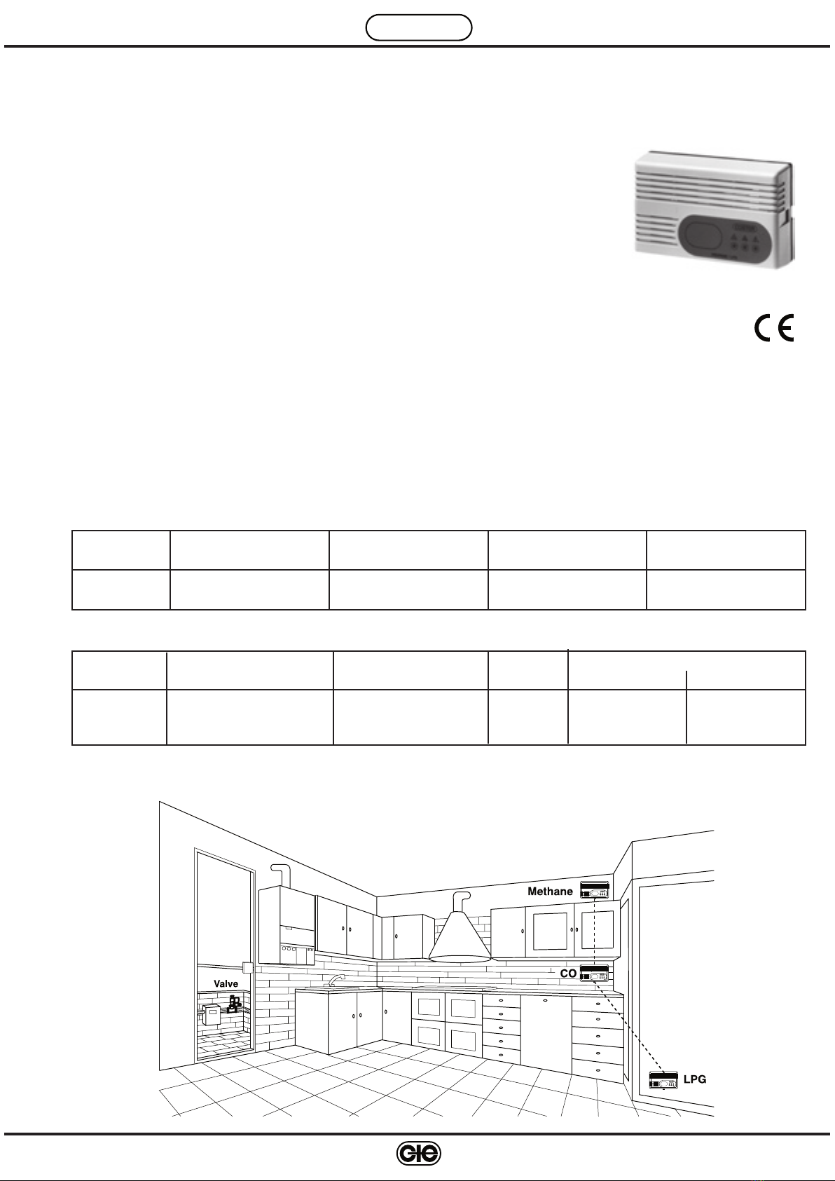
The sensing element inside the detector and those in any remote sensors (SRS 158 for methane, SRS 258 for LPG-
propane and SRS 358 for carbon monoxide (CO) monitor the concentration of gas in the air:
– should the reading by any of the sensing elements exceed the pre-alarm threshold, the red LED (4.4) on the
detector starts to flash.
– if the alarm threshold is also exceeded, the red LED lights and stays lit and, with a maximum delay of 30 seconds
(which serves to avoid signalling false alarms due to the temporary presence of gas), the detector switches on the
internal acoustic alarm and closes the output relay.
11.3 Pre-alarm threshold and alarm for combustible gases: methane & LPG-propane
For the combustible gases, methane and LPG-propane, the alarm threshold must not be greater than a concentration
equal to 20% of the LEL (lower explosive limit = volumetric ratio in air of combustible gas or vapour, below which an
explosive mixture is not formed) of the gas to be controlled (regulation UNI CEI EN 50194, point 4.3.3).
For the gases under consideration we have the following values:
Type of gas LEL Maximum threshold Alarm threshold
(20 % del LEL) set by detector
Methane 5% (50,000ppm) 1% (10,000 ppm) 0.80% (8.000 ppm)
LPG-Propane 2.1% (21,000 ppm) 0.42% (4.200 ppm) 0.35% (3.500 ppm)
The threshold for signalling the pre-alarm is established at a value equal to 60% of the alarm threshold.
11.4 Pre-alarm and alarm thresholds for carbon monoxide (CO)
Carbon monoxide (CO) can be controlled by connecting a remote sensor SRC 358 to the detector .
The danger from this gas does not derive from its inflammability or explosiveness, but from its high toxicity. This
danger depends, moreover, not only on the concentration of gas in the air but also on the length of time a person is
exposed to an atmosphere with CO present.
For this reason, it is possible to identify several intervention modes by the detector, that is:
— concentration < 0.005% (50 ppm): the safety of the persons present is assured for an indeterminate time and
so the detector does not intervene,
— concentration 0.005… 0.01% (50…100 ppm): within this concentration range the sensor and the detector for
60 minutes signal a “Pre-alarm” state; then, after this period, go to the
“Alarm” state.
— concentration 0.01…0.03% (100…300 ppm): within this concentration range the sensor and the detector, for
10 minutes, signal a “Pre-alarm” state; then, after this period, go to the
“Alarm” state.,
— concentration > 0.03% (300 ppm): the safety of the persons present is not guaranteed.
The sensor and the detector immediately signal the “Alarm” state.
The concentration values and the times taken into consideration by the sensor and, consequently, by the detector,
are established leaving a large safety margin to ensure the safety of the people present.
The action of the sensor is of the “dynamic” type: if the concentration changes from one range to another, the time
count increases or diminishes as a consequence, thereby modifying the response of the detector. In particular, if
the concentration of CO should fall below 0.005% (50 ppm) for more than one minute, the sensor returns to the
“Normal” condition, cancelling all the times counted up to that moment. As a consequence, the detector will exit
the pre-alarm condition in any event, and from the alarm state if “Without latching” is programmed (see section 8
PROGRAMMER).
11.5 Sensor fault alarm
The detector can signal the possibility that any one of the sensors, internal or external, is defective.
– if the internal sensor has a fault, on the detector facia the yellow LED flashes.
– if one of the remote sensors has a fault, both the yellow LED on the detector and the yellow LED on the defective
sensor flash.
Warning: if the warning “Sensor fault” should light, ask for technical assistance.

6
G 221 - RGS 128-228 Eng. 25.11.08 MZ REV. 01
We reserve the right to make changes without notice
COSTER
11.6 Output control
The output control consists of the SPDT switch of a relay which can be used in two ways:
– normally de-energised: under normal operating conditions (detector powered but not in alarm state), the relay is de-
energised and remains in this state even if the detector is not powered and becomes energised only in the presence
of an alarm signal.
– normally energised: under normal operating conditions (detector powered but not in alarm state), the relay
is energised and becomes de-energised in the presence of an alarm signal or when there is no power to the
detector.
The operating mode can be chosen by means of the programmer (5.13), and established in relation to the type of
control you want to use (8. PROGRAMMER).
11.7 Latching
Once the alarm has been triggered the detector can act in two ways:
– maintain the alarm status for an indefinite period until an operator intervenes. The latter must re-set manually the
operation of the detector by using the reset button (4.6, 5.15).
– maintain the alarm status until the gas concentration returns below the alarm threshold.
The operating mode can be chosen by means of the programmer (5.13), and established on the basis of the type
of operational control you want to use (8. PROGRAMMER).
12. PERIODIC MAINTENANCE
To ensure that the detector continues to operate correctly, it is necessary to check its operation according
to the instructions given below at least once every three or four months .
At least once a year it is advisable to have the system checked by a specialist engineer.
12.1 Check detector
Keep pressed the TEST button (4.6 and 5.15) for about five seconds until the detector enters first, the pre-alarm state,
and then the alarm state.
Check that:
– the red LED lights and stays lit indicating alarm status.
– the internal acoustic alarm is switched on.
– the external control signal is switched on (gas shut-off valve, fan…)
Release the button:
– if the detector is programmed “without latching”, after about five seconds the alarm ceases and the detector returns
to its normal operating condition.
– if the detector is programmed “with latching”, to exit the alarm condition press the TEST button again for about three
seconds.
– if the solenoid valve has manual re-set it must be re-opened it by means of the re-set handle,
12.2 Check remote sensor
Check that they are powered (the green LED must be lit) and that the sensing element is working (the yellow LED
should be unlit).
12.3 Length of life of sensing element
On the cover of the sensor can be seen a plate showing the servicing date of the sensor.
After this date, in fact, the life cycle of the sensing element is exhausted and it must be replaced by a new one. It is
necessary to calibrate the new sensing element and to service the sensor completely.
These operations must be carried out in the workshops of the manufacturers.

7
G 221 - RGS 128-228 Eng. 25.11.08 MZ REV. 01
We reserve the right to make changes without notice
COSTER
13. WARNING: IN THE EVENT OF ALARM
Combustible gas (Methane, LPG-Propane)
First of all, remember that most people are able to notice the presence of combustible gases (methane and LPG-
propane) in the air, even at concentrations below the alarm level established for the detector, and so the smell of gas
does not indicate that the detector is faulty and does not necessarily indicate a danger situation.
CO–Carbon monoxide
CO (carbon monoxide) is produced by the incomplete combustion of any burner that has to use the oxygen in the
air in the space in which it is installed. It is absolutely odourless and so it is impossible to detect its presence:
this renders it extremely dangerous.
Only a gas detector can reveal the presence of this gas.
For the above reasons, and since you cannot know instinctively which type of gas has caused a dangerous situation,
if the detector signals the alarm, act as follows:
– turn off all open flames, and put out cigarettes, cigars, pipes, etc;
– turn off all gas appliances;
– do not operate electric switches since these could cause sparks;
– do not use the telephone in the spaces where gas is present;
– for methane, close the central valve of the gas supply; whilst for propane-LPG close the cylinder or the storage tank.
– open windows and doors to ventilate the spaces concerned with the presence of gas.
If the cause of the alarm is discovered and securely eliminated, the detector can be re-set and the supply of gas
re-started.
If the reason for the escape of a combustible gas if not clear, immediately inform the emergency service of the gas
supply company.

8
G 221 - RGS 128-228 Eng. 25.11.08 MZ REV. 01
We reserve the right to make changes without notice
COSTER
D 33219
Amendment to data sheet
Date Revision No. Page Section Amendment description
22.12.05 MZ 4 9.WIRING DIAGRAM Amendment on WIRING DIAGRAM
25.11.08 MZ 01 5 11.4 Pre-alarm and alarm thresholds for carbon monoxide (CO) Adjust CO concentration value
COSTER TECNOLOGIE ELETTRONICHE S.p.A.
Sede Legale: 20132 Milano - Via San G.B. De La Salle, 4/a
E-mail: [email protected] Web: www.coster.eu
COSTER
CONTROLLI
TEMPERATURA
ENERGIA
Head Office & Sales
Via San G.B. De La Salle, 4/a Tel. +39 022722121
20132 - Milano Fax +39 022593645
Orders Fax +39 0227221239
Reg. Off. Central & Southern
Via S. Longanesi, 14 Tel. +39 065573330
00146 - Roma Fax +39 065566517
Shipping
Via Gen. Treboldi, 190/192 Tel. +39 0364773200
25048 - Edolo (BS) Tel. +39 0364773202
ISO 9001:2000
®
THE INTE RNATIONAL CE RTIFICATION NETWOR K
Registration Number: IT - 34674
CSQ - Certificate N. 9115.COEE
This manual suits for next models
4
Table of contents
Other Coster Gas Detector manuals
Popular Gas Detector manuals by other brands

PEMTECH
PEMTECH PT2000/H Series Operator's manual

RKI Instruments
RKI Instruments GasWatch 2 Operator's manual

Wizmart
Wizmart NB983 installation instructions

GST
GST C-9602LW-LPG Installation and operation manual

S+S Regeltechnik
S+S Regeltechnik AERASGARD AC02-SD-TYR2 Operating Instructions, Mounting & Installation

Atest Gaz
Atest Gaz SmArtGas 4 user manual