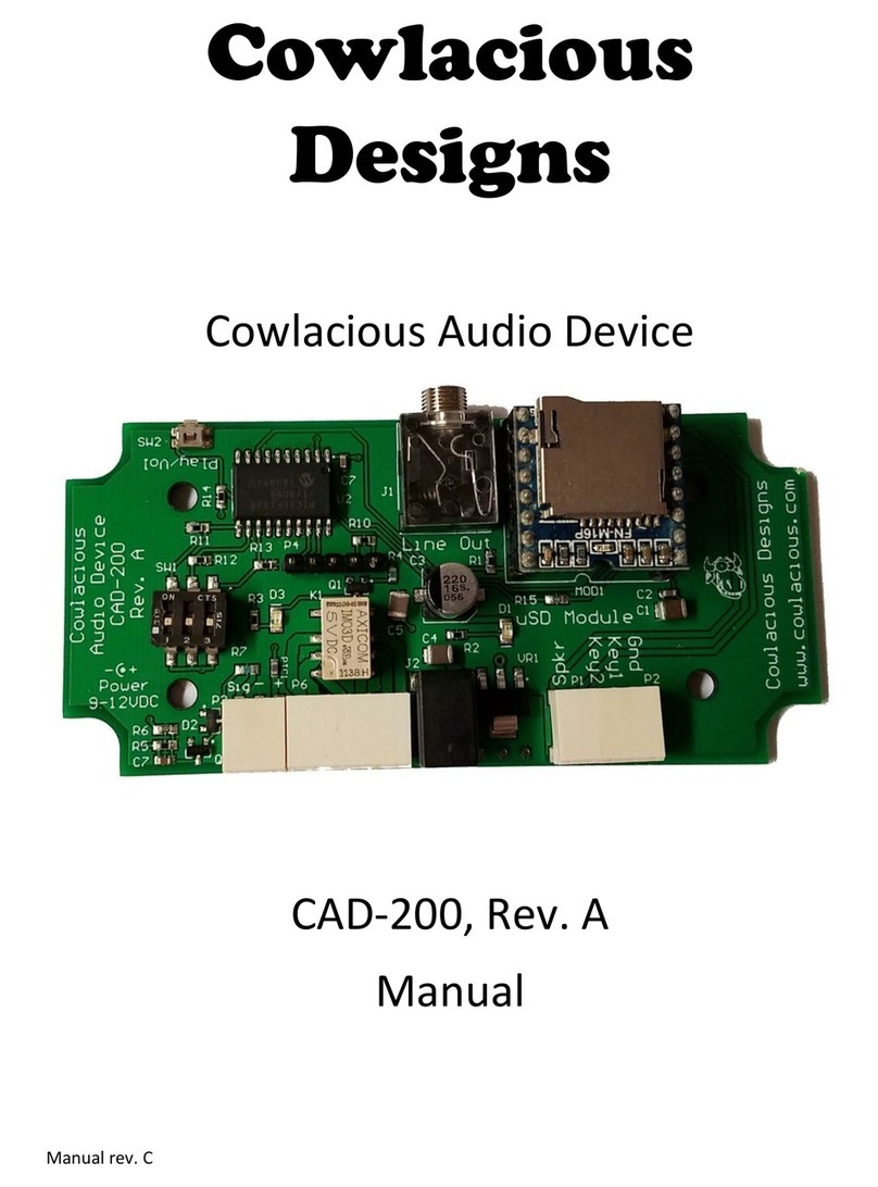
Cowlacious Designs ISD CAP 275 User manual

C
Co
m
owla
P
M
o
m
pute
Co
w
ciou
s
P
lay
e
CAP-
2
o
del: C
A
r & E
l
w
laci
o
s
IS
D
e
r Bo
a
2
75 Re
v
A
P 275
l
ectro
n
o
us D
e
D
® 1
7
ard
v
. 0
Rev. 0
nic S
e
e
sign
s
7
xxx
e
rvic
e
s
e
s

S
T
h
ba
bu
S
umm
a
h
e Cow
l
a
ck sou
n
u
tton m
o
Co
w
Figure 1
:
a
ry:
l
acious
A
n
d on an
o
de, trig
g
w
laciou
:
Top La
y
A
udio P
l
ISD 17
x
g
ered m
o
s Chip
C
y
er (Com
p
l
ayer 27
5
x
xx seri
e
o
de, or
S
2
C
order
®
p
onent Si
d
5
(CAP
e
s chip.
S
PI mo
d
®
Playe
r
d
e) of the
275) all
o
The bo
a
d
e.
r
Board
e
circuit b
o
ows yo
u
a
rd can
b
o
ard.
u
to easi
l
b
e used
i
l
y play
i
n push-

B
O
B
oard
O
pera
t
Feat
u
t
ion
u
res:
3

M
a
a
king
t
Place
a
the not
c
socket.
Conne
c
the pol
a
source
sink to
hot the
into th
e
he
p
o
w
a
17xxx
s
c
h on th
e
c
t powe
r
a
rity as
m
from 5
V
U1 if y
o
regulat
o
e
LINE
O
Th
e
w
er a
n
s
eries I
S
e
chip i
s
r
to the
P
m
arked
o
V
DC to
2
o
u are u
s
o
r is get
t
O
UT ja
c
I
M
e
Line Out j
a
n
d aud
i
S
D Chip
c
s
facing
t
P
OWER
o
n the c
i
2
4VDC,
s
ing a v
o
t
ing. Plu
c
k.
M
PO
R
a
ck should u
s
4
i
o co
n
c
order c
h
t
he sam
e
termin
a
i
rcuit b
o
though
o
ltage o
v
g a pair
R
TA
N
s
e a stereo
p
n
necti
o
h
ip into
e
way a
s
a
l block
b
o
ard. Yo
u
you ma
y
v
er 9V
D
of ampl
N
T!!!!
p
lug as pictu
r
o
ns:
the soc
k
s
the not
c
b
eing c
a
u
can u
s
y
need t
o
D
C, depe
n
ified co
m
r
ed above.
k
et. Ma
k
c
h on th
a
reful to
s
e any D
o
attach
n
ding o
n
m
puter
s
k
e sure
e
observ
e
C powe
r
a heat
n
how
s
peakers
r

5
Push Button Controls:
VOL (Volume)
Every time the volume button is pressed and released it changes the
Line-Out and SPKR volume to one of eight volume levels. The
volume levels go down and then back up in a loop, i.e. if you are on
the highest volume setting (#8), the next time you press the button it
will go down to the next highest volume setting (#7). Each press
will take the volume down until you hit level #1, then it will start
working its way back.
PLAY
Pressing the play button will begin to play the sound that has been
recorded. If you press the button during playback, it will pause the
sound and wait to be pressed again to resume. It will resume at the
start of the recording it was currently playing. The vAlert LED will
flash during playback.
Note: This is not the same as the TRIG connection or the Motion
connection. They are both controlled by the microprocessor that is
on the circuit board.
FWD (Forward)
Briefly pressing the forward button will forward the message
pointer to the next message. The forward button works in a loop. If
the unit is currently on the last message and you press FWD, then it
will forward to the first message (if there are multiple messages). If
you press play it will play the current message. If you press FWD
while the current message is playing it will skip to the next message
(if there is one) and begin to play it. If you press REC after pressing
the FWD button, it will record a new message that follows the last
message that was recorded.
Triggering Sound Playback:

6
This unit can be triggered to playback recorded sounds through three
different input triggers.
TRIG.
The TRIG input allows the unit to be triggered by any switch like device,
such as, a switch, relay contacts, a mat switch, etc. It is not designed to have
any voltage go to the trigger pins. The provided white and black wire with
the two pin header plug allows the user to easily connect their device to the
TRIG header pins.
V-Trig
The V-Trig input allows the unit to be triggered by a voltage level
trigger such as, a 5v output from a microcontroller, a 12 volt battery,
a 24 volt power source, or 120V outlet or output from a 120V
motion sensor.
The trigger voltage can be AC or DC. The polarity (which pin is
positive or which is negative) does not matter to the trigger
connection.
YOU MUST set the jumper on red shorting jumper at J6 to the
voltage level you are going to use. The 12V setting will also work
for 9V AC/DC.
Motion
The motion detector pins are designed to be used with any of the optional
motion detectors we offer for sale. This connection also provides power to
our motion sensors.

7
Trigger Message Modes
Regular Mode
No red shorting jumper on the DM or MM header pins.
The unit will play the current sound when it is triggered via the Trig,
V-Trig, or Motion trigger connections. If the trigger is still active
when it reaches the end of the message the unit will stop playing
and wait for the trigger to become inactive before it will allow itself
to be triggered again.
Dual Message Mode (DM header)
Red shorting jumper is on the DM header and no shorting jumper is
on the MM header.
This mode allows the unit to play the first message continually until the unit
receives a trigger. As soon as a trigger is received it skips to the next
message on the chip and plays it. When the trigger is over it goes back to
playing the first message on the chip. You can only have two messages
recorded on the chip for this mode to work properly.
This mode can also be used if you want a single message to continually
repeat. Use a chip that only has one message recorded on it and don’t
connect any triggering devices. The unit will continually play the message.
Multiple Message Mode (MM header)
Red Shorting jumper is on the MM header and no shorting jumper is
on the DM header.
This mode will loop through all the messages that are recorded on the ISD
chip. One message will be played each time it is triggered. After it plays the
last message it will jump back to the first message. If the trigger is
continually pressed it will play one message after another, though, we have
programmed a 3 second delay between each message playback.

Sp
e
Aux
T
h
c
o
w
h
o
p
SPI
(
T
h
f
u
o
v
h
e
w
w
Pl
e
e
cial C
o
Connect
i
h
is conn
e
o
ntrolled
b
h
enever
t
p
erate pn
e
(
Serial P
e
h
is board
u
nctions
a
v
er the S
P
e
ader co
n
w
w.cow
l
Than
k
e
ase d
o
o
nnecti
o
i
on
e
ction all
o
b
y the C
A
t
he CAP
2
e
umatics
,
e
ripheral
I
is equip
p
a
nd regist
P
I conne
c
n
nection i
s
l
acious.c
o
k
y
ou
f
o
n’t he
s
o
ns:
o
ws one
o
A
P275.
T
2
75 is pla
y
,
motors,
I
nterface
)
p
ed with
a
ers to be
c
tion. Th
e
s
availab
l
o
m/Supp
o
f
or
b
u
y
s
itate t
o
Co
m
©201
0
o
f our D
u
T
his boar
d
y
ing aud
i
or etc. w
h
)
Connec
t
a
n SPI c
o
controlle
e
manual
l
e on our
o
rt.htm
y
in
g
a
C
o
cont
a
m
puter &
E
Cowla
c
255 Distri
b
Spark
s
PH. 7
7
support@
c
www.co
0
Compute
r
8
u
al Relay
d
contain
s
i
o. It can
h
enever
a
t
ion
o
nnectio
n
d by a m
i
for contr
o
web site
C
owla
c
a
ct us
i
E
lectronic
c
ious Desi
g
b
ution Dr.
s
NV 894
4
7
5-425-91
5
c
owlaciou
s
wlacious.
c
r
& Electro
n
Boards t
o
s
2 SPD
T
be used
t
a
udio is
p
n
header t
h
i
crocontr
o
o
lling th
e
at:
c
ious
D
i
f
y
ou
h
Services
g
ns
#203
4
1
5
1
s
.com
c
om
n
ic Service
s
o
be con
n
T
relays t
h
t
o turn li
g
p
laying.
h
at allo
w
oller fee
d
e
board t
h
D
esi
g
n
s
h
ave a
n
s
n
ected to
h
at turn o
n
g
hts on/o
f
w
s all chi
p
d
ing it co
m
h
rough th
e
s
prod
u
ny
que
s
and
n
f
f,
p
m
mands
e
SPI
u
ct!
s
tions.
Other Cowlacious Designs Computer Hardware manuals
