Coxo CX235 User manual

CONTRA ANGLE
Please read this operation Manual
carefully and file for future reference.
MODEL:CX235

Thanks for purchasing our dental Contra angle!
In order to fully exert the function of this equipment, safely and
effectively use this equipment, please read this instruction carefully
before using , and please keep this manual well for reference anytime.
Under regulations'request, we have been committed to the
optimization of our product, this may cause some parts of change, when
you find the product appears some difference from description in the
manual, please contact the dealers or our after-sales center for details .
Preface
1
•Protection of liquids-normal liquids – protected equipment
•Temperatures range: - 40°C--+135°C
•Relative humidity:10% to 80%,non-condensing
•Noise:≤70dB
Technical specifications

•Please read this operation manual carefully before use and file it for future
reference .
•This product is spcialized for stomatology treatment abnormal,don’t use it in
other ways.
•This product is only for doctors.
•Every time you use it,please check first.If find anything unnormal,stop using
immediately,and contact your supplier or our after-sales center for details.
•Before operating low speed handpiece,pull contra angle handpiece with
hand to make sure handpiece connect firmly and safely.
•Head can not running without insert bur,otherwise head or motor would be
damaged.
•Ensure working pressure before running,Air pressure for four bole air motor
is 0.3Mpa,for two hole air motor is 0.25Mpa.
•Don’t immerse handpiece in any chemical solvent or solution or by dry-heat
disinfection.Sterilization by autoclave at(135±2)°C&0.22MPa is sugguested.
2

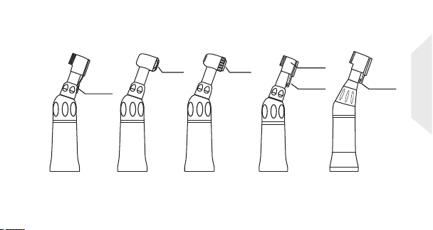
Product Composition
(CX235-1C)
Push button
Optic fiber
(CX235-1B)
Push button
Fig.1
Optic fiber
(CX235-1E)
Push button
Generator inside
1:1
1:1
1:1
LED contra angle with generator
Optic fiber contra angle
LED bulb
Inner channel1:1
Φ2 .35
Φ2 .35 Φ 2.35
Inner channel1:1
3
(CX235-1G)
1:1
contra angle
Push
button

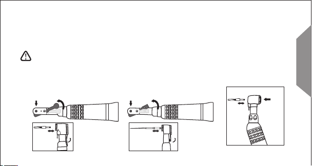
Use the attached wrench to remove the cap[Fig.2.2].
Use the bur to push out the cartidge.
Insert the new cartridge into handpiece head,being sure the small raised
part aligns the groove inside the front of the head,to insure proper fit.
Loosen the small screw on the curving part ,move the head cover and remove
the transmission gear[Fig.2.1].
Fig.2.2 Fig.2.4Fig.2.3
1:1
Cartridge Replacement
•Inner channel contra angle low speed handpiece ;
•Burs:for CA burs Φ2.35;
•Max.speed of contra angle:40000rpm
Inner channel1:1
4
Fig.2.1

Contra angle and motor connections
1. Straightly insert the motor into the connection of contra angle, until you
hear a “cracking" sound can be.
2. Hold the bending machine and pull out the motor, it will be separated[fig.3.2].
3.Alignment the groove,contra angle can insert into the air motor[fig.3.3].
Fig.3.2
optic fiber
Optic Fiber Contra angle
Bur size:Ø2.35
Optic Fiber/LED Air motor
1:1 drive
Fig.3.4
Contra angle(CX235-1B)
Bur size:Ø2.35 Air motor(CX235-3B)
1:1 drive
Fig.3.3
(CX235-1C) (CX235-3C/CX235-3D)
Fig.3.1
Contra angle with generator
(CX235-1E) Bur size:Ø2.35 Air motor(CX235-3B)
1:1 drive
Inner channel1:1
5

2.contra angle head technical parameters
Model Rotate head BUR
CX235CH-1 /2 max.40,000rpm for CA burs Φ2.35
CX235CH-3 /4 max.40,000rpm for CA burs Φ2.35
CX235CH-6 /7 max.40,000rpm for use files
CX235CH-13 max.30,000rpm forCA burs Φ2.35
360° reciprocating rotate head360° reciprocating rotate head
360° reciprocating rotate head
Fig.1.2
Fig.1.1 Fig.1.4
Fig.1.3
10.7mm
CX235CH-15/16 max.3,000rpm forCA burs Φ2.35
EXTERNAL CHANNEL
6
CX235CH-17 max.40,000rpm for CA burs Φ2.35

Fig.1.6
7
2.Special head movement technical parameters
Model Rotate head BUR
CX235CH-10 90° reciprocating for CA burs Φ2.35/prophylaxis brush
CX235CH-11 Up and down movement for CA burs Φ2.35/the crevices knife
CX235CH-12 60° reciprocating for use files
Fig.1.5
90° reciprocating rotate head
90°
Up and down mov ement
60° reciprocating rotate head
60°
Internal spray nozzle
Irrigation tube
wate r outlet wate r outlet
Inte rnal spra y nozzle
Irri gation tu be
Fig.1.8
Fig.1.7 Fig.1.9
CX235CH-9 360° reciprocating forCA burs Φ2.35/implant files
CX235CH-14 360° reciprocating forCA burs Φ2.35/implant files
EXTERNAL CHANNEL
Product Composition
4
Fig.2.4Fig.2.1
Push button
Latch plate
Fig.2.2 Fig.2.3
Push button
Latch plate
for FG burs Φ1.6.for CA burs Φ2.35 for CA burs Φ2.35 for CA burs Φ2.35
CX235C1-2 CX235C1-4 CX235C1-7 CX235C1-13
mini head
1:1 direct drive
1:1 direct drive
8
Fig.2.5
Latch plate
for CA burs Φ2.35
CX235-1F

4
Fig.2.6
Push button
Latch plate
Fig.2.7 Fig.2.8
Push button
Latch plate
for FG burs Φ1.6.for CA burs Φ2.35 for CA burs Φ2.35 for CA burs Φ2.35
Fig.2.8
CX235C2-1 CX235C2-3 CX235C2-6 CX235C2-13
mini head
•External contra angle low speed handpiece--1:1 Direct Drive
•Burs:for CA burs Φ2.35 ; for FG burs Φ1.6.
• CX235C1 Series; CX235C2 Series.
Φ2 .3 5
18°
Φ1 .6
18°
Fig.3.2
Φ1 9.6
Φ1 9.6
Fig.3.1
1:1 direct drive
9

Insert bur Switch out the rightside
1.Locking pin
Open the latch chuck,insert the bur,be sure the quadrate part of the bur
aline the proper part in the cartridge then turn the latch chuck back.
When remove the bur,open the latch chuck then take out the bur.
2.Push button
The fixed method of internal contra low speed handpiece is push button,
push the button to the end and then the bur can be get out of head.
press
Mounting of bur
Fig.3.3 Fig.3.4
Insert bur
NOTE:
1、Do not use a bending , cracking, deformation and unqualify bur. If using it,
may cause a it broken,or a flying off leading injured accident during operation
process.
2、make sure the bur lock tightly before operating.
1:1 direct drive
1 0

Product Composition
Fig.4.1 Fig.4.2 Fig.4.3
Prophylaxis
Push button
Latch plate
4:1 reduction 4:1 reduction
4:1 reduction
Fig.4.4 Fig.4.5 Fig.4.6
Latch plate Latch plate
CX235C3-13 CX235C3-10 CX235C3-11
up and down
movement
mini head
90° reciprocation
rotate
CX235C3-1 CX235C3-4 CX235C3-8
4:1 reduction
4:1 reduction
Ø5.27
1 1

Insert bur Switch out the rightside
1.Locking pin
Open the latch chuck,insert the bur,be sure the quadrate part of the bur
aline the proper part in the cartrdge then turn the latch chuck back.
When remove the bur,open the latch chuck then take out the bur.
2.Push button
The fixed method of internal contra low speed handpiece is push button,
push the button to the end and then the bur can be get out of head.
press
Mounting of bur
Fig.5.1 Fig.5.2
Insert bur
press
Insert bur
Fig.5.3 Fig.5.4
4:1 reduction
1 2

3.Prophylaxis
Mounting and Removing the Rubber Cup/Brush
Mounting
1)Insert the rubber cup/brush into a screw hole of the handpiece head.
2)Turn rubber cup/brush in a colckwise direction to fix the screw shank.
Removing
Perform a reverse procedure of Mounting. Turn the Rubber cup/brush
way of “Loosen”dirction.
rubber cup
/brush
Fig.6.1 Fig.6.2
4:1 reduction
1 3

Φ19 .6
18°
push button
hand use file 10:1reduction hand
Product Composition
10:1 Reduction
CX235C5-12
Mounting and Removing File
Insert the hand use files
press
NOTE:
1-Do not connect or disconnect the handpiece until
the drive motor has completely stopped.
2-After the file is locked in place, lightly pull
out the file to make sure the file
is locked. Fig.7.1
10:1 reduction
1 4
Fig.7

Product Composition
Fig.8.1 Fig.8.2
Push button
Latch plate
Fig.8.5 Fig.8.6 Fig.8.7
Latch plate
CX235C4-13 CX235C4-10 CX235C4-11
up and down
movement
mini head
90° reciprocation
rotate
External
spray nozzle
Latch
plate
Push
button
Push button
External
spray nozzle
16:1 Reduction
Fig.8.8
CX235C4-9 CX235C4-14
Fig.8.4
CX235C4-2 CX235C4-4
16:1 reduction
1 5

Insert bur Switch out the rightside
1.Locking pin
Open the latch chuck,insert the bur,be sure the quadrate part of the bur
aline the proper part in the cartrdge then turn the latch chuck back.
When remove the bur,open the latch chuck then take out the bur.
2.Push button
The fixed method of internal contra low speed handpiece is push button,
push the button to the end and then the bur can be get out of head.
press
Mounting of bur
Fig.9.1 Fig.9.2
Insert bur
press
Insert bur
Fig.9.3 Fig.9.4
push button
16:1 reduction
1 6
Fig.9.5

Product Composition
Fig.10.1 Fig.10.2
Latch plate
20:1
reduction 20:1 reduction
Latch plate
External
spray nozzle Push
button
20:1
reduction
MINI head
Fig.10.3
CX235C6-9 CX235C6-14 CX235C6-13
20:1 Reduction
20:1 reduction
1 7
Fig.10.4
20:1
reduction
External
spray nozzle
CX235C6-19
Insert bur Switch out the rightside
Locking pin
Open the latch chuck,insert the bur,be sure the quadrate part of the bur
aline the proper part in the cartrdge then turn the latch chuck back.
When remove the bur,open the latch chuck then take out the bur.
Mounting and Removing Bur
Insert bur Switch out the rightside
NOTE:
1-Do not connect or disconnect the handpiece until the drive motor has
completely stopped.
2-After the file is locked in place, lightly pull out the bur to make sure
the bur is locked.
Fig.11.2
Fig.11.1
push button
Fig.11.3
20:1 reduction
1 8

Mounting the”Y”type water tube
Three irrigation methods are available; External,
Internal or both External and Internal, depending
on tool and operation procedure.
External spray nozzle
irrigation Tube
(1) External Spray Nozzle
Connect the Irrigation Tube to the External
Spray Nozzle firmly. Fig.12.1
(2) Internal Spray Nozzle
Only a drill with internal irrigation is used.
1-Connect the Irrigation Tube to the Internal Spray Nozzle firmly.
2-Put the Internal Spray Nozzle into the slot on the head.
(3) External and Internal Irrigation together
Only a drill with internal irrigation is used.
1-Connect the ends of the Y-Connector to the External Spray Nozzle and
Internal Spray Nozzles refer as detailed in procedures (1) and (2).
2-Connect the Irrigation Tube to the Y-Connector firmly.
(locking pin)
1 9
Other manuals for CX235
2
This manual suits for next models
4
Table of contents
Other Coxo Dental Equipment manuals


