CP Plus Orange User manual

Network Video Recorder
User’s Manual
V1.0

Foreword
General
⚫This manual introduces the functions and operations of the NVR device (hereinafter referred to as "the
Device").
Safety Instructions
⚫The following categorizedsignal words with defined meaning might appear in theManual.
Signal Words
Meaning
DANGER
Indicates a high potential hazard which, if not avoided, will result
in death or serious injury.
WARNING
Indicates a medium or low potential hazard which, if not avoided,
could result in slight or moderate injury.
CAUTION
Indicates a potential risk which, if not avoided, could result in
property damage, data loss, lower performance, or unpredictable
result.
TIPS
Provides methods to help you solve a problem or save you time.
NOTE
Provides additional information as the emphasis and supplement
to the text.

About the Manual
⚫The manual is for reference only. If there is inconsistency between the manual and the actual product,
the actual product shall prevail.
⚫Weare not liableforany loss caused by the operations that do not complywiththe manual.
⚫The manual would be updated according to the latest laws and regulations of related regions. For
detailed information, see the paper manual, CD-ROM, QR code or our official website. If there is
inconsistency between paper manual and the electronic version, the electronicversion shallprevail.
⚫All the designsand software are subject to change without prior written notice. The product updates might
cause some differences between the actual product and the manual. Please contact the customer service
for the latest program and supplementary documentation.
⚫There still might be deviation in technical data, functions and operations description, or errors in print. If
there is any doubt or dispute,pleaserefer to our final explanation.
⚫Upgrade the reader software or try other mainstream reader software if the manual (in PDF format) cannot
be opened.
⚫All trademarks, registered trademarksand thecompany namesin the manual are the properties of their
respectiveowners.
⚫Please visit our website, contact the supplier or customer service if there is any problem occurred when
using thedevice.
⚫Ifthere is any uncertaintyor controversy, please refer toour final explanation.

Important Safeguards and Warnings
⚫The following description is the correct application method of the device. Read the manual carefully
before use to prevent danger and property loss. Strictly conform to the manual duringapplication
and keep it properly after reading.
Operating Requirement
⚫Install the PoE front-end device indoors.
⚫Thedevice doesnot support wall mount.
⚫Do not place and install the deviceinan area exposedto direct sunlight or near heat generating
device.
⚫Donot install thedevice in ahumid, dustyor fuliginous area.
⚫Keepitshorizontal installation, or install it at stable places, and prevent it from falling.
⚫Do not dripor splash liquids onto thedevice; do not put on thedevice anything filledwith liquids, in
order to prevent liquids from flowing intothe device.
⚫Install the device at well-ventilated places; do not block its ventilation opening.
⚫Use the device only within ratedinput andoutput range.
⚫Do not dismantlethe device arbitrarily.
⚫Transport, use and store thedevicewithin allowedhumidityand temperature range.
Power Requirement
⚫Make sure touse thedesignated battery type. Otherwise there may be explosion risk.
⚫Makesure to use batteriesaccording to requirements. Otherwise, it may result in fire, explosionor

burningrisksof batteries!
⚫To replacebatteries, only thesame type of batteries can be used.
⚫Makesure to dispose the exhausted batteries according to the instructions.
⚫The product shall use electric wires (power wires) recommended by this area, which shall be used
within itsratedspecification.
⚫Make sure to use standard power adapter matched with this device. Otherwise, the user shall
undertakeresulting personnel injuriesor device damages.
⚫Usepower supplythat meetsSELV (safety extra low voltage) requirements, and supply power with
rated voltage that conformstoLimited Power Source in IEC60950-1. For specificpower supply
requirements, please refer to device labels.
⚫Products with category I structure shallbe connectedtogridpower output socket, which is equipped
with protective grounding.
⚫Appliancecoupler is a disconnectingdevice. During normal use, please keep an anglethat facilitates
operation.

Table of Contents
FOREWORD
................................................................................................................................................................ 2
IMPORTANT SAFEGUARDS AND WARNINGS............................................................................................................... 4
TABLE OF CONTENTS ................................................................................................................................................. 6
1. LOCAL BASIC OPERATION ...................................................................................................................................... 7
1.12 GETTING STARTED.................................................................................................................................................7
1.12 PREPARATION.....................................................................................................................................................23
1.2 CAMERA............................................................................................................................................................46
1.2.2 REMOTE DEVICE INITIALIZATION.............................................................................................................................50
1.2.3 SHORT-CUT MENU TO REGISTER CAMERA ...............................................................................................................55
1.2.4 IMAGE ..............................................................................................................................................................56
1.2.5 ENCODE ............................................................................................................................................................58
1.2.6 CHANNEL NAME .................................................................................................................................................62
1.2.7 REMOTE UPGRADE ..............................................................................................................................................63
1.2.8 REMOTE DEVICE INFO ..........................................................................................................................................64
1.3 LIVE VIEW .........................................................................................................................................................65
1.3.1 PREVIEW ...........................................................................................................................................................66
1.3.2 NAVIGATION BAR ................................................................................................................................................66
1.3.3 PREVIEW CONTROL INTERFACE ..............................................................................................................................70
1.3.4 SEQUENCE .........................................................................................................................................................76
1.3.5 TEST TEMPERATURE .............................................................................................................................................78
1.4 PTZ..................................................................................................................................................................78
1.5 RECORD FILE ......................................................................................................................................................87
1.6 PLAYBACK AND SEARCH ........................................................................................................................................87
1.7 AI ....................................................................................................................................................................99
1.12 SETTING THE MOTION DETECTION REGION ............................................................................................................142
1.12 SETTING PERIOD ...............................................................................................................................................144
1.9 POS ...............................................................................................................................................................159
1.10 OPERATION AND MAINTENANCE ..........................................................................................................................163
1.19 FILE BACKUP ....................................................................................................................................................177
1.19 STORAGE .........................................................................................................................................................199
1.19 SYSTEM...........................................................................................................................................................208
1.19 ACCOUNT ........................................................................................................................................................213
1.16 OUTPUT AND DISPLAY........................................................................................................................................220
1.19 AUDIO ............................................................................................................................................................225
1.18 USB DEVICE AUTO POP-UP .................................................................................................................................230
1.19 SHUTDOWN .....................................................................................................................................................231
2 WEB OPERATION ............................................................................................................................................... 235
2.1 NETWORK CONNECTION.....................................................................................................................................235
2.2 WEB LOGIN .....................................................................................................................................................235
2.3 RESET PASSWORD .............................................................................................................................................236
2.4 WEB MAIN MENU ............................................................................................................................................238
3 GLOSSARY.......................................................................................................................................................... 241
APPENDIX1CYBERSECURITYRECOMMENDATIONS ................................................................................................ 243
APPENDIX 2 HDD CAPACITY CALCULATION ............................................................................................................. 345
APPENDIX 3 COMPATIBLE NETWORK CAMERA LIST ................................................................................................ 346

1. Local Basic Operation
⚫Slight difference may be found on theuser interface.The following figures for reference only.
1.12 Getting Started
⚫This chapter introduces deviceinitial settingssuch as boot up, deviceinitialization, reset password, and quick
settings.
1.1.1 Boot up
⚫Fordevice security, connect the NVR to the poweradapterfirstand thenconnect the device to the power
socket.
⚫The rated input voltage matchesthe device power button. Make sure the power wire connection is OK.Then
click the power button.
⚫Always use the stable current, if necessary, UPS is a best alternative measure. Step 1Connect the device to the
monitor andthen connect amouse.
⚫Step 2 Connect power cable.
⚫Step 3 Click thepower button at thefront or rear panel and thenboot up thedevice.After devicebootedup,
the system is in multiple-channel display mode by default.
1.1.2 Device Initialization
⚫If it is your first timeto use thedevice, set alogin password of admin (system defaultuser). You can select to
use unlock pattern tologin or not at your own choosing.
⚫For your devicesafety, keep your login password of admin well after the initialization steps, and change the
password regularly.
⚫Step 1 Boot up NVR.
The Device Initialization interface is displayed. See Figure 1-1.

⚫
⚫Figure1-1
⚫Step 2 Set system time zone according to the actual environment. Refer to Table 1-4 in "1.1.4.1.2
Date and Time" for detailed information.
⚫Clicktoshut down thedevice. It is suitable for the system integrator or theuser to shut downdirectlyafter
settingthetimezone.
Step 3 Click Next.
The Device Initialization interface is displayed. See Figure 1-2.
⚫Figure1-2

⚫Step 4 Set login password of admin. See Table 1-1.
⚫Table 1-1
Parameter
Description
User
By default, the user is admin.
Password
In the Password box, enter the password for admin.
The new password can be set from 8 characters through 32
characters and contains at least two types from number, letter and
special characters (excluding"'", """, ";", ":" and "&").
Confirm Password
Prompt Question
In the Prompt Question box, enter the information that can remind
you of the password.
On the login interface, click , the prompt will display to help you
reset the password.
⚫For your deviceownsafety, create astrong password ofyour ownchoosing. We also recommend you
change your password periodically especiallyin thehigh security system. Step 5 Click Next.
The Unlock Pattern interface is displayed. See Figure 1-3.
⚫Figure1-3
⚫Step 6 Set unlock pattern.
After set unlock pattern, the Password Protection interface is displayed. See Figure
1-4.

⚫Thepattern that youwant toset must cross at least four grids.
⚫Ifyoudo not want toconfigure the unlock pattern, click Skip.
⚫Once you have configured the unlock pattern, the system will require the unlock pattern as the default login
method. If you skip this setting, enter the password for login.
⚫Figure1-4
⚫Step 7 Set security questions. See Table 1-2.
⚫After configuration, if you forgot the password for admin user, you can reset the password through the
reserved email address or security questions. For details about resetting the password, see "1.1.3 Reset
Password".
⚫If you do not want to configure the settings, disable the email address and security questions functions on the
interface.
⚫Table 1-2
Password
Protection Mode
Description
EmailAddress
Enter the reserved email address.
In the Email Address box, enter an email address for password
reset. If you forget the password, enter the security code that you will
get from this reserved email address to reset the password of admin.
Refer to " 1.15.1.2 Modify Password" for detailed information.

Security
Questions
Configure the security questions and answers.
If you forget the password, enter the answers to the questions can
allow you to reset the password. Refer to " 1.15.3 Reset Password
" for detailed information.
⚫Step 8 Click Save tocompletethe device initialization setup.
⚫Step 9 Device goesto startup wizard interface. Refer to "1.1.4 Quick Settings" for detailed information.
1.1.3 Reset Password
⚫You can reset the password by the following methods when you forgot the password for admin account.
⚫If the passwordreset function is enabled, you can use mobile phone to scan the QR code to reset thepassword.
For details, see "1.1.3.2 ResettingPassword on LocalInterface."
⚫If the password reset function is disabled, thereare two situations:
⚫If youconfigured security questions, you can reset thepassword by the security questions.
⚫If you did not configure the security questions, you can onlyuse the reset button on the mainboardto
restore theDevice to factory default.
⚫Reset buttonis for someseries product only.
1.1.3.1 Enabling Password Reset Function
⚫After enabling password reset function, youcan scan QRcode on the local menutoreset password.
Step 1 Select Main Menu > Account > Reset Password.
The Reset Password interface is displayed. See Figure 1-5.
⚫Figure1-5
⚫

⚫Step 2 Check the boxtoenable reset function.
⚫This function is enabled by default. Step3 Click Apply toset settings.
⚫If the password reset function is disabled, you can follow the ways listed below to reset
⚫password.
⚫Device supports Reset button on the main board: You can answer the security question on the local
menu or click the Reset button on the main board to reset password. Refer to "1.1.3.3Reset Button " for
detailed information.
⚫Device does not support Reset button on the main board: You can only answer the security question on the
local menu to reset password. (Make sure you have set securityquestions).
1.1.3.2 Resetting Password on Local Interface
Step 1 Enter the SYSTEM LOGIN interface.
⚫If you have configured unlock pattern, the unlock pattern logininterfaceis displayed.
⚫See Figure1-6. Click Forgot Pattern, the password login interfaceis displayed. See Figure 1-7.
⚫Ifyoudidnot configure unlock pattern, theSystem Login interfaceis displayed.
⚫See Figure 1-7.
⚫To login from another user account, on theunlock pattern logininterface, click Switch User, oronthe
password logininterface, intheSwitch User list,selectother user tologin.
⚫Figure1-6

⚫Figure1-7
⚫Step 2Click .
⚫If you have set the reserved email address, the Prompt interfaceis displayed. See Figure1-8.
⚫Ifyoudidnot set the reservedemail address, theemail entering interface is displayed. See Figure 1-9.
⚫Enter theemail address, andthen click Next, the Prompt messageinterfaceis displayed. See Figure1-
8.
⚫Figure1-8

⚫Figure1-9
Step 3 Click Next.
The Reset Password interface is displayed. See Figure 1-10.
⚫After clicking Next, the system will collect your information for password reset, purpose and the
information includes but not limited to email address, MAC address,and device serialnumber. Read the
prompt carefullybefore clicking Next.
⚫Figure1-10
⚫

⚫Step 4 Reset thepassword.
⚫QRcode
⚫Follow the onscreeninstructionstoget thesecuritycode in your reservedemail address. In theSecurity
code box, enter the security code.
⚫You can get the securitycode twiceby scanning the same QR code. If you need to get the securitycode
once again, refresh the interface.
⚫Use the security code received in your email box to reset the password within 24 hours; otherwisethe
security code becomes invalid.
⚫Security questions
On the Reset password interface as shown in Figure 1-11, in the Reset Type list,
select Security Questions, the Security Questions interface is displayed.
If you did not configure the security questions before, in the Reset Type list, there is
no Security Questions.
⚫Figure1-11
Step 5 Click Next.
The Reset Password interface is displayed. See Figure 1-12.

1.1.3.3 Reset Button
⚫You can always use the resetbutton on the mainboard to resetthe Device to the factory default settings.
⚫Reset buttonis for someseries products only.
⚫Step 1 Disconnect the Device from power source, and then remove the coverpanel. For details about
removing thecover panel.
⚫Step 2 Find thereset button on the mainboard, and thenconnect the Devicetothepower sourceagain.
⚫Step 3 Pressandhold thereset buttonfor 5seconds to 10 seconds. See Figure 1-14 for the location of the
reset button.
⚫Figure1-14
⚫Step 4 Reboot the Device.
⚫After theDevice is rebooted, the settings have been restored to the factory default. You can start resettingthe
password.
1.1.4 Quick Settings
⚫After yousuccessfully initializedthe device, it goes to startupwizard. Here you can quickly configure your
device. Click Next, devicegoestoGeneral interface.
⚫Thestartup wizard interfaceonlydisplays after you first loginthedevice and have set theadmin password.
See Figure 1-15.
⚫

⚫Figure1-15
⚫If you select the Auto-check for updates check box, the systemwillnotifyyou automatically whenupdates
are available.
⚫After theauto-check functionis enabled, tonotify youto update timely, the system will collect the information
such as IP address, devicename, firmwareversion, and deviceserial number. Thecollectedinformation is only
used to verify thelegalityof the Device and pushupgradenotices.
⚫If you cancel the Auto-check for updates check box, the system will not perform automatic
checks.
1.1.4.1 General
⚫You can set NVR basicinformationsuch as system date, holidayand etc. You can alsoconfigure general
settings by selecting Main Menu > SYSTEM > General.
1.1.4.1.1 General
⚫You can set devicebasicinformation such as device name, serialnumber.
Step 1 Click Next.
⚫TheGeneral interfaceisdisplayed. SeeFigure 1-16.

⚫Figure1-16
⚫Step 2 Set parameters. See Table 1-3.
⚫Table 1-3
Parameter
Description
Device Name
In the Device Name box, enter the Device name.
Device No.
In the Device No. box, enter a number for the Device.
Language
In the Language list, select a language for the Device system.
Video Standard
In the Video Standard list, select PAL or NTSC according to your actual
situation.
Sync to Remote
Device
Enable this function; the NVR can synchronize information with the
remote device such as Language, video standard, time zone.
Instant Play (Min.)
In the Instant Play box, enter the time length for playing back the
recorded video. The value ranges from 5 to 60.
On the live view control bar, click the instant playback button to play back
the recorded video within the configured time.
Auto Logout (Min.)
In the Auto Logout box, enter the standby time for the Device. The
Device automatically logs out when it is not working for the configured
time period. You need to login the Device again.
The value ranges from 0 to 60. 0 indicates there is not standby time for
the Device.
Click Monitor Channel(s) when logout. You can select the channels
that you want to continue monitoring when you logged out.
IPC Time Sync
Syncs the Device time with IP camera.

Parameter
Description
IPC Time Sync
Period (hour)
In the IPC Time Sync Period box, enter the interval for time sync.
Auto logout
You can set auto logout interval once login user remains inactive for a
specified time. Value ranges from 0 to 60 minutes.
Navigation Bar
Enable the navigation bar. When you click on the live view screen, the
navigation bar is displayed.
Mouse Sensitivity
Adjust the speed of double-click by moving the slider.
The bigger the value is, the faster the speed is.
⚫Step 3 Click Next buttontosave settings.
1.1.4.1.2 Date and Time
⚫You can set devicetime.You can enable NTP (Network Time Protocol) function so that the device can
synctime with the NTP server.
You can also configure date and time settings by selecting Main Menu > SYSTEM >
GENERAL > Date &Time.
Step 1 Click Date & Tim tab. See Figure 1-17.
⚫Figure1-17
⚫Step 2 Configurethe settings for dateand time parameters. See Table 1-4.
Other manuals for Orange
3
Table of contents
Other CP Plus DVR manuals
CP Plus
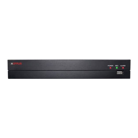
CP Plus CP-RMC-D12 User manual
CP Plus
CP Plus Indigo JRC-27F User manual
CP Plus
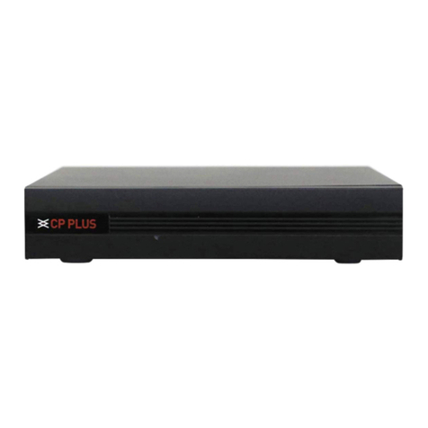
CP Plus Indigo User manual
CP Plus
CP Plus 4/8/16 Channel DVR User manual
CP Plus
CP Plus Cosmic User manual
CP Plus
CP Plus Orange User manual
CP Plus
CP Plus CP-UNR-4K2042-V2 User manual

CP Plus
CP Plus CP-UNR-4K2082-V2 User manual

