XTS 532 User manual

Quick Start Guide NVR 532
www.xtscorp.com

Network Video Recorder
Quick Start Guide
1.Notes
●Please read this instruction carefully for correct use of the product and preserve it for reference purposes.
●There may be several technically incorrect places or printing errors in this manual. The updates will be added into the new version of
this manual. The contents of this manual are subject to change without notice.
●This device should be operated only from the type of power source indicated on the marking label. The voltage of the power must be
verified before using the same. Kindly remove the cables from the power source if the device is not to be used for a long period of time.
2.HDD Installation
This series of the product supports 8 SATA hard drives. Please make sure that the device is powered off before the installation.
●All the examples and pictures used here are for reference only.
3. Rear Panel Instructions
The interface of the rear panel is for reference only.
1
①Loosen the screws to open the cover. ③Screw HDD under the lower mounting bar.
⑥Install back the upper mounting bar.
Install back the cover.⑨
⑤Install other three lower HDDs.
Install other three upper HDDs.⑧
②Loosen the upper mounting bar.
④Connect the power and data cables.
⑦Screw HDD under upper mounting
bar.
Rear Panel
Note: There may be only one mounting bar for some models. Thus, only four HDDs can be installed under the mounting bar,
just like step 5.

4. Startup & Shutdown
► Startup
① Connect the monitor and the power.
② The device will boot and the power indicator will display blue.
③ A wizard window will pop up.
► Shutdown
By IR remote controller – Press power button to see a shutdown window. The device will shut down by selecting “OK” button. Then
disconnect the power.
By mouse – Go to “Main Menu” and then select “Shutdown” icon. This will bring up a shutdown window. The device will shut down by
clicking “OK” button. Then disconnect the power.
Descriptions
Name
Audio In
Audio Out
K/B
Alarm In Alarm inputs for connecting sensors
GND Grounding
Alarm Out
Relay output; connect to external alarm
Connect to keyboard. A is TX+, B is TX-
Audio ouput; connect to the sound box
For two-way talk; connect to active pickups
2
Connect to high-definition display device
VGA output; connect to monitor
Network port
Connect to USB devices (unavailable for upgrade)
Descriptions
Name
VGA port
LAN
HDMI port
USB
Connect to external SATA HDD for backup
E-SATA
P/Z Connect to speed dome. Y is TX+, Z is TX-
5. Login
After the wizard setup, you can see the live image. Right click to pop
up a menu toolbar. Click “Main Menu” button. This will take you to see
a login box. The default username is admin; the default password is
123456. Enter username and password and click “Login” button to go
to the main menu setup.
6. Network Configuration
►LAN
① Set the network of the NVR. Go to Main Menu→Setup→Network→
Network as shown in Fig 1. Input HTTP port (the default value is 80),
server port (the default port is 6036), IP address, subnet, gateway, etc.
If using DHCP, please enable DHCP in both the NVR and the router.
② Go to Main Menu→IP Camera tab as shown in Fig 2. Click “Search”
button to search the IP cameras in the same local network (The IPC
which supports the Onvif protocol may be added manually). If the IPC
is not in the same local network as the NVR, you can select the device
and click “Setup” as in Fig 3 to modify the IP address. Please refer to
the Chapter 4 of NVR User Manual.
After you finish adding IP cameras, you can see the live images through the monitor of the NVR. You may connect the previous 16 CH
directly to the device through IPC direct connection network ports and then add the IP cameras for the remaining channels into the NVR via
WAN/LAN. The following will mainly introduce how to add the IP cameras via LAN/WAN.
(Fig 1)
IPC direct connection network ports
-
116

3
(Fig 2) (Fig 3)
③ Checkmark the device you want to add and then click “OK” button to return to the previous interface to apply the settings.
“Connected” status means connecting the device successfully and you will see the live image. You may select the added device and
click “Setup” button to modify channel, IP address as shown in Fig 5 .
(Fig 4) (Fig 5)
(Fig 6) (Fig 7)
►WAN
① Set the network of the NVR. Go to Main Menu→Setup→Network→Network as shown in Fig 6. Input static IP address or enable PPPoE
and then input the user name and password received from your ISP.
② Go to Main Menu→IP Camera tab. Click “Add” button to add the IP cameras as shown in Fig 7. Checkmark “Enable” checkbox, select
channel, manufacturer and input IP address, server port, username and password of the IP camera. Then save the settings. The IP camera
must be connected over WAN. And here the IP address of the IP camera must be a WAN IP address.
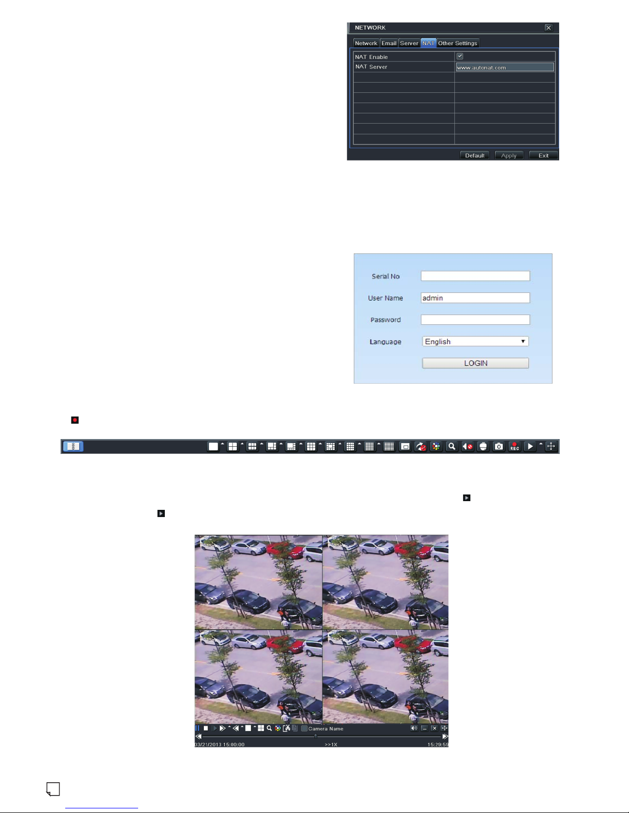
7. NAT
► NAT Settings
①The NVR shall be powered on and connected to the network.
4
9. Playback
Right click the mouse in the live interface to pop up the menu toolbar. Click the little triangle button beside button to set playback time
(eg. 5 minutes). Then click button to play back the record from the past 5 minutes.
8. Manual Recording
Before recording, please install and format a HDD. Right click the mouse in the live interface to pop up the following menu toolbar.
Click button to start recording.
(Fig 8)
►
After finishing the NAT settings, you can enter the NAT Server on the remote PC (Input http://www.autonat.com to go to the IE client).
If you are the first time to access the NAT, the network will download the ActiveX automatically. After installing ActiveX successfully,
it will pop up the login box:
NAT Access
Serial No: The MAC address of the NVR (Go to Main Menu →
Information → Network to check the MAC address of the NVR).
User Name: The username of NVR. The default username is admin.
Password: The password of NVR. The default password is 123456.
Note: The web client must be in the remote network. It cannot be in
the same local network as that of the NVR.
②Go to Main Menu→Setup→Network→Network. Refer to Fig 1.
You can obtain the IP address, subnet mask and gateway
automatically. You can also manually enter them according to the
actual network situation. Please make sure the network segment is
the same as that of the network which is used.
③Set the preferred or alternative DNS Server. Click “Apply” to
save the parameters.
④Go to Main Menu→Setup→Network→NAT tab. Refer to Fig 8.
⑤Enable NAT and input the NAT Server (The default NAT Server
is www.autonat.com). Click “Apply” to save the parameters.
Table of contents
Other XTS DVR manuals


