CPI Canada Inc. Installation 2
CHAPTER 2
INSTALLATION
CONTENTS:
2.1.0 INTRODUCTION......................................................................................................................................2-2
2.2.0 UNPACKING ............................................................................................................................................2-2
2.3.0 REMOVING THE GENERATOR COVER.................................................................................................2-2
2.4.0 MAJOR COMPONENT LAYOUT..............................................................................................................2-3
2.5.0 EQUIPMENT PLACEMENT .....................................................................................................................2-3
2.5.1 Main Cabinet.........................................................................................................................................2-3
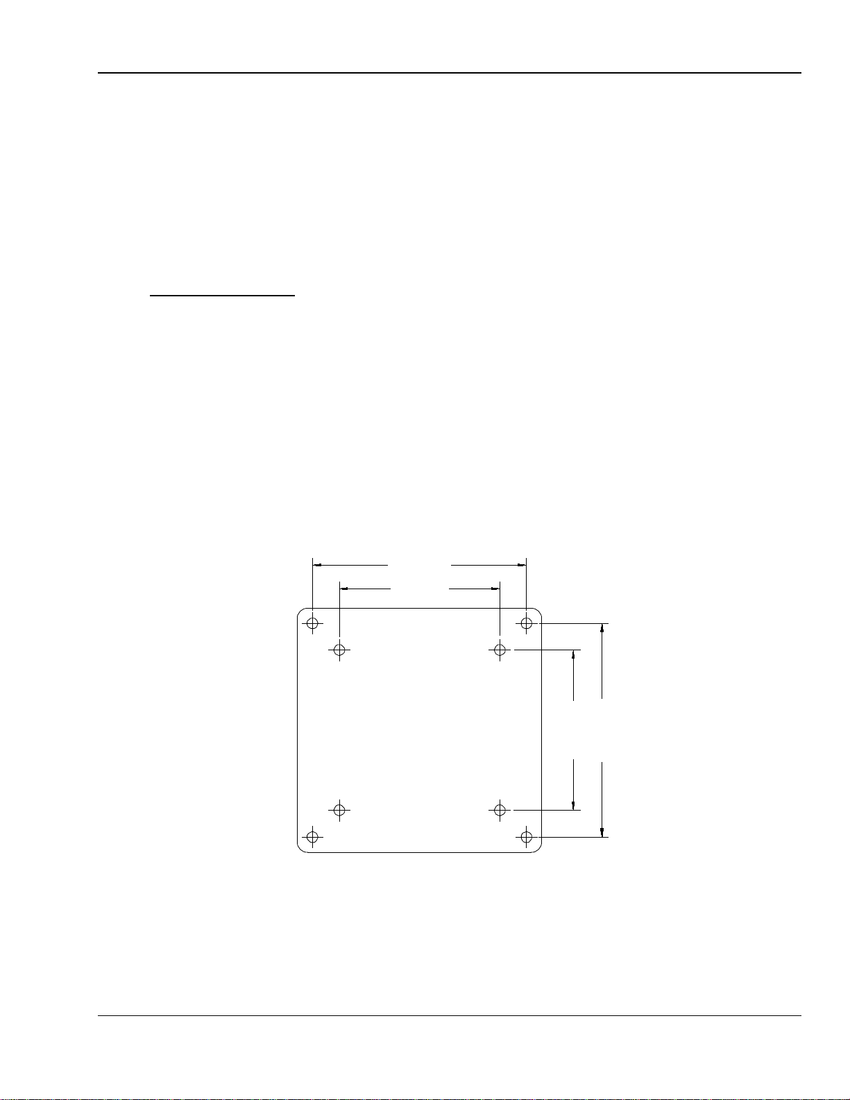
2.5.2 Control Console ....................................................................................................................................2-3
2.5.3 Anchoring the Generator to the Floor ...................................................................................................2-5
2.6.0 WIRING TO THE GENERATOR...............................................................................................................2-5
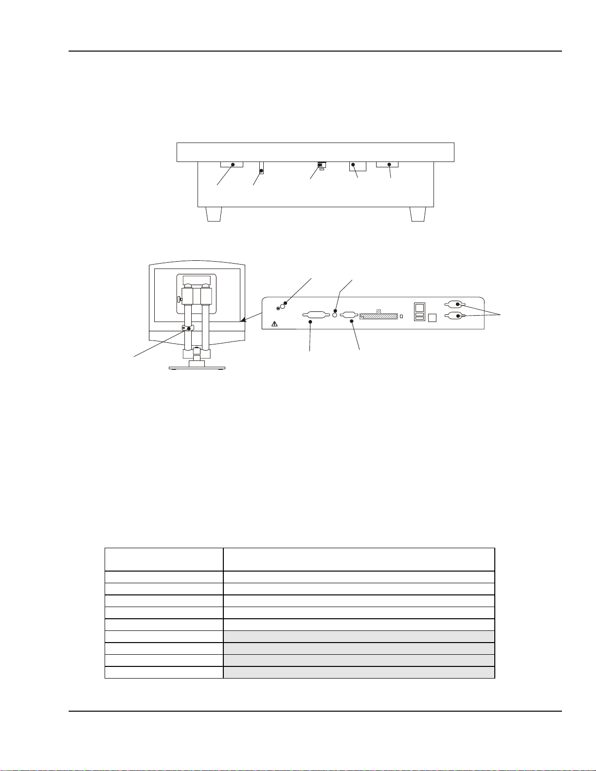
2.6.1 Control Console ....................................................................................................................................2-6
2.6.2 Hand Switch (Optional).........................................................................................................................2-9
2.6.3 X-ray Tube Stator Cable.....................................................................................................................2-10
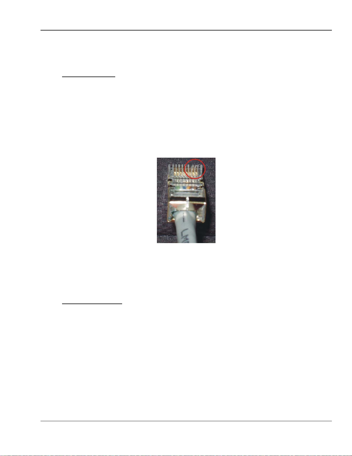
2.6.4 Checking the Connection of the X-ray Tube Stator Cable..................................................................2-12
2.6.5 Power Line Mains................................................................................................................................2-12
2.6.6 High Voltage Cables ...........................................................................................................................2-15
2.6.7 X-Ray Tube Housing Ground..............................................................................................................2-17
2.6.8 Room Equipment ................................................................................................................................2-17
2.6.9 Emergency Power Off / Power Distribution Relay ..............................................................................2-17
2.6.10 Safety Interlocks..................................................................................................................................2-17
2.7.0 LOW-SPEED STARTER TUBE COMPATIBILITY..................................................................................2-17
2.7.1 Setting 120 / 240 VAC Boost Voltage.................................................................................................2-18
2.8.0 PROGRAMMING THE DUAL-SPEED STARTER..................................................................................2-18
2.8.1 EPROM type / dual-speed starter - applies only to DSS Board #728877-06.....................................2-19
2.8.2 Tube type setting on DIP switch SW1 for DSS Boards #728877-06 and #903132-02.......................2-20
2.8.3 Programming DIP switch SW3 for DSS Board #903132-xx..............................................................2-23
2.8.4 Inspecting DIP switch SW8 setting for DSS Board #903132-xx.........................................................2-26
2.8.5 Configuring dual-speed starter 901297-15 / 901298-15.....................................................................2-27
2.9.0 GENERATOR CONTROL BOARD DIP SWITCH SETTINGS................................................................2-28
2.10.0 INITIAL RUN-UP.....................................................................................................................................2-28
2.10.1 Auxiliary Transformer Line Voltage Tap Selection..............................................................................2-28
2.10.2 Initial Voltage Measurements..............................................................................................................2-30
2.11.0 TUBE MAAUTO CALIBRATION.............................................................................................................2-31
2.12.0 FINAL CHECKS......................................................................................................................................2-31
Use and disclosure is subject to the restrictions on the title page of this CPI document.
CMP 200
X-Ray Generator Service Manual Ch # 901476-02 Rev. P Page 2-1