SOUND TRB9020V User manual
SOUND TRB9020V
BATTERY POWERED PORTABLE X-RAY UNIT
VERSION 1.0.
INSTRUCTION MANUAL


SOUND TRB9020V
BATTERY POWERED PORTABLE X-RAY UNIT
version 6.0
tel:+1 (800) 268–5354
email: techsupport@soundvet.com
website: www.soundvet.com
Thank you for purchasing your SOUND TRB9020V battery
powered portable x-ray unit. We are confident that you will be
pleased with the radiographs you make with this model. This
excellent unit will give you many years of reliable service.
Please read this manual thoroughly before using your SOUND
TRB9020V. We always welcome your comments and suggestions.
5810 Van Allen Way,
Carlsbad, CA 92008
INSTRUCTION MANUAL
SOUND

TABLE OF CONTENTS
THIS MANUAL PROVIDES INSTALLATION, OPERATION AND
MAINTENANCE INSTRUCTIONS FOR THE SOUND TRB9020V BATTERY
POWERED PORTABLE X-RAY UNIT. COPY AND TRANSFER WITHOUT
NOTICE IS PROHIBITED. OPERATE THE EQUIPMENT CORRECTLY
ACCORDING TO THIS INSTRUCTION MANUAL.
1. NOTICE FOR SAFE OPERATION............................................................1
1.1. Safety Symbols................................................................................1
1.2. X-ray Generator...............................................................................1
2. INTRODUCTION..................................................................................5
3. COMPONENTS....................................................................................6
4. MAIN PARTS......................................................................................7
5. CONTROL PANEL............................................................................... 9
5.1. Features........................................................................................11
6. BATTERY..........................................................................................15
6.1. Battery Best Practice..................................................................... 15
6.2. Parts and Functions.......................................................................19
6.3. Charging the Battery..................................................................... 21
7. PRECAUTIONS FOR USE.................................................................... 26
7.1. Condition of the X- ray Unit........................................................... 26
7.2. Environmental condition for long storage and transportation...........26
7.3. Environmental condition for use and storage after daily use............27
7.4. Warming up...................................................................................27
7.5. Care in Using X-ray Tube................................................................28
8. OPERATION PROCEDURES.................................................................28
8.1. How to insert the battery...............................................................29
8.2. Operation.....................................................................................30
8.3. Use of the Memory Storage Features.............................................. 34
8.4. How to remove the battery............................................................ 34
9. ADJUSTMENT OF DUAL LASER POINTERS...........................................36
10. TROUBLE SHOOTING.......................................................................38
10.1. Error Code...................................................................................38
10.2. Other Symptoms.......................................................................... 39
11. DR INTERFACE CONNECTOR.............................................................43
11.1. Interface Connector Description....................................................43
11.2. Interface Signal Description..........................................................45
11.3. Signal Drawing.............................................................................46
12. SPECIFICATIONS.............................................................................47
12.1. X-Ray Generator...........................................................................47
12.2. Battery....................................................................................... 49
12.3. Battery Charger...........................................................................50
13. BLOCK WIRING DIAGRAM.................................................................51
SOUNDvet.com | 800.268.5354
1.0. NOTICE FOR SAFE OPERATION
1.1. SAFETY SYMBOLS
1. During operation, the operator should be fully protected
from exposure to radiation and use a dosimeter badge.
2. Operators must follow all guidelines of applicable regulations
and in-house radiation protection programs for patients and
operators, especially those who are pregnant or expect to
become pregnant.
3. Operators must fully understand safety precautions and
established maximum permissible doses.
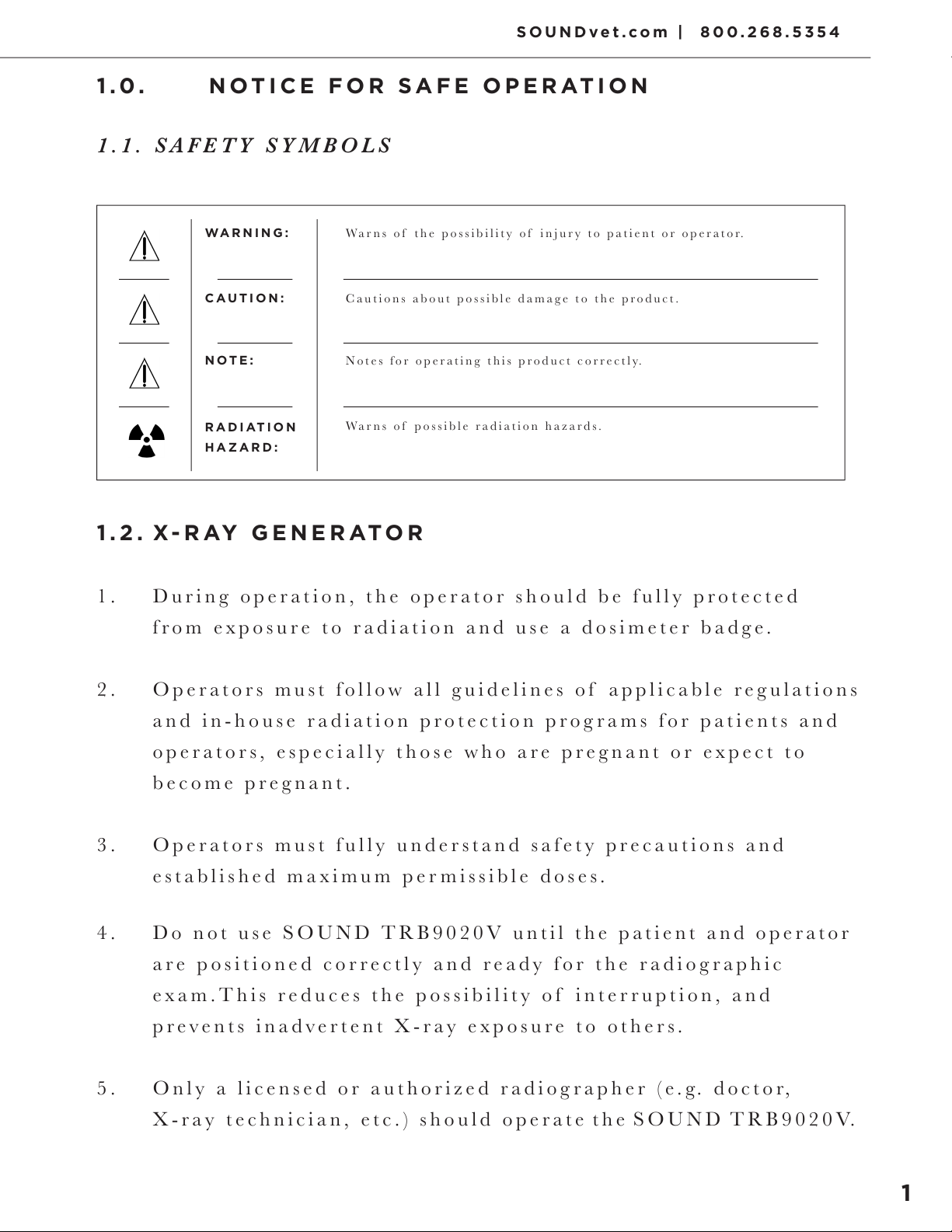
Warns of possible radiation hazards.
Notes for operating this product correctly.
Cautions about possible damage to the product.
Warns of the possibility of injury to patient or operator.
RADIATION
HAZARD:
NOTE:
CAUTION:
WARNING:
1.2. X-RAY GENERATOR
4. Do not use SOUND TRB9020V until the patient and operator
are positioned correctly and ready for the radiographic
exam.This reduces the possibility of interruption, and
prevents inadvertent X-ray exposure to others.
5. Only a licensed or authorized radiographer (e.g. doctor,
X-ray technician, etc.) should operate the SOUND TRB9020V.
1
7. During operation, consult and/or develop a technique chart
for appropriate anatomy, distance, and screen/film or digital
imaging system speed.
6. Please take the following precautions during insallation:
This X-ray unit may be dangerous to patient and operator unless safe exposure
factors and operating instructions and maintenance schedules are observed.
A) Keep equipment dry.
B) Do not subject equipment to excessive atmospheric
pressure, temperature, humidity, direct sunlight, dust,
or air containing salt and sulphur.
C) Do not subject equipment to excessive vibration and/
or shock during transportation, etc.
D) Do not store equipment under any adverse gaseous
conditions.
E) Insure that the input electrical voltage, amperage and
hertz are correct and the charger is properly grounded.
2

This X-ray unit may be dangerous to patient and operator unless safe exposure
factors and operating instructions and maintenance schedules are observed.
8. After using the equipment:
A) Remove cords carefully, if necessary.
B) Keep equipment clean and dry.
C) Store inside carrying case in cool, dry environment.
9. Maintenance.
For proper maintenance, this schedule must be followed:
A) Every 6 months
B) Battery should be fully charged. If the battery is not
fully charged over 6 months, battery cells will over-
discharge and become damaged.
(Charging to 50% at every 2 months is recommended.)
C) Check the alignment of the collimator light field with
the x-ray beam.
D) Check the audible and visible exposure functions.
E) Check to see that all bolts, screws and lock nuts
are tight.
G) Re-adjust the position of laser beams to be aligned with
the central ray of the x-ray unit at the source-to im
age-distance (SID) you typically use.
3
SOUNDvet.com | 800.268.5354
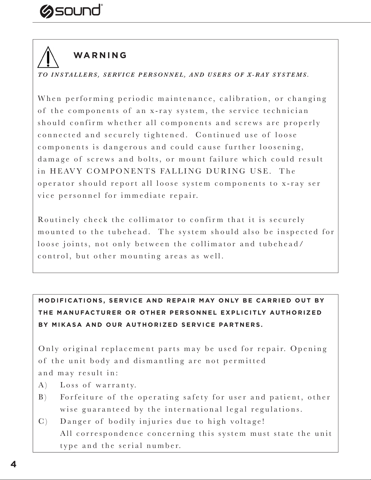
TO INSTALLERS, SERVICE PERSONNEL, AND USERS OF X-RAY SYSTEMS.
When performing periodic maintenance, calibration, or changing
of the components of an x-ray system, the service technician
should confirm whether all components and screws are properly
connected and securely tightened. Continued use of loose
components is dangerous and could cause further loosening,
damage of screws and bolts, or mount failure which could result
in HEAVY COMPONENTS FALLING DURING USE. The
operator should report all loose system components to x-ray ser
vice personnel for immediate repair.
Routinely check the collimator to confirm that it is securely
mounted to the tubehead. The system should also be inspected for
loose joints, not only between the collimator and tubehead/
control, but other mounting areas as well.
WARNING
MODIFICATIONS, SERVICE AND REPAIR MAY ONLY BE CARRIED OUT BY
THE MANUFACTURER OR OTHER PERSONNEL EXPLICITLY AUTHORIZED
BY MIKASA AND OUR AUTHORIZED SERVICE PARTNERS.
Only original replacement parts may be used for repair. Opening
of the unit body and dismantling are not permitted
and may result in:
A) Loss of warranty.
B) Forfeiture of the operating safety for user and patient, other
wise guaranteed by the international legal regulations.
C) Danger of bodily injuries due to high voltage!
All correspondence concerning this system must state the unit
type and the serial number.
4

THE SOUND TRB9020V IS A BATTERY POWERED X-RAY
DEVICE UTILIZING THE LATEST HIGH FREQUENCY
RESONANT INVERTER SYSTEM. THIS X-RAY UNIT HAS
THE FOLLOWING FEATURES:
1. This x-ray unit is very easy to carry by hand because of its small
size and low weight.
2. This unit is battery powered.
3. Dual Laser Pointers in the light beam collimator are easy to adjust
to indicate the central ray at your typical
source-to-image distance (SID).
4. A high frequency resonant inverter with output greater than con
ventional models and constant x-ray tube voltage.
5. Output of kV and mA are corrected and stabilized by automatic
feedback circuits.
6. Focal spot size is 0.8 mm only. Therefore, the quality of X-ray
images is almost the same or better than X-ray images taken by
bigger stationary X-ray units.
7. The kV can be adjusted in 2kV steps from 40 kV to 90 kV. mA
output adjusts automatically. kV, mAs and sec. are digitally
indicated on the Control Panel.
8. It is easy to select either exposure time or mAs display on the
Control Panel.
9. X-ray exposures are confirmed by buzzer and X-ray Indicator.
10. The last kV and timer settings before the unit is turned off are
stored for the next operation.
11. Five different technique settings may be stored in memory for
quick recall on this x-ray unit.
12. The SOUND TRB9020V has an interface connector for DR digital
imaging system.
5
2.0. INTRODUCTION
SOUNDvet.com | 800.268.5354
As the SOUND TRB9020V uses high voltage, please read this manual
carefully prior to operation.
1. X-ray Unit (SOUND TRB9020V ) 1 set
2. Hand-held Exposure Switch and Cord 1 pc
3. Instruction manual 1 pc
4. Battery 1 pc
5. Battery Charger 1 pc
6. AC Adapter 1 pc
7. AC Adapter Power Cord 1pc
WARNING
3.0. COMPONENTS
6
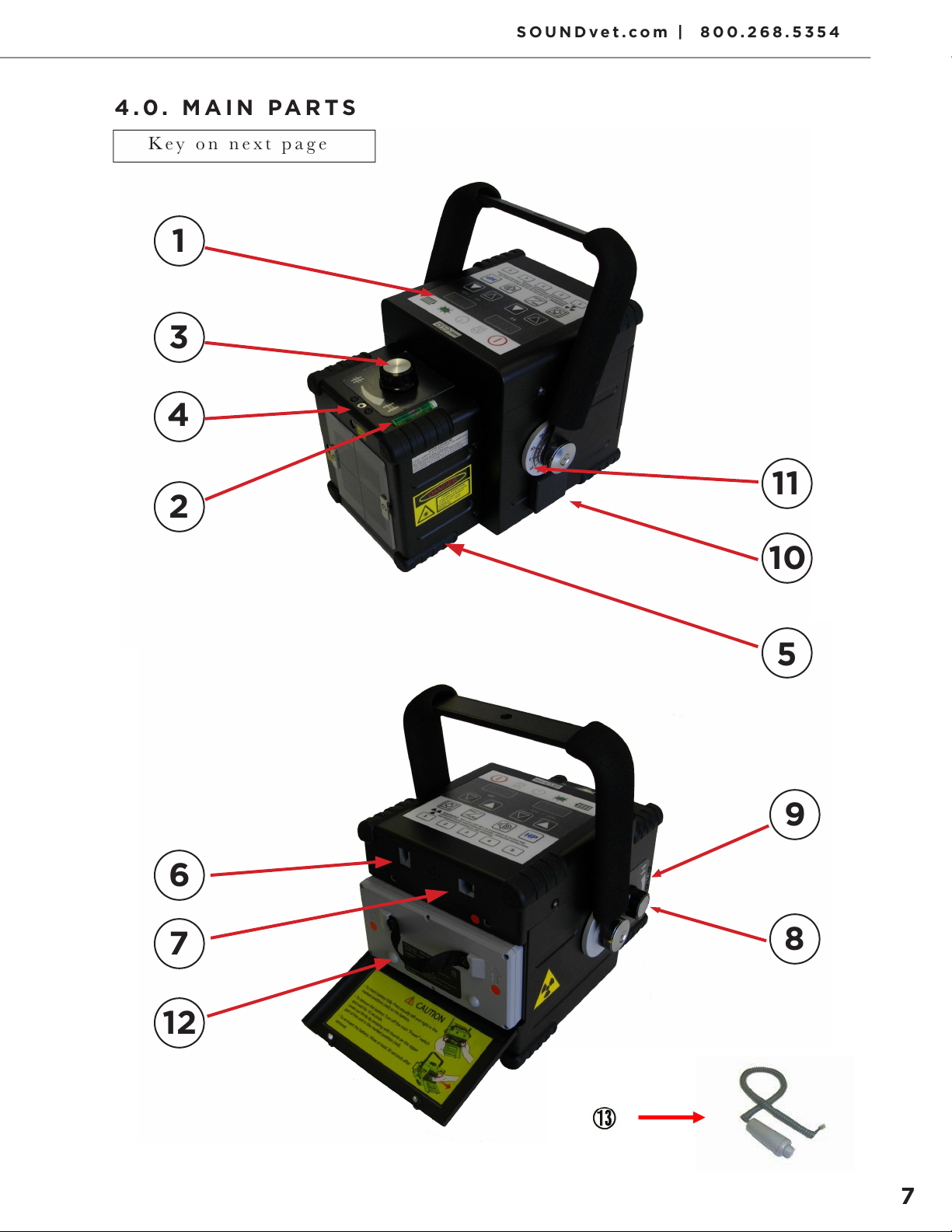
Key on next page
4.0. MAIN PARTS
7
SOUNDvet.com | 800.268.5354
1
6
7
12
9
8
2
3
4
11
10
5

NO. NAME
1. Control Panel
2. Spirit Level
3. Dial to Adjust X-Ray Field Size (Horizontal)
4. Adjustment Screw for Vertical Laser Pointer
5. Collimator
6. Connector for Exposure Switch
7. Connector for DR System
8. Dial to Adjust X-Ray Field Size (Vertical)
9. Adjustment Screw for Horizontal Laser Pointer
10. Tape Measure
11. Angle Indicator
12. Battery
13. Exposure Switch
8
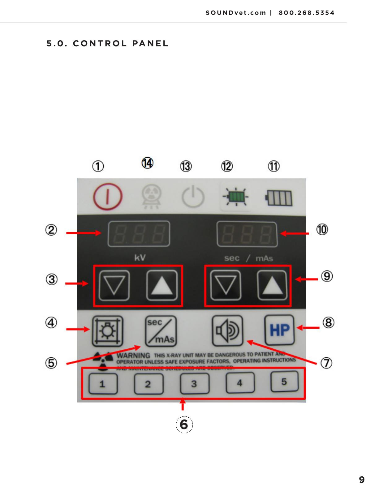
5.0. CONTROL PANEL
6
9
SOUNDvet.com | 800.268.5354

NO. NAME
1. Main Power Switch
2. kV Indicator
3. kV Adjustment Buttons
4. Collimator Light Switch
5. sec / mAs Change Switch
6. Memory Storage Buttons
7. Buzzer ON / OFF Switch
8. High Power Mode Switch
9. sec / mAs Adjustment Buttons
10. Exposure time sec/mAs Indicator
11. Battery Level Indicator
12. Battery Level Indicator Button
13. Ready Indicator
14. X-Ray Indicator
10
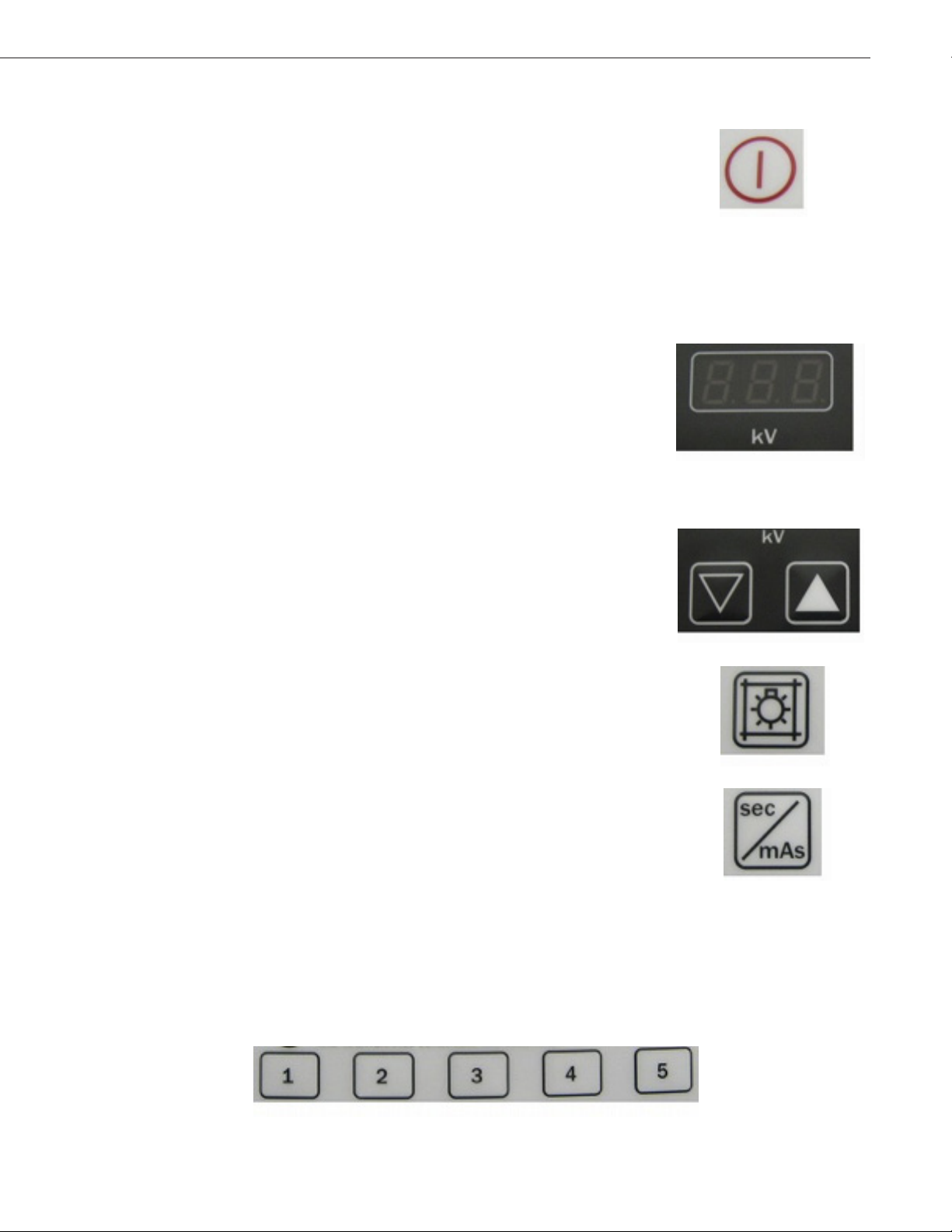
1. Main Power Switch
This button is for turning on and off the
X - r a y g e n e r a t o r.
Pressing the button for a few seconds
(until the unit is power-on).
Press again to power off.
2. kV Indicator
This Indicator displays the tube voltage.
When powered on, it will temporarily display
the version number of the system software
for 4 sec Thereafter it will display the
previous stored kV values. The eco-mode
takesover if the control panel is not operated
for 10 sec. This screen will fade to save power
After another 80 sec., the unit turns itself
off. When powered on again, the previous
settings are displayed
3. kV Adjustment Buttons
These buttons adjust the tube voltage
in 2 kV steps.
4. Light Switch
This button turns on the collimator light. The
dual laser pointers also light up. They
remain on for 30 sec. and automatically turn
off. When the collimator light is on, this
button can be used to turn it off.
5. sec / mAs Toggle Switch
This button toggles the display between
sec and mAs.
6. Memory Storage Buttons (Memory 1 - Memory 5)
Refer to the “8.3 Use of the Memory Storage
Features”
5.1. FEATURES
11
SOUNDvet.com | 800.268.5354
7. Buzzer ON / OFF Switch
This button is for turning on and off the buzzer,
which sounds during X-ray irradiation. If the
buzzer sounds when you press the button, it
means that the buzzer is on.
(This function is not available on this model.)
8. This button turns on and off the High Power
Mode. When you press the button, the kV
indicator and sec / mAs indicator blinks slowly.
The kV indicator will display 90 and sec/mAs
indicator 0.3. The range of High Power Mode is
82 – 90 kV, 0.01 – 0.3 sec.
mA output increases from 10 to 15 in this kV
range. When either of these values is adjusted to
exceed this range, the mode returns to normal.
(The slow blinking will subside.)
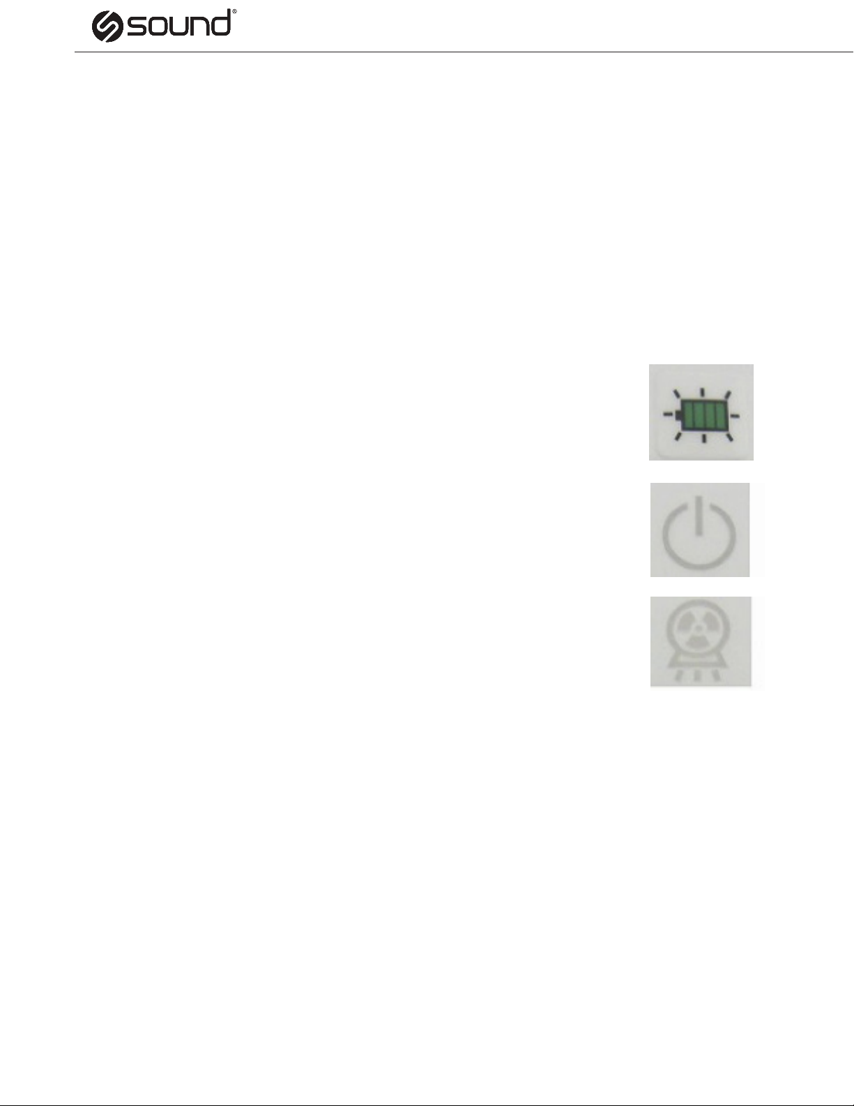
9. sec / mAs Adjustment Buttons
These buttons adjust X-ray irradiation time per
0.01 sec step or mAs value.
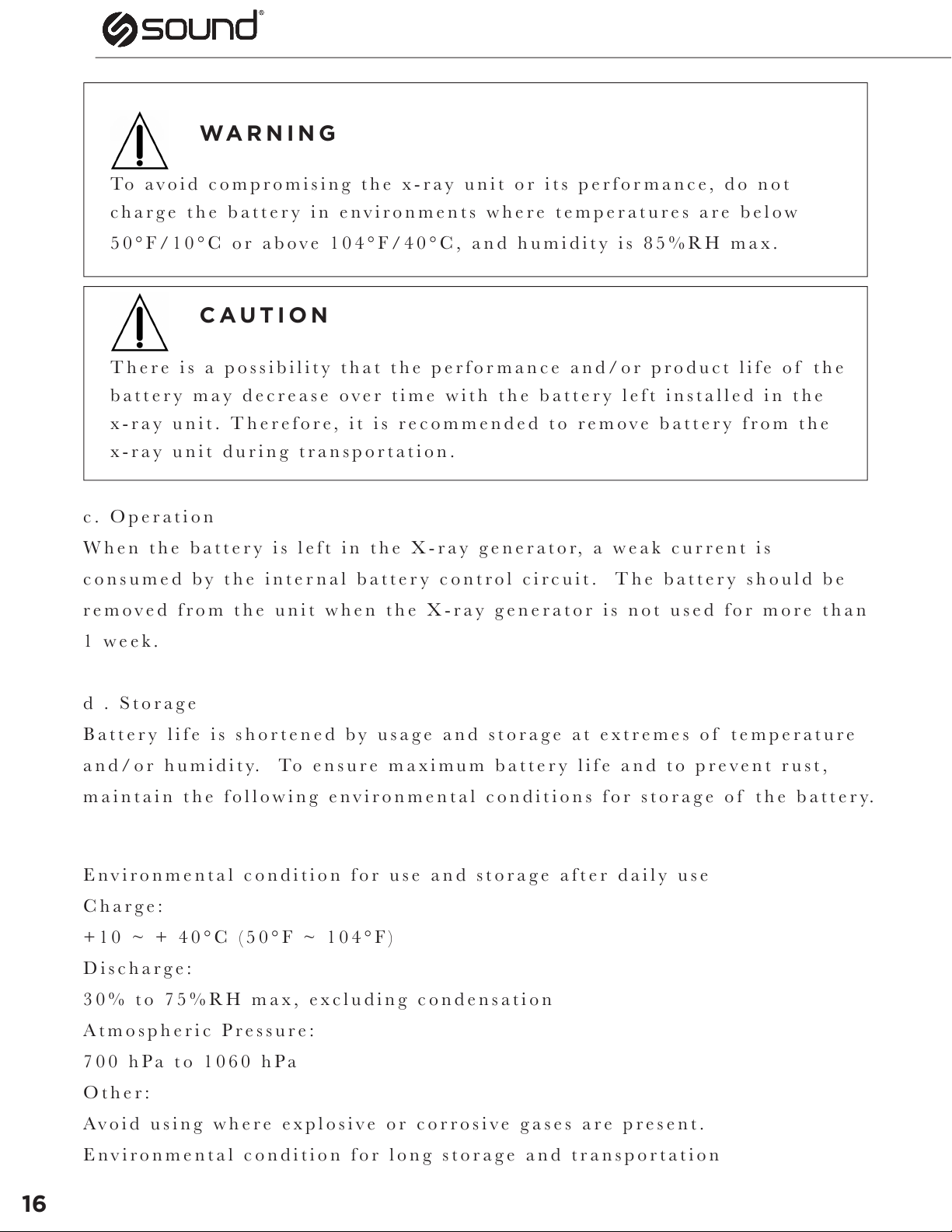
10. sec / mAs Indicator
This indicator displays exposure time or mAs
value. This display will behave in the same way
as the kV indicator i.e. eco-mode after 10 sec
and power off after another 80 sec.
11. Battery Level Indicator
This indicator displays the battery level. It
is shown when the battery level indicator button
is pressed. It is also displayed when you press
the exposure switch.
The indicator lights up as follows
12
* Always recharge the battery when 1 step of green is indicated.
When battery level indicator is RED and kV display shows P11,
exposures are not possible. Remove the battery from the SOUND
TRB9020V and recharge it.
13
SOUNDvet.com | 800.268.5354
12. Battery Level Indicator Button
This switch is for displaying battery indicator.
13. Ready Indicator
This indicator lights up green, when the system
is ready for exposure. See Operation Procedures
for further details.
14. X-Ray Indicator
This indicator is illuminated during
X-ray exposure.
14

a. Maintenance and Care of Battery
The SOUND TRB9020V model features a purpose-built Lithium-Ion
battery designed especially for use with this X-ray unit. It is unique in
the compactness of its size and the power it can generate to provide the
optimum X-ray strength.
Like all rechargeable Lithium-Ion batteries, it requires routine
maintenance and care in its use and handling to achieve maximum battery
life span. The following details the best practice when working with this
product.
Lithium-Ion rechargeable batteries have a limited life and will gradually
lose their capacity to hold a charge. The general estimated life of this
Lithium-Ion rechargeable battery is about 600 charges. (One charge
cycle is a period of use from fully charged, to fully discharged, and fully
recharged again.)
Battery life depends on usage frequency, environment and storage
conditions.
Observing our recommendations for charging operation, storage and
handling of the battery will ensure the maximum lifespan of each battery.
b. Charging
Our instructions and precautions about charging the battery are designed
to ensure the maximum possible life of the battery. If these instructions
are not followed correctly, the battery will still work however its lifespan
may be compromised.
Regarding how to charge, please see the “6.3 Charging the Battery”.
6.0. BATTERY
6.1. BATTERY BEST PRACTICE
15
SOUNDvet.com | 800.268.5354
WARNING
CAUTION
To avoid compromising the x-ray unit or its performance, do not
charge the battery in environments where temperatures are below
50°F/10°C or above 104°F/40°C, and humidity is 85%RH max.
There is a possibility that the performance and/or product life of the
battery may decrease over time with the battery left installed in the
x-ray unit. Therefore, it is recommended to remove battery from the
x-ray unit during transportation.
c. Operation
When the battery is left in the X-ray generator, a weak current is
consumed by the internal battery control circuit. The battery should be
removed from the unit when the X-ray generator is not used for more than
1 w e e k .
d . Storage
Battery life is shortened by usage and storage at extremes of temperature
and/or humidity. To ensure maximum battery life and to prevent rust,
maintain the following environmental conditions for storage of the battery.
Environmental condition for use and storage after daily use
Charge:
+10 ~ + 40°C (50°F ~ 104°F)
Discharge:
30% to 75%RH max, excluding condensation
Atmospheric Pressure:
700 hPa to 1060 hPa
Other:
Avoid using where explosive or corrosive gases are present.
Environmental condition for long storage and transportation
16
Table of contents
Other SOUND Medical Equipment manuals

Popular Medical Equipment manuals by other brands


Getinge
Getinge Arjohuntleigh Nimbus 3 Professional Instructions for use

Mettler Electronics
Mettler Electronics Sonicator 730 Maintenance manual

Pressalit Care
Pressalit Care R1100 Mounting instruction

Denas MS
Denas MS DENAS-T operating manual

bort medical
bort medical ActiveColor quick guide

AccuVein
AccuVein AV400 user manual


