FPS
A-48
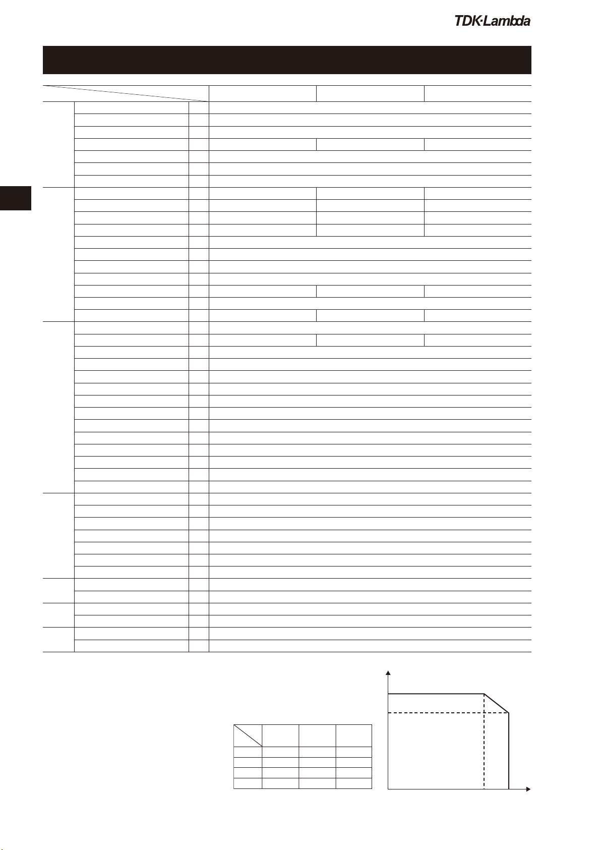
Fig.1Ratedoutputcurrentvsratedoutputvoltage
V2
Vout(V)
V1
l1 l2
FPS1000
-24
V1
V1
Model
24V
V2 29V
l1 33A
l2 40A
FPS1000
-12
12V
13.2V
66A
72A
48V
58V
17.25A
21A
FPS1000
-48
Iout(A)
・All specifications are subject to change without notice.
ITEMS/UNITSMODEL FPS1000-12 FPS1000-24 FPS1000-48
Input
Voltage Range (*1) V AC85 - 265 continuous (Universal input)
Frequency (*1) Hz 47 - 63, single phase
Power Factor (115/230VAC)(typ)
More than 0.98 at maximum output power
Efficiency (typ) (*2) %81 / 83 84 / 86 85 / 88
Current (100/200VAC) (max) A 12.0 / 6.0
Inrush Current (*3) A Less than 40
Leakage Current (230VAC) mA Less than 1.1
Output
Nominal Voltage
VDC
12 24 48
Maximum Current (*Fig.1) A 72 40 21
Maximum Power W 864 960 1008
Voltage Set Point 12V +/-1% 24V +/-1% 48V +/-1%
Maximum Line Regulation(*5)
0.40%
Maximum Load Regulation(*6)
0.80%
Temperature Coefficient 200PPM/℃
Warm Up Drift
0.1% of rated Vout for 8hrs after 30min warm-up. Constant line, load and temperature.
Maximum Ripple & Noise (*4)
mVp-p
150 200 300
Hold-up Time (100VAC)(typ) ms 20 at rated output voltage and less than 80% of rated load.
Voltage Adjustable Range
VDC
10.5 - 13.2 21.5 - 29 43 - 58
Function
Over Current Protection(*Fig.1)
105 - 125% of maximum output current.
Over Voltage Protection (*8)
VDC
14.3 - 15.7 31 - 34 62 - 66
Over Temperature Protection Inverter shut down method, automatic reset.
Remote Sensing (*7) Possible. Refer to instruction manual.
Remote ON/OFF Control By electrical signal or dry contact. ON: 0 - 0.6V or short. OFF: 2 - 15V or open.
Parallel Operation (*9) Possible. Refer to instruction manual.
Series Operation (*10) Possible. Refer to instruction manual.
Over Temperature Alarm Signal
Open collector signal. Normal: ON, Max.sink current: 10mA.
DC OK signal Open collector signal. On when Vout>80+/-5% rated output. Max.sink current: 10mA
AC Fail Signal Open collector signal. On when Vin > 85VAC, Max.sink current: 10mA.
AUX-BIAS Power Supply 11.2 - 12.5VDC. 0.25A maximum output current.
Output Voltage Trimming Possible, via Vout trim pin in the I/O connector. Refer to instruction manual.
Front Panel Indicators AC OK, DC OK, DC FAIL
I²C Interface Optional. Refer to instruction manual.
Environment
Operating Temperature ℃0 to 50: 100% load. Derate 2%/℃, 50 to 60
Storage Temperature ℃-30 to 85
Operating Humidity
%RH
10 - 90, no condensation.
Storage Humidity
%RH
10 - 95, no condensation.
Vibration Built to meet ETS 300 019
Shock Built to meet ETS 300 019
Cooling By internal fans. Variable speed control.
Isolation
Withstand Voltage
Input-Output: 3000Vrms, 1min. Input-Ground: 2000Vrms, 1min. Output-Ground: 500Vrms, 1min.
Isolation Resistance More than 100Mohm at 25℃and 70% RH. Output-Ground: 500VDC
Standards
Safety Standards Approved by UL60950-1, EN60950-1, CSA C22.2 No.60950-1
EMI (*11) EN55022B, FCC part 15J-B, VCCI-B
Mechanical
Weight (typ) g 2000
Size (W x H x D) mm 127 x 41 x 290 (Refer to outline drawing.)
(*1) For cases where conformance to various safety standards (UL, EN etc.)
is required, to be described as 100-240Vac (50/60Hz).
(*2) At 100/200VAC, rated load and 25℃ambient temperature.
(*3) Not applicable for the noise filter inrush current less than 0.2ms.
(*4) Measured with JEITA RC-9131 1:1 probe, 20MHz B.W.
(*5) From 85-132Vac or 170-265VAC, constant load.
(*6) From no-load to rated load, constant input voltage.
Measured at the sensing point in remote sense.
(*7) Remote sensing can compensate up to 1V drop on
each load wire.
(*8) Inverter shut down method. Reset by AC voltage
recycle or by ON/OFF control.
(*9) Derate maximum output power by 10% for input
voltage less than 100V
RMS
.
(*10) Series operation is not applicable for units
with I
2
C bus option (/S, /PS model).
(*11) For FPS 1000-12/P(S), when used not with FPS-S1U or FPS-T1U
racks, an EMI suppressor clamp should be attached to the AC cable,
as close as possible to the AC inlet, to meet class B.
FPS1000 Specifications
FPS1000


