CDI 113-4985 Guide

Installation and Troubleshooting Guide
This installation is to be completed by an Authorized Dealer or Professional Service
Technician. For questions regarding installation or warranty, call CDI Tech Support
at 866-423-4832. Do not return to the Dealer or Distributor where the part was purchased.
Contact CDI Electronics Directly for Return Material Authorization.
CDI Electronics •353 James Record Road SW •Huntsville, AL 35824 USA
Web Support: www.cdielectronics.com •Tech Support: 1-866-423-4832 •Order Parts: 1-800-467-3371
All rights reserved. Reproduction or use of content, in any manner, without express written permission by CDI Electronics, Ilc., is prohibited.
Rev H •8/3/2021 Page - 1 of 4QF-358
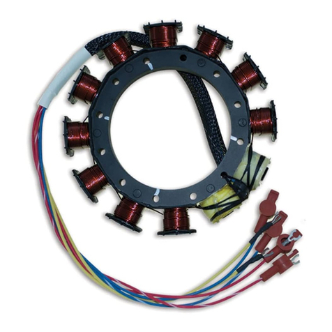
CDI P/N: 113-4985
This unit replaces the following P/N's: 584910, 584985, 584990, and 765387.
Warning! This product is designed to be installed by a professional marine mechanic. CDI Electronics cannot be held liable
for injury or damage resulting from improper installation, abuse, neglect, or misuse of this product.
DO NOT OPERATE ENGINE WITH PLASTIC ENCODER COVER OFF OF THE ENGINE.
Do not operate with a black sleeved Stator from a 1991-92 model engine.
This unit requires special inductive spark plug wires and spark plugs. Please use the Factory Recommended Champion
QL78YC (0.030 Gap) Spark Plugs and the inductive Gray or Blue spark plug wires (Order CDI P/N: 931-4921 for a set of 6
wires).
How to test the Engine Stop Circuit (Kill) for DC Voltage:
1. DC voltage present on the kill circuit of the Power Pack due to a faulty key switch, boat harness, or engine harness will severely
damage the Power Pack’s internal kill circuit. Connect a Digital Multi Meter to the Ignition Stop wire AT THE POWER PACK while
disconnected from the Power Pack in reference to a known good engine ground. Turn the Ignition switch on and off several times.
If, at any time, you see over 2 VDC on the kill wire, there is a problem with one or both harnesses and/or the Ignition switch. The
Ignition Stop wire should not be connected back to the new Power Pack at any point until the problem is corrected OR DAMAGE
TO THE POWER PACK WILL OCCUR!
INSTALLATION
1. Disconnect the negative battery cable.
2. Remove Encoder wheel cover, Power Pack cover, and Voltage Regulator cover (Between the timing cover and the Power Pack).
3. Disconnect the Stator wire connector from the Power Pack.
4. Disconnect the harness wire connector from the Power Pack.
5. Disconnect the Optical sensor wire connector from the Optical sensor.
6. Disconnect the spark plug wires from the spark plugs.
7. Unbolt and remove the Ignition coils and old Power Pack. Look for burned areas between the coil mounting holes on the stainless
RF shield. If a discoloration is found, replace that particular Ignition coil. Take care not to over-torque the mounting bolts, OEM
specification calls for 50-95 in lbs. of torque.
8. Disconnect the primary wires of the old Power Pack from the Ignition coils and connect the primary wires of the new Power Pack to
the Ignition coils. The Orange/Blue primary wires are for cylinders 1 and 2, the solid Orange Primary wires are for cylinders 3 and
4, and the Orange/Green primary wires are for cylinders 5 and 6.
9. Make sure the RF noise shield is between the Ignition coils and the Power Pack.
10. Connect the Stator and harness connectors to the Power Pack. Use a small amount of dielectric silicone grease on the connector
seal but do not put any inside the sockets.
11. Connect the harness wire connector to the Power Pack.
12. Connect the Optical sensor connector to the Optical Sensor.
13. Replace the timing wheel cover, Power Pack cover, and Voltage Regulator cover.
14. Connect the spark plug wires to the spark plugs.
15. Reconnect the negative battery cable.
IF AN OPTICAL SENSOR TESTER/IGNITION ANALYZER IS NOT AVAILABLE:
1. Connect all spark plug wires to a spark gap tester.
2. Disconnect the Port temperature switch’s Tan and White/Black wires.
3. Connect a jumper wire to the Tan wire and short it to engine ground.
4. Connect a timing light to the # 1 spark plug wire.
5. Connect the battery cables.
6. Disconnect the engine harness from the boat harness.
7. Using a piston stop tool or dial indicator, verify the TDC timing pointer’s accuracy. Reset as needed to correct.
8. Use a remote starter and a Timing light, verify the ignition timing out of Quick Start as follows:
Engine Idle timing WOT timing
150-175 HP 4-6° ATDC 20° BTDC
NOTE: Adjust the idle timing to adjust the engine idle speed.

Installation and Troubleshooting Guide
This installation is to be completed by an Authorized Dealer or Professional Service
Technician. For questions regarding installation or warranty, call CDI Tech Support
at 866-423-4832. Do not return to the Dealer or Distributor where the part was purchased.
Contact CDI Electronics Directly for Return Material Authorization.
CDI Electronics •353 James Record Road SW •Huntsville, AL 35824 USA
Web Support: www.cdielectronics.com •Tech Support: 1-866-423-4832 •Order Parts: 1-800-467-3371
All rights reserved. Reproduction or use of content, in any manner, without express written permission by CDI Electronics, Ilc., is prohibited.
Rev H •8/3/2021 Page - 2 of 4QF-358
TROUBLESHOOTING
NO SPARK ON ANY CYLINDER:
1. Disconnect the port 4 pin connector on the Power Pack that holds the Black/Yellow stop wire and retest. If the engine's ignition now
has spark, the stop circuit has a fault. Check the key switch, harness, and shift switch.
2. Disconnect the Yellow wires from the Stator to the Voltage Regulator and retest. If the engine sparks, replace the Voltage
Regulator.
3. Check the cranking RPM. A cranking speed of less than 250 RPM will not allow the system to spark properly. This can be caused
by a weak battery, dragging starter, bad battery cables, or a mechanical problem inside the engine.
4. Check the Stator resistance and DVA as given below:
Read from Read to Ohms DVA (Connected) DVA (Disconnected)
Brown (Stator) Brown/Yellow (Stator) 450-600 Ω150-400 V 150-400 V
Brown/White (Stator) Brown/Black (Stator) 450-600 Ω150-400 V 150-400 V
Orange (Power coil) Orange/Black (Power coil) 50-60 Ω11-22 V 45-120 V
5. Check the DVA on the Black/Yellow kill wire by back probing the connector of the Power Pack. You should have a reading of at
least 150 DVA or more. The Stator and Optical Sensor plugs should be connected to the Power Pack for this test. If you do not,
check the DVA on the Stator and the DC voltage on the Optical Sensor. If the DVA on the Stator and the DC voltage is good on the
Optical Sensor but the DVA on the Black/Yellow Kill wire coming out of the Power Pack is low, the Power Pack is likely faulty.
6. Verify the engine is turning in a clockwise direction. If not, see TRIES TO RUN BACKWARDS.
7. Check the Power Pack and Ignition coil ground wires for corrosion and tightness.
8. If the engine loses spark after the key switch is disengaged, check the DVA on the Stator’s Power Coil. If the DVA is low, the Stator
is likely defective.
9. Check the battery voltage on the Yellow/Red wire while cranking the engine. If below 11 VDC, charge the battery and check all
battery cables. A continued low battery reading could be caused by a dragging starter, a faulty starter solenoid, or a faulty key
switch.
10. Remove the Optical sensor wheel and check for damage, especially where the top slots are located. Sometimes the wheels will
break out where the windows overlap.
The thin area between the crank position and the cylinder position is the most common breakout location.
11. Check the Optical sensor eyes for dirt, grease, etc. If you have to clean it, use denatured alcohol and a Q-tip. Do not use any other
cleaning agent because damage to the Optical lens will occur.
12. Check the Power Pack DVA to the Primary coil wires as follows:
Read from Read to DVA (Connected)
Orange/Blue Engine Gnd 150 V Minimum
Orange Engine Gnd 150 V Minimum
Orange/Green Engine Gnd 150 V Minimum
NOTE: If the Orange Primary DVA reading is low on one cylinder, disconnect the wire from the Ignition coil for that
cylinder and reconnect it to a Pack Load resistor (CDI P/N 511-9775). Retest. If the reading is now within specification, the
Ignition coil is likely defective. If it still measures low, this indicates a defective Power Pack If the Optical sensor tests
within specification.
13. Check the Optical sensor DC voltage as follows:
Read from Read to OEM DC (Connected) CDI DC (Connected)
Orange/Red (Input from Power Pack) Engine Gnd 11 V Minimum 9.5 V Minimum
Black/Orange (Return from Optical sensor) Engine Gnd 9 V Minimum 7.5 V Minimum
WARNING! The Black/Orange wire should NEVER be shorted to engine ground as this will damage the sensor.
NOTE: When checking the Optical sensor, there can be only a maximum voltage difference of 2 V DC between the input
voltage and the return voltage. If the voltage difference is more than 2 V, or if the input voltage and the return voltage are
equal (given that the input voltage is at an acceptable reading), replace the Optical sensor.

Installation and Troubleshooting Guide
This installation is to be completed by an Authorized Dealer or Professional Service
Technician. For questions regarding installation or warranty, call CDI Tech Support
at 866-423-4832. Do not return to the Dealer or Distributor where the part was purchased.
Contact CDI Electronics Directly for Return Material Authorization.
CDI Electronics •353 James Record Road SW •Huntsville, AL 35824 USA
Web Support: www.cdielectronics.com •Tech Support: 1-866-423-4832 •Order Parts: 1-800-467-3371
All rights reserved. Reproduction or use of content, in any manner, without express written permission by CDI Electronics, Ilc., is prohibited.
Rev H •8/3/2021 Page - 3 of 4QF-358
14. Check the Charge coil flywheel magnets for cracked, broken, or loose magnets.
ONLY HAS SPARK AS LONG AS THE KEY SWITCH IS ENGAGED OR WILL NOT REV ABOVE IDLE SPEED:
1. Check the DVA on the Stator’s Power coil.
2. As the engine RPM increases, the DVA should rapidly increase and stabilize up to 22 DVA (voltage exceeding 22 DVA indicates a
bad Power Pack). A sharp drop in voltage right before the miss becomes apparent usually indicates a bad Stator Charge coil
winding. A sharp drop in voltage when you disengage the key switch indicates a bad Power coil on the Stator.
ENGINE TRIES TO RUN BACKWARDS:
1. Check the encoder wheel. It must have 7 notches.
2. Check the ignition timing. Before Quick Start, it should be set to 2-6° BTDC. After Quick Start, it should be set to 4-6° ATDC.
3. If possible, try another Optical sensor.
4. If still no change, replace the Power Pack.
NO FIRE OR INTERMITTENT FIRE ON ONE BANK:
1. Check the Stator resistance and DVA (see NO FIRE ON ANY CYLINDER).
2. Disconnect the 4-pin connector on the port side of the Power Pack and see if the fire returns. If it does, check resistance to see if
the Black/Yellow wire is shorted to engine ground or is intermittently shorting to ground.
NO FIRE ON ONE CYLINDER:
1. Check the DVA on the Orange primary wire going to the Ignition coil not firing. You should have a reading of 150 DVA or more.
2. Check the resistance of the Ignition coil secondary circuit in reference to engine ground. A difference of over 25 Ωindicates a
defective Ignition coil.
3. Check the resistance of the spark plug wire. Normally, you will read approximately 100 Ωbetween the connectors on either end.
POWER PACK REPEATEDLY BLOWS ON SAME CYLINDER:
1. Replace the Ignition coil on the cylinder dropping spark.
ENGINE WILL NOT STOP (KILL):
1. Disconnect the stop wire at the Power Pack. Connect a jumper wire to the stop terminal in the Power Pack and short it to engine
ground. If this stops the Power Pack from sparking, the stop circuit has a fault. Check the key switch, harness, and shift switch.
ONLY FIRES #1 CYLINDER:
1. Verify the engine is spinning in a clockwise direction.
2. Check the Optical sensor to encoder wheel alignment. You may need to shim the Optical sensor upwards 0.020” to 0.0285” to
make it engage the encoder wheel.
HIGH SPEED MIS-FIRE OR WEAK HOLE SHOT:
1. Connect DVA meter to between the Brown wires and do a running test. At no time should the voltage exceed 400 DVA. If it does,
the Regulator circuit in the Power Pack is bad. The voltage should show a smooth climb and stabilize, gradually falling off above
5000 RPM. If you see a sudden drop in voltage right before the miss becomes apparent, the problem is likely in the Stator.
2. Disconnect the Yellow wires from the Stator to the Voltage Regulator and retest. If the miss clears, replace the Voltage Regulator.
3. Check the DVA on the Orange primary wires from the Power Pack while connected to the Ignition coils. You should have a reading
of at least 150 DVA or more, increasing with engine RPM until it reaches 300-400 DVA maximum. A sharp drop in DVA right before
the miss becomes apparent on all cylinders will normally be caused by a bad Stator. A sharp drop in DVA on less than all cylinders
will normally be the Power Pack.
4. Connect an inductive tachometer to the spark plug wires one at a time and compare the readings. If most of the cylinders show the
same reading and one or two show different readings, check the primary wires with the inductive pickup to see if the readings are
the same from the Power Pack. A difference in readings between the primary and secondary coil wires usually indicates a bad coil
or bad ignition wires. No difference indicates a bad Power Pack.
5. Perform a high speed shutdown and read the spark plugs. Check for a black porcelain insulator or one that looks brand new. A
crack in the block can cause a miss at high speed when the water pressure gets high and sprays water into the cylinder, but a
normal shutdown will mask the problem.
6. Check the Charge coil flywheel magnets for cracked, broken, or loose magnets.

Installation and Troubleshooting Guide
This installation is to be completed by an Authorized Dealer or Professional Service
Technician. For questions regarding installation or warranty, call CDI Tech Support
at 866-423-4832. Do not return to the Dealer or Distributor where the part was purchased.
Contact CDI Electronics Directly for Return Material Authorization.
CDI Electronics •353 James Record Road SW •Huntsville, AL 35824 USA
Web Support: www.cdielectronics.com •Tech Support: 1-866-423-4832 •Order Parts: 1-800-467-3371
All rights reserved. Reproduction or use of content, in any manner, without express written permission by CDI Electronics, Ilc., is prohibited.
Rev H •8/3/2021 Page - 4 of 4QF-358
ENGINE WILL NOT ACCELERATE BEYOND 2500 RPM (Runs smooth below that RPM):
1. Verify the engine is not actually over heating by using a digital pyrometer.
2. Check the routing of the Tan temperature wires, an example of a bad location is shown below. The Tan wires have to be located as
far away as possible from the spark plug wires.
Unacceptable routing for the temp wire (V6 engine shown).
3. Verify the engine is not overheating and disconnect the Tan temperature sensor wire. If the engine performs normally, check both
temperature sensors and replace the defective one.
4. If there is not any indication of a problem at this point, replace the Power Pack.
ENGINE STAYS IN QUICK-START:
1. Check the Yellow/Red wire for DC voltage while the engine is running. You should only see voltage on this wire while the starter
solenoid is engaged. A voltage reading of 5-7 VDC will not engage the starter solenoid but will engage Quick Start. Check the
starter solenoid, harness, and ignition switch.
2. Short the White/Black temperature switch wire from the Power Pack to engine ground. Start the engine, if the Quick Start drops out
after approximately 5 seconds, replace the White/Black temperature switch.
3. Disconnect the Black/White wire from the Power Pack. If the Quick Start feature is not now working, replace the Power Pack.
ENGINE DIES WHEN QUICK-START DROPS OUT:
1. Check ignition timing at idle with the White/Black temperature wire disconnected. Remember to allow for the drop in ignition timing
when Quick Start disengages. Verify ignition timing after engine has warmed up, according to the service manual.
QUICKSTART DOES NOT WORK:
1. Check DVA from the Orange to the Orange/Black Power coil wires while connected to the Power Pack. The reading should be 8-24
DVA. A reading above 24 V indicates a problem in the Power Pack while a reading below 8 DVA usually indicates a problem in the
Stator.
WILL NOT RUN WHEN HOT:
1. Check the Stator resistance and DVA as given below:
Read from Read to Ohms DVA (Connected) DVA (Disconnected)
Brown (Stator) Brown/ White (or Brown/Yellow) Stator 900-1200 Ω150-400 V 150-400 V
Orange (Power Coil) Orange/Black (Power Coil) 50-60 Ω11-22 V 45-120 V
2. Test the Optical sensor while hot (CDI P/N 511-4017 Optical Sensor Tester) or by using another Optical sensor for testing.
Table of contents
Other CDI Marine Equipment manuals
Popular Marine Equipment manuals by other brands

Simrad
Simrad MS70 installation manual

Ocean Signal
Ocean Signal rescureME MOB1 quick start guide

Orbit
Orbit OceanTRx7 Configuration and Best Practices Technical Notes

Mercury
Mercury Active Trim Quick reference guide

Furuno
Furuno NAVpilot-700 installation instructions

PRM NEWAGE
PRM NEWAGE PRM90 Workshop manual