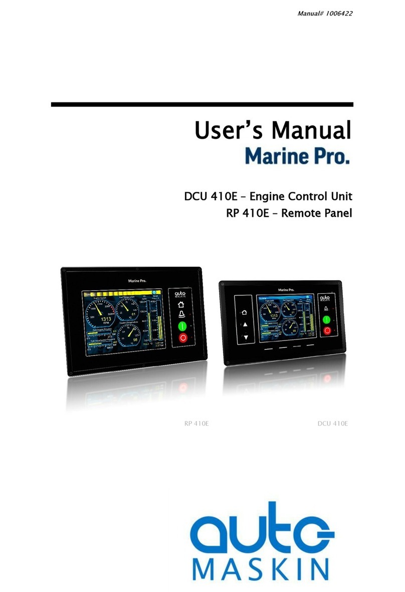
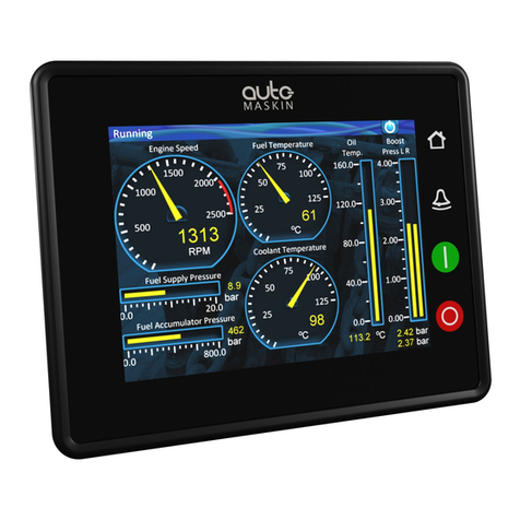
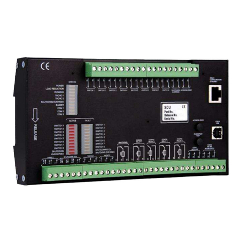
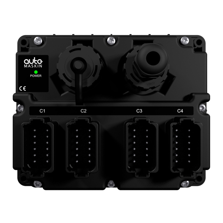
auto maskin Marine Pro 400 Series Instruction sheet

Publication P/N 1006423
Configuration Manual
400 Series / 200 Series
DCU 410E Engine Controller, P/N 1006445
RP 410E Remote Panel, P/N 1006446
DCU 408E Engine Controller, P/N 1006510
RP 210E Remote Panel, P/N 1006476
DCU 210E Engine Controller, P/N 1006475
RP 220E Remote Panel, P/N 1006472
DCU 208E Engine Controller, P/N 1006477
RP 206E Remote Panel, P/N 1006478

Table of content
1 Preface 5
1.1 About this Manual 5
1.2 Responsibilities 5
1.3 Revisions 5
1.4 Trademarks 5
2 Configuration 6
2.1 Configuration & Firmware Files 6
2.1.1 DCU Web Server Configuration
Interface 6
2.1.2 DCU User Interface Menu 6
2.1.3 USB Memory Interface 6
2.1.3.1 Configuration Files 7
2.1.3.2 Firmware Files 8
2.1.3.3 Copy Configuration File or
Event Log 8
2.2 Connecting to the DCU 8
2.2.1 To Connect to the DCU 8
2.2.2 Further Connection Settings 9
2.2.2.1 Change the IP address of
the DCU 9
2.2.2.2 IP Address Convention
9
2.2.2.3 Connect the DCU to a
Single PC 9
2.2.2.4 To Connect the DCU to a
LAN with a DHCP server 9
2.2.2.5 Connection to a LAN using
Fixed IP Addresses 10
2.2.2.6 Factory Defaults for the
DCU 10
2.2.2.7 IP Address Conflict 10
2.3 Web Server Configuration 10
2.3.1 DCU 11
2.3.2 RIO 11
2.3.3 SDU 11
2.3.4 MK-14 11
2.3.5 Upload Wallpaper 11
2.3.6 Versions 11
2.3.7 Troubleshooting 12
3 Main DCU Web Server Menu 12
3.1 Access Control 13
3.1.1 Access Control Levels 13
3.2 File 13
3.2.1 Load any File 13
3.2.1.1 Factory Default 13
3.2.1.2 User Uploaded 13
3.2.2 Delete Configuration File 13
3.2.3 Configuration Printout 13
3.2.4 Save File as 13
3.2.5 Save CANopen EDS-file 14
3.2.6 Upload to DCU 14
3.2.6.1 Firmware Update 14
3.2.6.2 Wallpaper 14
3.2.6.3 Configuration File Upload
14
3.3 I/O Configuration 14
3.4 User Interface 14
3.5 Start/Stop/Prelube 14
3.6 Engine Model 14
3.7 Service Interval 15
3.7.1 View Service Status 15
3.7.2 Configure 15
3.8 Communication 16
3.9 Miscellaneous 16
3.10 Language 17
4 I/O Configuration 17
4.1 Common I/O Configuration 17
4.1.1 Common Configuration for
Switch Channels 18
4.1.2 Common Configuration for
Analog Channels 21
4.2 Flexible I/O 24
4.3 Config Inputs 24
4.3.1 Engine Speed 24
4.3.2 Individual Speed Sensors 27
4.3.3 Engine Load 28
4.3.4 Transmission 28
4.3.4.1 Gear 28
4.3.4.2 Interlock/Indications 30
4.3.4.3 Clutch Slip 30
4.3.4.4 Clutch Temperature 32
Page 2 (99)

4.3.4.5 Clutch Pressure 32
4.3.4.6 Thrustbearing
Temperature 32
4.3.4.7 Shaft Speed 32
4.3.5 Switch 33
4.3.6 4-20 mA 34
4.3.7 PT100 34
4.3.8 Temperature Sensor 35
4.3.9 Voltage sensor 37
4.3.10 24V Input Functions 37
4.3.11 J1939 38
4.3.11.1 Configuration 39
4.3.11.2 Node Signals 39
4.3.12 Differential 39
4.3.13 Average 40
4.3.13.1 Average Signal 40
4.3.13.2 Deviation
Configuration 42
4.3.13.3 Exclude From
Average 43
4.3.13.4 Naming 43
4.3.14 Special 43
4.3.14.1 Input Voltage 43
4.3.14.2 Calculated Fuel Rate 44
4.3.14.3 Calculated Engine Hours
45
4.3.14.4 Instantaneous Fuel
Economy (DCU) 45
4.3.15 Analog Modbus 46
4.3.16 Digital Modbus 46
4.3.17 EGT (Exhaust Gas
Temperature) 47
4.3.17.1 Cylinder Deviation Event
47
4.3.17.2 Turbo Deviation Event 47
4.3.18 Constant 47
4.3.19 Logical Signal 47
4.4 Config Outputs 48
4.4.1 Common Output
Configuration 48
4.4.2 24V Output Functions 51
4.4.3 Relay Functions 51
4.4.4 Speed Relays 52
4.4.5 DM1 Functions 52
4.4.6 J1939 Outputs 53
4.4.6.1 J1939 53
5 User Interface 53
5.1 Configuration 54
5.2 Pages 55
5.3 Flow Charts 58
5.4 RP Home View Configuration 58
5.5 Controls 58
5.6 Shortcuts 60
5.7 Language 61
5.7.1 All Signals 61
5.7.2 Enabled Signals Only 62
5.7.3 Service 62
5.7.4 Built-in Events 62
5.8 Buzzer 63
6 Start/Stop/Prelube 63
6.1 Settings 63
7 Communication 69
7.1 Network Configuration 70
7.2 LSU 408 70
7.3 CANopen 70
7.4 Modbus RTU 70
7.5 Modbus TCP 71
7.6 J1939 Configuration 72
7.6.1 Configuration 72
7.6.1.1 Function Specific
Configuration 73
7.6.1.2 OEM Specific
Configuration 74
7.7 Communication Info 74
8 Miscellaneous 74
8.1 Engine Application Configuration
75
8.2 Event Configuration 76
8.2.1 Miscellaneous Events 76
8.2.2 Suppress DM1 Fault 77
8.2.3 DM1 FMI Severity 77
8.2.4 Output Event Configuration
77
8.2.5 Modbus Watchdogs 78
8.3 Counter Configuration 78
8.4 Counters 79
8.5 Acknowledge Configuration 79
Page 3 (99)

8.6 Operation Mode Configuration 80
8.7 Event Log 80
8.8 Override Configuration 81
8.9 System Voltage Configuration 82
8.10 Sea Trial 82
8.11 Custom Version Text 82
8.12 Factory Reset 82
9 Communication Interface List 82
9.1 DCU Capacity 82
9.1.1 Functionality and Content
Highlights 83
9.1.2 Total I/O capacity 83
10 RIO 410 Configuration 84
11 RP Configuration 84
11.1 Power On Wizard 85
11.2 Administration Menu 86
11.2.1 DCU Connection / Connections
86
11.2.1.1 Manually Assignment
of DCUs 87
11.2.2 DCU Alarms 87
11.2.3 DCU Acknowledge 87
11.2.4 IP Address 88
11.2.5 Cameras 88
11.2.6 Station Location 89
11.2.7 Functional Inputs 89
11.2.8 Functional Outputs 91
11.2.9 Change Password 91
11.2.10 Station Priority 91
11.2.11 Lock 93
11.2.12 Start/Stop Buttons 93
11.2.13 Web Interface 93
11.2.14 Reset to Factory Defaults
93
12 Troubleshooting 93
12.1 Password 93
Page 4 (99)

1 Preface
1.1 About this Manual
This manual has been published primarily for professionals and qualified personnel.
The user of this material is assumed to have basic knowledge in marine systems, and must
be able to carry out related electrical work.
Work on the low-voltage circuit should only be carried out by qualified and
experienced personnel.
Installation or work on the shore power equipment must only be carried out by
electricians authorized to work with such installations.
1.2 Responsibilities
It is the sole responsibility of the installer to ensure that the installation work is
carried out in a satisfactory manner, that it is operationally in good order, that the
approved material and accessories are used and that the installation meets all
applicable rules and regulations.
Auto-Maskin continuously upgrades its products and reserves the right to make
changes and improvements without prior notice.
All information in this manual is based upon information at the time of printing. For updated
information, please contact your local distributor.
1.3 Revisions
This Configuration Manual is valid for the following firmware version of the DCU Engine
Controllers.
Edition
Firmware Version
Release
Release
3.10
March 2020
Configuration Manual revision: March 2020
2 Configuration
This section explains the configuration of the DCU. All configuration except password and
network configuration is stored in a portable configuration file within the DCU.
Page 5 (99)

2.1 Configuration & Firmware Files
The DCU may be configured in one of the following three ways.
1. DCU Web Server Configuration Interface
2. DCU User Interface Manu
3. USB Memory Interface
2.1.1 DCU Web Server Configuration Interface
The DCU has a built-in web server, offering access to full configuration of the DCU.
This is the primary configuration interface.
2.1.2 DCU User Interface Menu
For quick and easy changes to the configuration, there is a configuration entry point in the
menu.
This manual will not describe the panel menu configuration interface in detail. Only
the web server menu operation is covered.
2.1.3 USB Memory Interface
Insert a USB memory stick and follow the guidelines appearing on the DCU screen.
The DCU 408E/208E does not have a screen interface and hence this method
does not work on those units.
Page 6 (99)

2.1.3.1 Configuration Files
If the USB memory stick contains configuration files, they will be listed here.
The configuration filename can only contain the following characters:
● A-z
● A-Z
● 0-9
● “_” (underscore)
● “-“ (hyphen)
The DCU 408E/208E does not have a screen interface and hence this method
does not work on that unit.
If other characters are being used, then the DCU will not “see” it. Rename the configuration
file to solve the issue.
Copy Configuration File
1. When the USB memory is inserted, the DCU asks for the administration password (4
digits).
2. The DCU then lists the configuration file(s) available on the USB memory.
3. Select file(s), then select COPY to copy these files into the User Files area in the
DCU. Note that this does not activate the file; it is merely a copy of the file into the
DCU.
Use Configuration File
Page 7 (99)

Insert USB memory stick, select a file, and then select USE to copy and activate this
configuration file.
2.1.3.2 Firmware Files
The USB memory can be used to copy a new firmware to the DCU and also any connected
RP.
If upgrading both the DCU and the RP firmware, then make sure to upgrade the
RP firmware first!
2.1.3.3 Copy Configuration File or Event Log
This function copies the current configuration file and/or the event log to the USB memory
stick. The configuration file will be named/labeled current_config.cfg
.
2.2 Connecting to the DCU
It is possible to connect to the DCU either directly or through a LAN (Local Area Network)
Ethernet network.
For use in an existing Ethernet, check the configuration of the LAN with the LAN
manager.
The components in Marine Pro, including the DCU, use fixed (not dynamic) IP addresses,
which must be set manually.
2.2.1 To Connect to the DCU
● Connect an Ethernet cable between your laptop and the DCU port COM 6 (Ethernet
port).
Either use the DCU Discover Tool, downloadable from Auto-Maskin web page, or follow the
following steps.
1. In the DCU menu, select Version Information. Note the IP address. From the factory,
the IP address is 192.168.0.101.
2. In your web browser, type the IP address, eg. http://192.168.0.101 in the address
field.
3. Press Enter, and note the login screen.
4. In the login screen, type
- Username = dcu
- Password = 1234 (from factory)
If the password is unknown or forgotten, then find the Encrypted PIN and send this
to [email protected] to obtain the correct PIN.
● Logged In: Proceed to the Web Server Configuration chapter.
● Not Logged In: Continue with connection settings as described below.
Page 8 (99)

2.2.2 Further Connection Settings
2.2.2.1 Change the IP address of the DCU
If necessary, the IP address of the DCU can easily be changed.
The last two digits in the IP address becomes the engine number.
Example: IP address 192.168.0.104 becomes Engine #4
The DCU has a fixed IP address that is set during the first power-on set up. The IP address
may also be changed later, in the DCU panel menu:
DCU 410E: Menu / Settings / Administration (locked/open) / Miscellaneous / Network
DCU 210E: Menu / Settings / Administration (locked/open) / Network Configuration
The Administration folder is password protected by a password. It will remain open for 60
minutes after valid password.
Use the up / down arrows to select each of the four groups of numbers and press edit to edit
each group.
2.2.2.2 IP Address Convention
The factory default IP of the DCU is 192.168.0.101. The first three groups must be the same
for all components in the LAN, for instance 192.168.0.X, where X is the other unit in the
LAN.
The X-figure must be unique within the LAN. Also, the two last digits in X will
represent the engine number.
Example: A DCU with the IP address 192.168.0.104 will be named Engine #4
2.2.2.3 Connect the DCU to a Single PC
First, make sure that the PC’s Ethernet network configuration is set to automatically receive
an IP address (as most PCs are). Then in the DCU panel menu:
Menu / Settings / Connect a PC…
Press the down arrow and then Toggle. The DHCP-server will now be active for 10 min.
Repeat if it takes longer than 10 min to ready the PC.
Connect the PC to the DCU with a CAT-5 Ethernet cable. The DCU’s DHCP-server will now
automatically set up the PC to communicate with the DCU. It may be necessary to use a
network reset/repair function for the PC’s Ethernet connection in order for the PC to receive
the new IP address.
Alternatively, set the IP address of the PC manually to a free IP address in the same subnet
as the DCU.
For instance, if the DCU’s IP address is 192.168.0.101, the PC may use any IP address
starting with 192.168.0 except 192.168.0.101.
2.2.2.4 To Connect the DCU to a LAN with a DHCP server
For use in a LAN with a DHCP server (Dynamic Host Configuration Protocol), the IP
addresses to be used by Marine Pro components must be set outside the IP address range
used by the DHCP server. Most DHCP servers are configured with an IP address range that
leaves room for fixed addresses outside it.
Page 9 (99)

If for instance the LANs subnet is 192.168.230 and the DHCP’s IP address range is set to 50
– 210, valid IP addresses of the DCU would be for instance 192.168.230.211, 192.168.230.7
or 192.168.230.231.
Do not use the DCU built-in DHCP-server (the Menu / Connect a PC… menu entry) in a LAN
with its own DHCP server, since two DHCP servers in the same LAN may create conflicting
IP addresses.
2.2.2.5 Connection to a LAN using Fixed IP Addresses
Set the IP address of the DCU to a free/available IP address within the LAN’s subnet.
2.2.2.6 Factory Defaults for the DCU
Factory defaults are valid at initial startup only.
● IP address: 192.168.0.101
● Subnet Mask: 255.255.255.0
● Default Gateway: 192.168.0.1
For later resets, the current IP configuration will be kept even through the manual Factory
reset operation.
DHCP IP address range: 101 – 199 within the subnet defined by the DCUs IP address.
2.2.2.7 IP Address Conflict
Two or more DCU units with the same IP address should not be connected in the same
network. The result may be that a PC or RP 410E remote panel will be able to address one
of the DCU units only.
Change the IP addresses until all units have a unique address.
2.3 Web Server Configuration
Once logged in, the DCU can be configured. The following are the Web Server main menu
items.
This chapter is not applicable for the RP products.
When logged in, the browser displays the following.
Page 10 (99)

The Home screen lists the following menu items.
2.3.1 DCU
This is the top level menu for the entire DCU configuration.
All configuration performed, except password and network configuration, is stored in the
portable configuration file within the DCU.
2.3.2 RIO
This is the top level menu for the optional expansion I/O modules, the RIO modules.
All configuration performed is stored in the portable configuration file within the DCU.
2.3.3 SDU
This is the menu top level for the SDU 404/410 safety unit configuration.
The SDU is mandatory in classed installation.
All configuration performed is stored in the portable configuration file within the DCU. If a
SDU is attached the configuration is transferred to the SDU as well.
2.3.4 MK-14
The relays on the optional relay module MK-14 can be assigned a function here.
All configuration performed is stored in the portable configuration file within the DCU.
2.3.5 Upload Wallpaper
A user wallpaper can be uploaded, and can be used as background for instruments, popups
and other dialogs.
2.3.6 Versions
This top level menu item lists the hardware and software version of the DCU, and the
software version of the SDU.
If contacting Auto-Maskin for help or questions regarding your product, the data in
the Versions page provide vital data that might help speed up the resolution to
your enquiry.
Page 11 (99)

2.3.7 Troubleshooting
The troubleshooting section makes it possible to troubleshoot I/O and communication on the
DCU, and also the RIO units.
The following can be verified for the DCU:
● Supplies
● Switch inputs
● 4-20 mA inputs
● PT100 inputs
● Voltage inputs
● Communication channels
● J1939 Nodes
● MK-14 outputs
● Outputs (functional 24V outputs and relays)
● Inputs (functional inputs)
● Run sources (engine running indications)
● RPM sources (which sources are in use) and their priority
● Diagnostics
The following can be verified for the RIO:
● Versions
● Supplies
● Switch inputs
● 4-20 mA inputs
● PT100 inputs
● TC
● 0-5V
● Outputs
3 Main DCU Web Server Menu
Page 12 (99)

3.1 Access Control
The DCU configuration is protected with a PIN code.
Select this option to change the PIN code. First, type in the old PIN, and then the new PIN
twice.
If the PIN is unknown or forgotten, then find the encrypted code and send this to
[email protected] to obtain the correct PIN.
3.1.1 Access Control Levels
If enabled, the DCU supports three levels of access control.
● Factory (highest priority)
● Dealer
● User
Each access control level can lock any configuration, making it impossible to change for
lower priority access.
When access control is enabled, make sure to close your browser after use (when
logging out) to prohibit any unauthorized access.
3.2 File
This section provides functions for management of configuration files and other file
operations, such as upgrading of firmware and uploading of custom wallpapers.
3.2.1 Load any File
To change the configuration of the DCU, load a new configuration file.
When a configuration file is selected, the panel will restart with the new
configuration file.
3.2.1.1 Factory Default
From here, a predefined factory configuration file can be opened.
3.2.1.2 User Uploaded
This lists the files previously uploaded to this DCU. Pick a file to select a new configuration
for the DCU.
Note! To get access to the configuration file, it needs to be uploaded to DCU first. See
“Upload to DCU” for more information.
3.2.2 Delete Configuration File
Delete any number of configuration files on the DCU. It is only the user uploaded
configuration files that can be deleted. The configuration files supplied from the factory will
always be available and can not be deleted.
3.2.3 Configuration Printout
This gives a quick overview of the current configuration.
Page 13 (99)

3.2.4 Save File as
This saves the current configuration of the DCU into a file. The default file extension is .cfg.
3.2.5 Save CANopen EDS-file
DCU 410E/408E only.
This saves the CANopen I/O electrical datasheet to a file on your PC.
3.2.6 Upload to DCU
Uploaded files are files transferred to the DCU.
The built-in firmware can be updated whenever there is a new firmware available.
New configuration files can be added to the DCU panel.
3.2.6.1 Firmware Update
Select the new DCU panel firmware to upload. The file name shall be
dcu410_<release>.tar.gz.
The latest firmware release can be obtained from the Auto-Maskin web site.
Before upgrading the DCU it is recommended to take a backup of the current
configuration file, see “Save File as” chapter.
When upgrading a DCU to a new firmware it is recommended to also upgrade any
connected RPs to the latest available firmware as well.
If upgrading an RP it is similarly recommended to upgrade related DCUs.
3.2.6.2 Wallpaper
Select a picture file for the DCU. The file must be of type .png. Only one user wallpaper may
be uploaded. Uploading a new file will remove the old one.
3.2.6.3 Configuration File Upload
Select a user configuration file for the DCU. The file must be of type <file_name>.cfg.
When uploaded, the file is stored in the DCU, and is later available for use from the User
Uploaded files section.
3.3 I/O Configuration
Described in a separate chapter.
3.4 User Interface
Described in a separate chapter.
3.5 Start/Stop/Prelube
Described in a separate chapter.
Page 14 (99)

3.6 Engine Model
home / dcu / engine model
The default name is “Engine”.
Name the engine better, for example “Auxiliary” or “Doris”.
The last two digits in the DCU IP address becomes the engine number. If the IP
address is 192.168.0.110, then the engine in this example is named “Auxiliary
#10”.
3.7 Service Interval
See and configure regular service intervals.
home / dcu / service interval
3.7.1 View Service Status
This will list the number of hours until the next service is due.
3.7.2 Configure
Up to four different timers can be configured to indicate it is time for engine service.
The default text “Service 1” can be changed by selecting the assign custom name link.
Page 15 (99)

home / dcu / service interval / configure
Service Enabled selects whether the service interval timer is active or not.
Next Service At selects the hour counter value in the DCU for the first service. Note that this
happens only one time. This is useful if the first service should have a shorter interval than
the regular service interval.
Then Every selects the service interval in hours. The DCU will indicate every time this
number of hours has elapsed.
Example
Current DCU hour counter is 123 hours.
● Next Service At: 150 hours
● Then every: 250 hours
The first service notification will appear in 27 hours, then every 250 hours. All hours are
engine running hours.
Pre-Warning Enabled enables an information popup whenever the service is within 10 % of
the service interval.
3.8 Communication
Described in a separate chapter.
Page 16 (99)

3.9 Miscellaneous
Described in a separate chapter.
3.10 Language
See Language description in the User Interface chapter.
This section is identical.
4 I/O Configuration
The I/O section holds menu items for input and output channels. Input channels are sensors
going in to the DCU (eg. Switch Input, 4-20 mA Input) and output channels are sensors
being controlled by the DCU (eg. 24 V Output, J1939 Output).
Always remember to press the Submit button after each change on the
configuration pages.
No changes are saved until this button is pressed.
4.1 Common I/O Configuration
Much of the configuration is common for all channels. This section describes the common
configuration.
Naming
Each channel can be configured with a custom name for all supported languages. The
naming of the channel in the panel is determined using the following prioritization.
1. Use channel custom name in selected language, if any.
2. Use channel custom name in English, if any.
3. Use channel default name in selected language.
Channel Use
Each channel can be individually configured for display on DCU, RP or both. In addition,
each channel can be individually configured for event.
The channel use configuration defines how the channel is configured according to the
following table.
Channel Use
DCU
RP
Display
Event
Display
Event
Not in use
Event
X
X
Page 17 (99)

DCU
X
DCU + Event
X
X
X
RP
X
RP + Event
X
X
X
DCU + RP
X
X
DCU + RP + Event
X
X
X
X
Silent Event
DCU + Silent Event
X
RP + Silent Event
X
DCU + RP + Silent Event
X
X
Sea Trial Only
1
Select Not in use if the channel shall be disabled.
Select Event if the channel shall make any form of event. An event can be a warning, an
alarm, a load reduction or an engine shutdown.
Select Silent Event for an active channel, but no panel alarms. The event will be available
on communication only.
Select DCU and/or RP if the channel is to be displayed on a page.
The Sea Trial Only option is used to tag a channel for use in Sea Trial Mode only. This is
only applicable for a DCU that will provide data logging during a sea trial. Choosing this
option makes the channel active for viewing and data logging only when Sea Trial Mode is
active on the DCU.
Normally, and in most cases, the selection should be “DCU + RP + Event”, as
highlighted in the table above. This makes sure the channel is displayed in the
DCU and in the RP, if – or when – the RP is installed.
1 Can be displayed when Sea Trial mode is active.
Page 18 (99)

4.1.1 Common Configuration for Switch Channels
Any switch input channel can be configured to either be used as a configurable input
function, or as an ordinary channel.
If a function is configured, the DCU will automatically disable the ordinary channel
use.
Function
Whenever a function is configured, that function will be assigned to the switch channel. The
following functions are available for the switch channels. The highlighted functions are the
most typically being used.
The function is activated when the input is connected to 24V. The function is deactivated
when the input is left open, or connected to 0V.
Function Name
Description
None
The channel is being used as an (ordinary)
engine sensor switch input.
Local Mode
Sets the panel to local mode, meaning all
external commands are blocked.
Remote Mode
Sets the panel to remote mode, meaning all
local commands are blocked.
Backlight 100%
Force backlight to 100%
Prelube Override
The configured prelube sequence is aborted.
Prelube Complete
Signal shall come from the prelube system,
notifying the panel that the prelube sequence is
completed. The panel will leave the prelube
phase and commence start.
Start Disabled
Start is disabled.
Automatic Mode
210E only. The panel accepts automatic
start/stop signals.
Page 19 (99)

Automatic Start
210E only. Panel will commence the start
sequence. Requires Automatic mode.
Automatic Stop
210E only. Panel will commence the stop
sequence. Requires Automatic mode.
Automatic Start/Stop
Panel will commence start when active, and
commence stop when inactive. Requires
Automatic mode.
Remote Start
210E only. Same as the local start button.
Disabled if panel in local mode.
Remote Stop
210E only. Same as the local stop button.
Disabled if panel in local mode.
Local Start
Local Start button
Local Stop
Local Stop button
Local Acknowledge
Used to acknowledge all events in the alarm list.
Local/Remote Acknowledge
Used to acknowledge all events in the alarm list
Remote Acknowledge
Used to acknowledge all events in the alarm list
Silence Buzzer
Silences the buzzer. Edge triggered.
Load Reduction Override
Puts the DCU in load reduction override mode.
Shutdown Override
210E only. Makes all the configured shutdown
channels into alarm channels, so engine will not
shut down automatically.
Engine overspeed shutdown is however always
enabled.
In Gear
210E only. From gearbox on prop. Engines.
Disables start attempts.
In Neutral
Neutral gear indication. Overrides any other In
Gear signal if configured.
In Gear (Ahead)
From gearbox on prop. Engines to indicate
Ahead gear.
In Gear (Astern)
From gearbox on prop. Engines to indicate
Astern gear.
Toggle Crank Mode
Toggle between crank modes.
Power On
Toggle Sleep mode.
Use As configures the function used. Select None if the channel is to be used as an ordinary
switch input channel.
Input State makes it possible to invert the behaviour of the function.
Page 20 (99)
Other manuals for Marine Pro 400 Series
8
This manual suits for next models
17
Table of contents
Other auto maskin Marine Equipment manuals
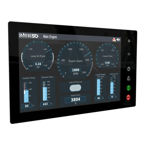
auto maskin
auto maskin Marine Pro Series User manual
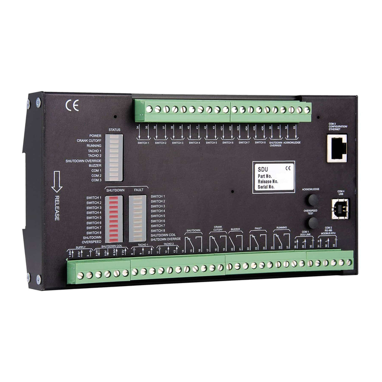
auto maskin
auto maskin Marine Pro 400 Series User manual
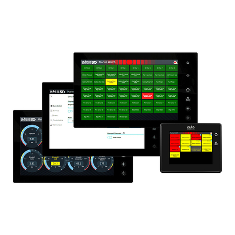
auto maskin
auto maskin Marine Watch S Series User manual

auto maskin
auto maskin Marine Pro 400 Series User manual
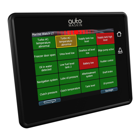
auto maskin
auto maskin LT Series User manual

auto maskin
auto maskin Marine Pro 400 Series User manual
auto maskin
auto maskin S Series User manual
auto maskin
auto maskin Marine Pro 400 Series User manual

auto maskin
auto maskin Marine Pro 200 Series User manual

auto maskin
auto maskin Marine Pro 400 Series User manual

