TABLE OF CONTENTS
Introduction 2. 7
Safety symbol and signalword review........................ 2
Prepadng yourgarage door........................................ 3
Toolsneeded............................................................... 3
Planning .................................................................. 4-5
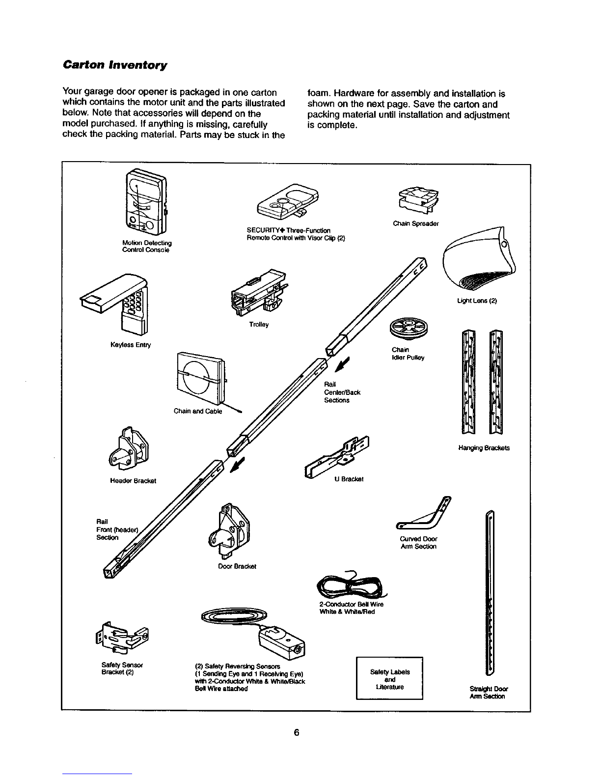
Carton inventory.......................................................... 6
Hardware inventory..................................................... 7
Assembly 8.11
Assemble the rail and installtrolley............................. 8
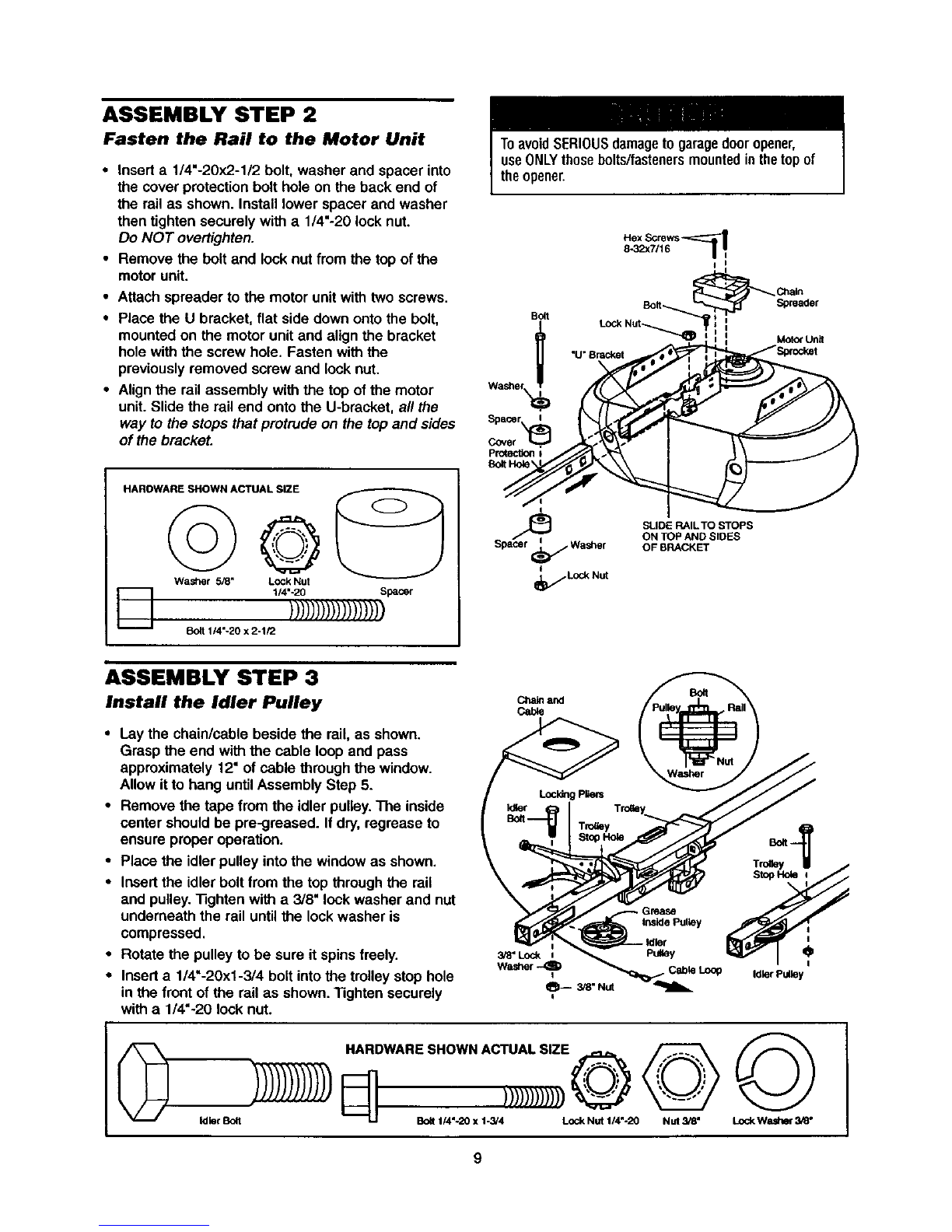
Fasten railto motorunitand installidler pulley..........9
Install chain/cable...................................................... 10
"nghtenthe chain....................................................... 11
Installation 11.27
Installationsafety instructions.................................... 11
Determine the header bracket location................12-13
Installthe header bracket.......................................... 14
Attach the railto the header bracket......................... 15
Positionthe opener ................................................... 16
Hang the opener ....................................................... 17
Installthe door control............................................... 18
Installthe lightsand lens........................................... 19
Attach the emergency release ropeand handle.......19
Electricalrequirements.............................................. 20
Installthe safety reversingsensor....................... 21-23
Fasten the door bracket....................................... 24-25
Connect the door arm to the trolley.....................26-27
Adjustment 28-30
Adjustthe travel limits............................................... 28
Adjustthe force......................................................... 29
Testthe safety reversalsystem................................. 30
Testthe safety reversingsensor............................... 30
Operation 31.34
Operationsafety instructions..................................... 31
Using yourgarage door opener ................................ 31
Using the wall-mountedDoor Control....................... 32
To open the door manually........................................ 32
Care of yourgarage door opener.............................. 33
Havinga problem?.................................................... 34
Programming 3.5-36
To add a hand-held remote control........................... 35
To erase all codes..................................................... 35
3-Function Remotes.................................................. 35
To add or change a Keyless Entry PIN ..................... 36
Repair Parts 37-38
Railassembly parts................................................... 37
Installationparts........................................................ 37
Motor unitassembly parts......................................... 38
Accessories 39
Warranty
Service Numbers
39
Back Cover
INTRODUCTION
Safety Symbol
and Signal Word Review
This garage door opener has been designedand testedto offer safe serviceprovided itis installed,operated,
maintainedand tested in strictaccordancewith the instructionsand warningscontainedin this manual.
Mechanical
Electrical
When you see these Safety Symbolsand Signal
Words on the followingpages, they willalert you to
the possibilityof serious injury or death if you do
not complywith the warningsthat accompanythem.
The hazard may come from somethingmechanical
or from alectdc shock. Read the warningscarefully.
When you see this Signal Word on the following
pages, itwillalert you tothe possibility of damage to
yourgarage door and/or the garage dooropener if
you do not complywith the cautionary statements
that accompany it. Read them carefully.
2