8
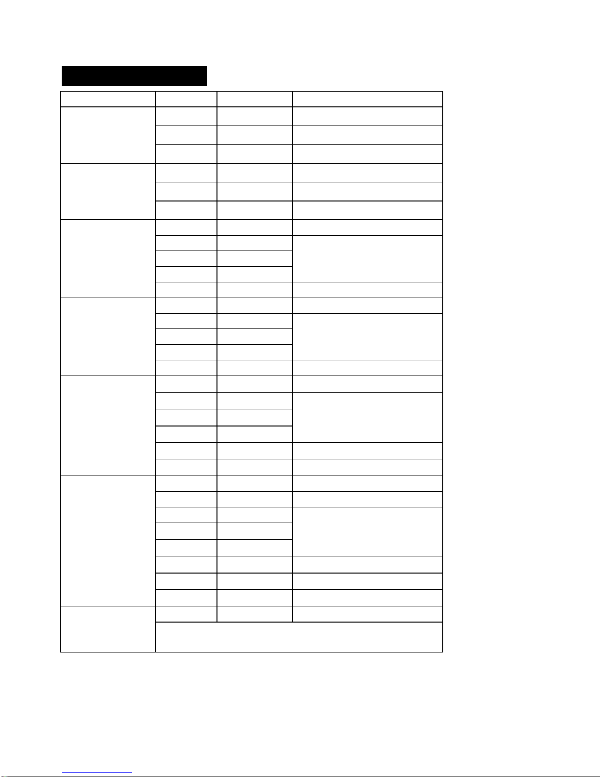
Function Range Resolution Accuracy
-4 to
1400ºF 1ºF ± (3% reading + 9ºF)Temperature
-20 to
760ºC 1ºC ± (3% reading + 5ºC)
NOTE: Accuracy specifications consist of two elements:
•(% reading) – This is the accuracy of the measurement circuit.
•(+ digits) – This is the accuracy of the analog to digital
converter.
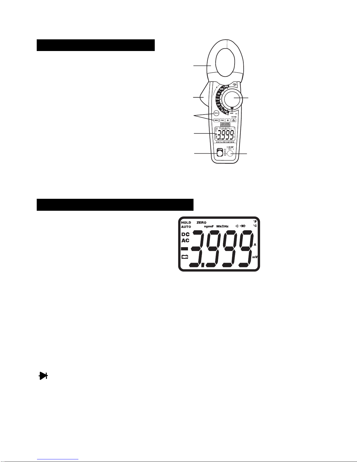
Clamp jaw opening 1.2” (30mm) approx.
Display 3-3/4 digits (4000 counts) backlit
Diode Test Test current of 0.3mA maximum,
open circuit voltage <3V DC typical
Continuity Check Audible signal will sound if the
resistance is less than 40
(approx.), test current <0.5mA
Temperature Sensor Requires type K thermocouple
Input Impedance 10M(VDC & VAC)
AC Response True rms (AAC and VAC)
ACV Bandwidth 50Hz to 400Hz
Crest Factor 3.0 in 40A and 400A ranges, 1.4 in
800A range (50/60Hz and 5% to
100% of range)
Overrange indication “OL” is displayed
Auto Power Off 25 minutes (approximately)
Polarity Automatic (no indication for
positive); Minus (-) sign for negative
Measurement Rate 2 times per second, nominal
PEAK Captures peaks>1ms
Low Battery Indication “BAT” is displayed if battery voltage
drops below operating voltage
Battery one 9 volt (NEDA 1604) battery
Operating Temperature 41oF to 104oF (5oC to 40oC)
Storage Temperature -4oF to 140oF (-20oC to 60oC)