Cray CX1 User manual

CRAY CX1 Personal Cluster
User Manual
CRAY CX1 Personal Cluster
Copyright © 2008. All rights reserved. Proprietary Information.
Page 1 of 74
CRAY CX1
High Performance Personal Cluster
User Manual
Revision 1.4

CRAY CX1 Personal Cluster
User Manual
CRAY CX1 Personal Cluster
Copyright © 2008. All rights reserved. Proprietary Information.
Page 2 of 74
CUSTOMER SERVICE
CRAY Customer Service will respond efficiently to communicate your information and issues to the
appropriate personnel. Be sure to mention the product serial # in order for the information to be
directed to the right personnel.
TELEPHONE SUPPORT:
Toll-Free: (866) 277-9CX1 (9291)
Local (Outside North America): (514) 789-9443
EMAIL:
When requesting technical support, please include the following:
Contact information (i.e. Full name, email address, phone number),
System serial number,
Description of the issue; please attach any data and/or log files that are available, as well as
any additional information that may help us assist you.

CRAY CX1 Personal Cluster
User Manual
CRAY CX1 Personal Cluster
Copyright © 2008. All rights reserved. Proprietary Information.
Page 3 of 74
Disclaimer Notice
The technical data contained in this document are proprietary to CRAY. No reproduction by
photocopy or storage or retrieval system of any part of the information supplied is permitted,
except by written authorization from CRAY. The information in this manual is subject to change
without notice and does not represent a commitment on the part of CRAY.
In no event will CRAY be liable for direct, indirect, special, incidental, speculative or
consequential damages arising from the use or inability to use this product or documentation, even
if advised of the possibility of such damages. In particular, CRAY shall not have liability for any
hardware, software, or data stored or used with the product, including the costs of repairing,
replacing, integrating, installing or recovering such hardware, software, or data.
MANUFACTURER is not responsible for any damage that occurs as a result of your failure to follow
the instructions that come with the MANUFACTURER product. A separate, detailed and
comprehensive Limited Warranty is provided with this product. The terms and conditions that are
contained therein supersede any prior agreements or representations, including representations
made in MANUFACTURER sales literature or advice given to you by MANUFACTURER or an agent or
employee of MANUFACTURER that may have been made in connection with your purchase or lease
of the MANUFACTURER product. No change to the conditions of this Limited Warranty is valid
unless it is made in writing and signed by an officer of MANUFACTURER.
Except as expressly set forth in the limited warranty, MANUFACTURER makes no other warranties
or conditions, express or implied, whether provided for by any applicable legislation, regarding the
product, its functionality, performance, intellectual property rights, including any implied
warranties of merchantability and fitness for a particular purpose. MANUFACTURER expressly
disclaims all warranties and conditions not stated in the limited warranty. Any implied warranties
that may be imposed by law are limited in duration to the limited warranty period.
Copyright ©2009 by CRAY Inc. All rights reserved. Printed in Canada
Manual Revision 1.4; Release Date: November, 2009.
Other products and companies referred to herein are trademarks or registered trademarks of their
respective companies or mark holders.

CRAY CX1 Personal Cluster
User Manual
CRAY CX1 Personal Cluster
Copyright © 2008. All rights reserved. Proprietary Information.
Page 4 of 74
Conventions Used in this Manual
Special attention should be given to the following symbols for proper installation and to prevent
damage done to the components or to personal injury.
It is extremely important to learn the correct and safe use of this product. Various kinds of cautionary
labels with wording and symbols are used in this manual where necessary. They are guides to:
Use this product safely
Prevent exposure to harmful and avoidable dangerous situations
Prevent damage to equipment
The following symbols are used throughout this document:
Warning: Be cautious when handling or servicing electrical components.
Electrostatic-Discharge (ESD) can damage electronic components. To prevent damage to your
system board, it is important to handle IC boards or modules very carefully.
Notes comprise additional information to assist the reader on how to use the equipment
correctly.
Conservation and ecology awareness.
Caution: This equipment is heavy and can cause injury if mishandled.
This equipment is sensitive and can be damaged if handled with unnecessary force.
Handle with care to prevent damage. Ensure sufficient manpower for transport

CRAY CX1 Personal Cluster
User Manual
CRAY CX1 Personal Cluster
Copyright © 2008. All rights reserved. Proprietary Information.
Page 5 of 74
REVISION RECORD TABLE
Revision Changes Pages
1.0 Initial Release
49
1.1 System Installation
56
1.2 FRU Lists
60
1.3 Troubleshooting
62
1.4
Certifications Logos added
CN5400 blade removed
CN4800 blade removed
CN5500 blade added

CRAY CX1 Personal Cluster
User Manual
CRAY CX1 Personal Cluster
Copyright © 2008. All rights reserved. Proprietary Information.
Page 6 of 74
TABLE OF CONTENTS
1INTRODUCTION....................................................................................................12
1.1QUALITY CERTIFICATIONS AND SAFETY..................................................................13
1.2ELECTRICAL SAFETY PRECAUTIONS ......................................................................14
1.3GENERAL SAFETY PRECAUTIONS..........................................................................14
1.4ELECTRICAL DISCHARGE PRECAUTIONS..................................................................15
1.5ENVIRONMENTAL STANDARDS.............................................................................15
1.6PRODUCT CHECKLIST.......................................................................................16
2SYSTEM INSTALLATION...........................................................................................17
2.1PEDESTAL INSTALLATION..................................................................................17
2.1.1UNPACKING ..............................................................................................17
2.1.2ASSEMBLY ................................................................................................19
2.1.3CABLING..................................................................................................21
2.1.4SYSTEM STARTUP ....................................................................................... 22
2.1.5ZONE DIVISION........................................................................................... 23
2.2RACKMOUNT INSTALLATION...............................................................................24
3SYSTEM OVERVIEW................................................................................................27
3.1CRAY CX1 CHASSIS OVERVIEW ............................................................................ 28
3.1.1INFINIBAND...............................................................................................31
3.1.2HCA CARD AND RISER CARD ...........................................................................32
3.1.3GIGABIT SWITCH ........................................................................................33
3.1.43.5” LCD TOUCH PANEL COMPUTER .................................................................34
3.1.5COOLING & ACTIVE NOISE CONTROL.................................................................36
3.1.6POWER SUPPLY..........................................................................................37
3.1.7DVD / USB PASSTHROUGH............................................................................. 38
3.2CN5500 COMPUTE BLADE..................................................................................39
3.2.1REMOVING THE BLADE COVER ........................................................................ 40
3.2.2CN5500 MOTHERBOARD................................................................................42
3.2.3CN5500 MOTHERBOARD SPECIFICATIONS............................................................ 43
3.2.4ACPI FEATURES..........................................................................................46
3.2.5INSTALLING CPU AND HEAT SINKS.................................................................... 48
3.2.6INSTALLING DIMMS......................................................................................51
3.2.7INSTALLING AND REMOVING A BLADE FROM THE CX1 CHASSIS................................... 53
3.3CS5504 STORAGE BLADE...................................................................................54
3.3.1CS5504H HOT-SWAP STORAGE BLADE................................................................54
3.3.2CS5504F FIXED STORAGE BLADE...................................................................... 54
3.4CV5501 VISUALIZATION BLADE............................................................................55
4TROUBLESHOOTING ..............................................................................................56
5APPENDIX 1: LCD DISPLAY INSTALLATION AND OPERATING GUIDE........................................58

CRAY CX1 Personal Cluster
User Manual
CRAY CX1 Personal Cluster
Copyright © 2008. All rights reserved. Proprietary Information.
Page 7 of 74
5.1SERVER CONFIGURATION ..................................................................................58
5.2USING THE LCD DISPLAY...................................................................................59
5.3MAIN SCREEN ................................................................................................59
5.4ALARM ........................................................................................................60
5.5CONTROLLING THE SYSTEM POWER...................................................................... 61
5.6CX1 SERVER MANAGER .....................................................................................61
5.7USING THE CONFIGURATION MANAGER..................................................................63
5.8COMPONENT STATUS....................................................................................... 66
5.9SCREENSAVER ...............................................................................................68
5.10STOPPING THE XG2WINCE PROGRAM ....................................................................68
5.11UPDATING THE LCD APPLICATION........................................................................70

CRAY CX1 Personal Cluster
User Manual
CRAY CX1 Personal Cluster
Copyright © 2008. All rights reserved. Proprietary Information.
Page 8 of 74
LIST OF FIGURES
Figure 2-1 Packaging................................................................................................... 18
Figure 2-2 Chassis Cart................................................................................................19
Figure 2-3 Chassis Assembly.......................................................................................... 20
Figure 2-4 CX4-to-CX4 InfiniBand Cable ............................................................................ 21
Figure 2-5 QSFP-to-CX4 InfiniBand Cable........................................................................... 21
Figure 2-6 System Startup ............................................................................................22
Figure 2-7 CX1 Zones .................................................................................................. 23
Figure 2-8 Rail Mounting Instructions...............................................................................25
Figure 2-9 Rackmounted CX1......................................................................................... 26
Figure 3-1 CRAY CX1 System .........................................................................................27
Figure 3-2 Front Exploded View .....................................................................................28
Figure 3-3 Rear Chassis View......................................................................................... 29
Figure 3-4 Front View ................................................................................................. 30
Figure 3-5 InfiniBand ..................................................................................................31
Figure 3-6 HCA & Riser Card for InfiniBand........................................................................32
Figure 3-7 16-Port Gigabit Switch ................................................................................... 33
Figure 3-8 LCD Touch Panel ..........................................................................................34
Figure 3-9 Serial Port Setting ........................................................................................ 35
Figure 3-10 LCD Display for the CX1 ................................................................................35
Figure 3-11 Fan Cooling System...................................................................................... 36
Figure 3-12 Power Supply.............................................................................................37
Figure 3-13 USB Passthrough .........................................................................................38
Figure 3-14 Front View of the CN5500-GE Blade..................................................................39
Figure 3-15 Sliding Blade Cover......................................................................................40
Figure 3-16 Inside View of a CN550 Blade.......................................................................... 41
Figure 3-17 CN5500 Motherboard Top View........................................................................43
Figure 3-18 Motherboard Layout.....................................................................................44
Figure 3-19 Block Diagram of the 5500 Series Processor Platform .............................................47
Figure 3-20 Installing CPU ............................................................................................48
Figure 3-21 CPU Install................................................................................................49
Figure 3-22 DIMM Install...............................................................................................52
Figure 3-23 Blade Release Latch Assembly.........................................................................53
Figure 3-24 Hot-Swap Storage Blade................................................................................54
Figure 3-25 Angle View of the Fixed Storage Blade ..............................................................54
Figure 3-26 Inside Top View of the Fixed Storage Blade.........................................................54
Figure 3-27 NVIDIA Quadro FX 4600 Graphics Card ...............................................................55
Figure 3-28 NVIDIA C1060 Tesla GPU Card .........................................................................55
Figure 3-29 Front View of CV5501 Blade ...........................................................................55

CRAY CX1 Personal Cluster
User Manual
CRAY CX1 Personal Cluster
Copyright © 2008. All rights reserved. Proprietary Information.
Page 9 of 74
LIST OF TABLES
Table 3-1 HCA Specifications.........................................................................................32
Table 3-2 CN5500 Specifications.....................................................................................43
Table 3-3 Jumper /LEDs ..............................................................................................44
Table 3-4 CN5500 Connectors........................................................................................45
Table 4-1 Troubleshooting............................................................................................57

CRAY CX1 Personal Cluster
User Manual
CRAY CX1 Personal Cluster
Copyright ©2008, Cray Inc. All rights reserved. Proprietary Information.
Page 10 of 74
About this Manual
This manual is written for system integrators, PC technicians and knowledgeable PC users. It provides
information for the installation and use of the CRAY CX1 Personal Cluster. This product is intended to
be professionally installed in an enterprise server environment. To protect the warranty of this unit, all
installations or modifications require qualified and certified technicians.
Organization of this Manual
The CRAY CX1 User Manual is organized according to the following Sections:
Section 1.0
INTRODUCTION: Details the CX1’s certifications and environmental conditions.
Section 2.0
SYSTEM INSTALLATION: Details the initial setup of the CX1.
Section 3.0
SYSTEM OVERVIEW: Details the various components comprising the CX1.
Section 4.0
SOFTWARE: Details the installation of all supported operating systems of the CX1.
Section 5.0
TROUBLESHOOTING: Details basic troubleshooting techniques for the CX1.
Section 6.0
APPENDIX: Details any additional information or resources for the CX1

CRAY CX1 Personal Cluster
User Manual
CRAY CX1 Personal Cluster
Copyright ©2008, Cray Inc. All rights reserved. Proprietary Information.
Page 11 of 74
Acronyms and Definitions
ACPI Advanced Configuration and Power Interface
CE European Compliance
CSA Canadian Standards Association
DBI Dynamic Bus Inversion (DBI)
EDC Enterprise Data Centers
FCC Federal Communications Commission (usually refers to the US agency)
GUI Graphical User Interface
HCA Host Channel Adapter
HPC High Performance Computing
IP Internet Protocol
KCC Korean Communications Comission
RAS Reliability, availability, and serviceability
RF Radio Frequency
RoHS Restriction of Hazardous Substances
PECI Platform Environment Control Interface
SDI Serial Digital Interface
TCP Transmission Control Protocol
TM2 Thermal Management 2
WEEE Waste Electrical and Electronic Equipment

CRAY CX1 Personal Cluster
User Manual
CRAY CX1 Personal Cluster
Copyright ©2008, Cray Inc. All rights reserved. Proprietary Information.
Page 12 of 74
1INTRODUCTION
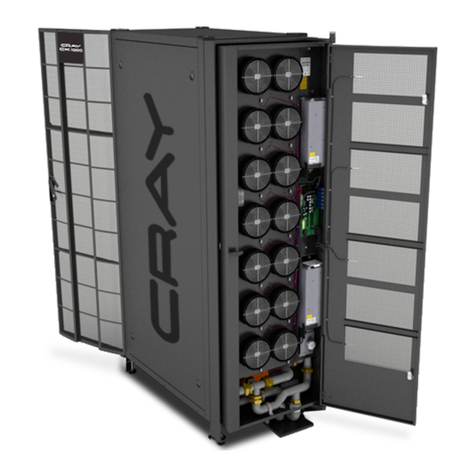
The CRAY CX1 High Performance Computer (HPC) is a compact, self-contained server which provides
power, cooling, management and networking functions. A single chassis can accommodate up to eight
blade units in various configurations. The CX1 is a versatile cluster configurable with:
Dual socket compute node
Graphic/GPU node
High-capacity hot swappable or fixed storage node
Data centers and specialized industries ranging from science applications, engineering applications,
medical applications and businesses requiring intensive resources for processing CPU intensive data,
need agile computing resources that they can use fully but can change and adapt as business needs
change. Administrators and developers need around the clock availability and reliability with the
ability to manage power and cooling costs, even as systems become more power hungry and facility
costs rise.
More complex processors using multi-core architectures that impact system sizing and creating greater
demands on I/O bandwidth usage, as well as server virtualization tools that affect processor, memory,
and I/O configurations per server have all contributed to a demand for a reliable system with ample
redundancy features to ensure reliability and cost effective solutions.
The CRAY CX1 was designed to meet these objectives in a real-time environment. The CX1 is the next
generation High Performance Personal Computing standard easy to deploy and user-friendly to operate.
The CX1 supports up to 8 nodes and up to 16 Intel Xeon 5500 series processors and supports up to 96GB
of DDR3, 1333MHz memory per node.

CRAY CX1 Personal Cluster
User Manual
CRAY CX1 Personal Cluster
Copyright ©2008, Cray Inc. All rights reserved. Proprietary Information.
Page 13 of 74
1.1 QUALITY CERTIFICATIONS AND SAFETY
The CX1 meets the following certification requirements for the license duration:
ISO 9001:2000
ISO 14001 RoHS5, RoHS6
FCC Regulation
KCC Regulation
CSA Regulation
CE
C-Tick
RoHS
WEEE Registrations in all applicable countries
Licensee shall adhere to local compliance and/or legal requirements in all countries served.
Warning: Be cautious when handling or servicing electrical components.

CRAY CX1 Personal Cluster
User Manual
CRAY CX1 Personal Cluster
Copyright ©2008, Cray Inc. All rights reserved. Proprietary Information.
Page 14 of 74
1.2 ELECTRICAL SAFETY PRECAUTIONS
Basic electrical safety precautions should be followed to protect you from harm, while preventing
damage to the unit:
Be aware of how to power on/off the system and the individual blades. As well, take note of
the room's emergency power-off switch, disconnection switch or electrical outlet. If an
electrical accident occurs, you can then quickly remove power from the system.
Do not work alone when working with high voltage components.
Power should always be disconnected from the system when removing or installing system
components such as the blades, switches, power supplies, etc.
When working around exposed electrical circuits, another person who is familiar with the
power-off controls should be nearby to switch off the power if necessary.
Use only one hand when working with powered-on electrical equipment. This is to avoid making
a complete circuit, which will cause electrical shock. Use extreme caution when using metal
tools, which can easily damage any electrical components or circuit boards they come into
contact with.
Do not use mats designed to decrease electrostatic discharge as protection from electrical
shock; instead, use rubber mats that have been specifically designed as electrical insulators.
The power cords on the system include a grounding plug, and therefore must be plugged into
grounded electrical outlets. The power input requirements are 120Vac or 200-240Vac only. For
more detail on the above, please see section 3.1.6.
If the Infiniband card or the Ethernet switch card is being installed or re-installed on the
system, always tighten the card’s thumbscrews using a tool so as to reduce the possibility of
removal of the card by unscrewing the thumbscrews by hand. Below the Ethernet switch card
are AC inlets which could be dangerous to an untrained person who may remove the card by
hand.
CMOS Battery: This battery must be replaced with the same or an equivalent type
recommended by the manufacturer (CR2032 Lithium 3V battery). Dispose of used batteries
according to the manufacturer's instructions.
1.3 GENERAL SAFETY PRECAUTIONS
Follow these rules to ensure general safety:
Keep the area around the system clean and free of clutter.
Place the blade module cover and any system components that have been removed away from
the system or on a table so that they are not accidentally stepped on.
While working on the system, do not wear loose clothing such as neckties or unbuttoned shirt
sleeves which can come into contact with electrical circuits or be pulled into a cooling fan.
Remove any jewelry or metal objects from your body, which are excellent metal conductors
that can create short circuits and harm you if they come into contact with printed circuit
boards or areas where power is present.
After accessing the inside of the system, replace the blade module's cover before installing it
back into the chassis.
Electrostatic-Discharge (ESD) can damage electronic components. To prevent damage to your
system board, it is important to handle IC boards or modules very carefully.

CRAY CX1 Personal Cluster
User Manual
CRAY CX1 Personal Cluster
Copyright ©2008, Cray Inc. All rights reserved. Proprietary Information.
Page 15 of 74
1.4 ELECTRICAL DISCHARGE PRECAUTIONS
Electrostatic discharge (ESD) is generated by two objects with different electrical charges coming into
contact with each other. An electrical discharge is created to neutralize this difference, which can
damage electronic components and printed circuit boards. The following measures are generally
sufficient to neutralize this difference before contact is made to protect your equipment from ESD:
Use a grounded wrist strap designed to prevent static discharge.
Keep all components and printed circuit boards (PCBs) in their antistatic bags until ready for
use.
Touch a grounded metal object before removing any PCB from its antistatic bag.
Do not let components or PCBs come into contact with your clothing, which may retain a
charge even if you are wearing a wrist strap.
Handle a board by its edges only; do not touch its components, peripheral chips, memory
modules or contacts.
When handling chips or modules, avoid touching their pins.
Put the mainboard and peripherals back into their antistatic bags when not in use.
1.5 ENVIRONMENTAL STANDARDS
For optimal operating conditions, the following guidelines must be followed:
Ambient Temperature Range: Operating: 10°C to 30°C
Non-operating/storage: -40°C to +70°C
Relative Humidity: Non-operating: 95%
Non-condensing at 30°C
Conservation and ecology awareness.
The CRAY CX1:
Does not require a dedicated computer room, and is 92% power efficient.
Uses regular office power outlets (20A – 110/240V).
Note: A fully-populated CX1 system requires 2 dedicated 20A (110/240V) circuits.

CRAY CX1 Personal Cluster
User Manual
CRAY CX1 Personal Cluster
Copyright ©2008, Cray Inc. All rights reserved. Proprietary Information.
Page 16 of 74
1.6 PRODUCT CHECKLIST
Verify that the checklist below corresponds to the equipment physically received.
Units Description
1 CX1 Chassis
1 to 8 Blade modules
1 to 4 Power supply modules
1 Documentation kit
1 Keyboard & Mouse
3 External USB (M/M) cables
1 to 8 Gigabit cables
1 to 8 (Optional) Infiniband cables
1 (Optional) Chassis cart
1 (Optional) Rack mounting rail kit

CRAY CX1 Personal Cluster
User Manual
CRAY CX1 Personal Cluster
Copyright ©2008, Cray Inc. All rights reserved. Proprietary Information.
Page 17 of 74
2SYSTEM INSTALLATION
The CRAY CX1 can be installed either in a pedestal or rack-mounted configuration.
2.1 PEDESTAL INSTALLATION
2.1.1 UNPACKING
Inspect the box that was shipped in and note the presence of any damage. If the chassis itself shows
damage, fill in the form and follow the instructions provided with the Quick Reference Guide package.
Decide on a suitable location for the rack unit that will hold the chassis. It should be located in a
clean, dust-free area that is well ventilated. Avoid areas where heat, electrical noise and
electromagnetic fields are generated. You will also need it placed near a grounded power outlet. Read
the "Rack Precautions" and "Server Precautions" in the next section.
The box that the unit was shipped in will include a pedestal assembly. Follow the steps in the order
given below to complete the installation process in the minimum amount of time. Please read this
section in its entirety before you begin the installation procedure outlined in the sections that follow.
This section describes the proper unpacking of the unit when received. Follow the directives below:
a) Unpack the boxes and locate the chassis cart
b) Unpack and locate the chassis
c) Unpack and locate the cables
d) Place the chassis on chassis cart
e) Install the blades
f) Connect the external cables securely
g) Power up the unit
This equipment is heavy and can cause injury if mishandled. This equipment is
sensitive and can be damaged if handled with unnecessary force. Handle with care
to prevent damage. Ensure sufficient manpower for transport.
Before unpacking, verify the status of the Tip and Tell sensors, present to indicate any
excessive impact during shipment. If the indicators are BLUE indicating excessive shock,
please contact CRAY immediately for instructions on how to proceed.

CRAY CX1 Personal Cluster
User Manual
CRAY CX1 Personal Cluster
Copyright ©2008, Cray Inc. All rights reserved. Proprietary Information.
Page 18 of 74
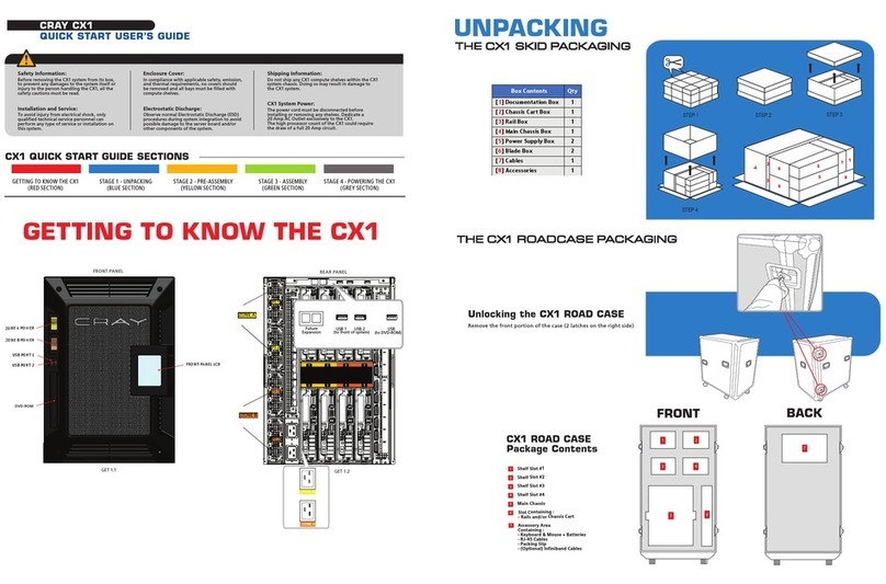
Figure 2-1 Packaging
Box Contents Qty
[1] Documentation Box 1
[2] Chassis Cart Box 1
[3] Rail Box 1
[4] Main Chassis Box 1
[5] Power Supply Box 2
[6] Blade Box 2
[7] Cables 1
[8] Accessories 1
1
7
8
2
5
5
6
6
4
3

CRAY CX1 Personal Cluster
User Manual
CRAY CX1 Personal Cluster
Copyright ©2008, Cray Inc. All rights reserved. Proprietary Information.
Page 19 of 74
2.1.2 ASSEMBLY
To install the CRAY CX1 as a desk-side system on its chassis cart, place the chassis onto the chassis
cart as shown in figure below.
Figure 2-2 Chassis Cart

CRAY CX1 Personal Cluster
User Manual
CRAY CX1 Personal Cluster
Copyright ©2008, Cray Inc. All rights reserved. Proprietary Information.
Page 20 of 74
The CX1 comes pre-assembled with the gigabit switch, fan assembly, and InfiniBand (optional)
components. The chassis cart, blades, power supply modules and external cables must be unpacked
and assembled on-site.
Install blades, making certain to hold the blade vertical and aligned with the slots of the chassis. Insert
slowly without forcing. Install the Power supply by sliding module(s) in the same careful manner.
Figure 2-3 Chassis Assembly
Be sure to handle blades with
extreme care, making sure that the
blade slides smoothly into the slot.
To ensure that the blade has been
properly installed, verify that the
handle’s locking mechanism is
secured into the notch on the
chassis, securing the blade in place.
ID Description
1 Gigabit switch
2 Infiniband switch (Optional)
3 Mid-guide plane
4 Power supply module
5 Compute blade
6 Chassis cart
Other manuals for CX1
1
Table of contents
Other Cray Desktop manuals
Popular Desktop manuals by other brands

Pinnacle Systems
Pinnacle Systems Dekocast Technical reference and service guide

Lenovo
Lenovo ThinkCentre A61e Uživatelská příručka
Nexcom
Nexcom nROK 7251 Series user manual

Lenovo
Lenovo ThinkCentre M90z Guia do usuário
Bosch
Bosch 1 687 023 850 Original instructions

IEI Technology
IEI Technology AFOLUX 915B Series user manual

Lenovo
Lenovo ThinkCentre Edge 72 user guide
Dell
Dell Precision T5500 Technical guide

Mitsubishi Electric
Mitsubishi Electric MXZ-18TV -E1 Service manual
ADLINK Technology
ADLINK Technology DLAP-8000 Series user manual
Winmate
Winmate FA30SB3-210 user manual
Lenovo
Lenovo ThinkStation S20 Manual do utilizador
