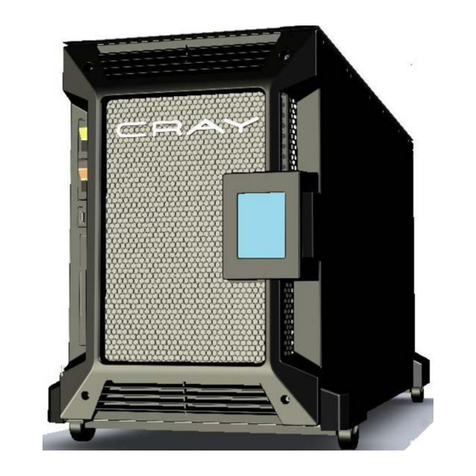
Cray XD1 Quick start guide

Cray XD1™ Hardware Installation
and Upgrade
Private
HR6–6402–E

© 2006 Cray Inc. All Rights Reserved. Unpublished Private Information. This unpublished work is protected to trade secret,
copyright and other laws. Except as permitted by contract or express written permission of Cray Inc., no part of this work or its
content may be used, reproduced or disclosed in any form.
U.S. GOVERNMENT RESTRICTED RIGHTS NOTICE
The Computer Software is delivered as "Commercial Computer Software" as defined in DFARS 48 CFR 252.227-7014.
All Computer Software and Computer Software Documentation acquired by or for the U.S. Government is provided with Restricted
Rights. Use, duplication or disclosure by the U.S. Government is subject to the restrictions described in FAR 48 CFR 52.227-14
or DFARS 48 CFR 252.227-7014, as applicable.
Technical Data acquired by or for the U.S. Government, if any, is provided with Limited Rights. Use, duplication or disclosure by the
U.S. Government is subject to the restrictions described in FAR 48 CFR 52.227-14 or DFARS 48 CFR 252.227-7013, as applicable.
Autotasking, Cray, Cray Channels, Cray Y-MP, GigaRing, LibSci, UNICOS and UNICOS/mk are federally registered
trademarks and Active Manager, CCI, CCMT, CF77, CF90, CFT, CFT2, CFT77, ConCurrent Maintenance Tools, COS, Cray Ada,
Cray Animation Theater, Cray APP, Cray Apprentice2, Cray C++ Compiling System, Cray C90, Cray C90D, Cray CF90, Cray EL,
Cray Fortran Compiler, Cray J90, Cray J90se, Cray J916, Cray J932, Cray MTA, Cray MTA-2, Cray MTX, Cray NQS, Cray Research,
Cray SeaStar, Cray S-MP, Cray SHMEM, Cray SSD-T90, Cray SuperCluster, Cray SV1, Cray SV1ex, Cray SX-5, Cray SX-6,
Cray T3D, Cray T3D MC, Cray T3D MCA, Cray T3D SC, Cray T3E, Cray T90, Cray T916, Cray T932, Cray UNICOS, Cray X1,
Cray X1E, Cray XD1, Cray X-MP, Cray XMS, Cray XT3, Cray XT4, Cray Y-MP EL, Cray-1, Cray-2, Cray-3, CrayDoc, CrayLink,
Cray-MP, CrayPacs, Cray/REELlibrarian, CraySoft, CrayTutor, CRInform, CRI/TurboKiva, CSIM, CVT, Delivering the power...,
Dgauss, Docview, EMDS, Gigaring, HEXAR, HSX, IOS, ISP/Superlink, Libsci, MPP Apprentice, ND Series Network Disk Array,
Network Queuing Environment, Network Queuing Tools, OLNET, RapidArray, RQS, SEGLDR, SMARTE, SSD, SUPERLINK,
System Maintenance and Remote Testing Environment, Trusted UNICOS, TurboKiva, UNICOS MAX, UNICOS/lc, and
UNICOS/mp are trademarks of Cray Inc.
Linux is a trademark of Linus Torvalds. Opteron is a trademark of Advanced Micro Devices, Inc. All other trademarks are the
property of their respective owners.

New Features
Cray XD1™ Hardware Installation and Upgrade HR6–6402–E
This rewrite of Cray XD1 Hardware Installation and Upgrade (HR6–6402) supports the general availability of
release 1.4 of the Cray XD1 product. It includes the WEEE compliance statement.


Record of Revision
Version Description
E May 2006
Supports the general availability of release 1.4 of the Cray XD1 product. Includes the
Waste Electrical and Electronic Equipment (WEEE) compliance statement.
D October 2005
Supports the general availability of release 1.3 of the Cray XD1 product. Minor
changes. Includes conversion to the new document format.
C July 2005
Supports the limited availability of release 1.3 of the Cray XD1 product. Minor
changes.
A, B April 2005
Supports release 1.2 of the Cray XD1 product.
HR6–6402–E Cray Private i


Contents
Page
Preface ix
Accessing Product Documentation . . . . . . . . . . . . . . . . . . . ix
Conventions . . . . . . . . . . . . . . . . . . . . . . . . . . x
Reader Comments . . . . . . . . . . . . . . . . . . . . . . . . xi
Cray User Group . . . . . . . . . . . . . . . . . . . . . . . . xi
Introduction [1] 1
Who Should Read This Manual . . . . . . . . . . . . . . . . . . . . 1
Scope of This Manual . . . . . . . . . . . . . . . . . . . . . . . 1
Units of Measurement . . . . . . . . . . . . . . . . . . . . . . . 1
Related Publications . . . . . . . . . . . . . . . . . . . . . . . 2
Regulatory Compliance Statements . . . . . . . . . . . . . . . . . . . 3
EMC Compliance Statements . . . . . . . . . . . . . . . . . . . . 3
United States . . . . . . . . . . . . . . . . . . . . . . . . 3
Canada . . . . . . . . . . . . . . . . . . . . . . . . . . 4
Safety Compliance: Warnings and Cautions . . . . . . . . . . . . . . . . 4
Sicherheitshinweis . . . . . . . . . . . . . . . . . . . . . . . 6
VCCI-A Compliance Statement . . . . . . . . . . . . . . . . . . . 7
WEEE Compliance Statement . . . . . . . . . . . . . . . . . . . . 7
Overview of Cray XD1 Installation [2] 9
About the Cray XD1 Computer . . . . . . . . . . . . . . . . . . . . 9
Cray XD1 Chassis . . . . . . . . . . . . . . . . . . . . . . . 9
Cray XD1 System . . . . . . . . . . . . . . . . . . . . . . . 11
Interprocessor Communications . . . . . . . . . . . . . . . . . . . 11
Overview of the Installation Process . . . . . . . . . . . . . . . . . . . 11
Required Tools and Equipment . . . . . . . . . . . . . . . . . . . . 14
HR6–6402–E Cray Private iii

Cray XD1™Hardware Installation and Upgrade
Page
Receiving Equipment [3] 15
Acclimating Equipment . . . . . . . . . . . . . . . . . . . . . . 15
Checking Inventory . . . . . . . . . . . . . . . . . . . . . . . . 15
Unpacking a System Cabinet . . . . . . . . . . . . . . . . . . . . . 15
Procedure 1: To unpack a system cabinet . . . . . . . . . . . . . . . . 16
Installing and Preparing a Cabinet [4] 19
Removing and Installing the Cabinet Side Panels . . . . . . . . . . . . . . . 19
Procedure 2: To remove cabinet side panels from a 42-VU cabinet . . . . . . . . 19
Procedure 3: To install cabinet side panels on a 42-VU cabinet . . . . . . . . . . 20
Procedure 4: To remove cabinet side panels from a 21-VU cabinet . . . . . . . . 20
Procedure 5: To install the cabinet side panels on a 21-VU cabinet: . . . . . . . . 20
Removing the Chassis Shipping Brackets . . . . . . . . . . . . . . . . . 20
Procedure 6: To remove the chassis shipping brackets . . . . . . . . . . . . 21
Positioning a Cabinet . . . . . . . . . . . . . . . . . . . . . . . 22
Routing Power Circuits . . . . . . . . . . . . . . . . . . . . . . . 23
Routing Power Circuits for Cray XD1 Chassis . . . . . . . . . . . . . . . 23
Routing Power Circuits for External Switches . . . . . . . . . . . . . . . 25
Installing the Ganging Kits . . . . . . . . . . . . . . . . . . . . . 26
Procedure 7: To install a ganging kit . . . . . . . . . . . . . . . . . 26
Stabilizing a Cabinet . . . . . . . . . . . . . . . . . . . . . . . 28
Installing the Anti-tip Foot . . . . . . . . . . . . . . . . . . . . . . 29
Procedure 8: To install the anti-tip foot . . . . . . . . . . . . . . . . . 29
Installing the Cabinet Trim on a 42-VU Cabinet . . . . . . . . . . . . . . . 30
Procedure 9: To install the cabinet trim: . . . . . . . . . . . . . . . . 30
Connecting Cables to the Cray XD1 System [5] 33
Cabling Guidelines . . . . . . . . . . . . . . . . . . . . . . . . 33
General Cabling Guidelines . . . . . . . . . . . . . . . . . . . . 33
Cable Routing Guidelines . . . . . . . . . . . . . . . . . . . . . 33
Routing Ethernet and Fibre Channel Cables . . . . . . . . . . . . . . . . 34
iv Cray Private HR6–6402–E

Contents
Page
Interconnecting the Cray XD1 Internal Networks . . . . . . . . . . . . . . . 35
Interconnecting the RapidArray Fabrics . . . . . . . . . . . . . . . . . 36
Interconnecting the Supervisory Network . . . . . . . . . . . . . . . . 36
Overview of the Supervisory Network . . . . . . . . . . . . . . . . 36
Connecting 100-Mbps Ethernet Ports . . . . . . . . . . . . . . . . . 36
Connecting the Cray XD1 System to External Devices . . . . . . . . . . . . . 37
PCI-X Card Connections and Numbering . . . . . . . . . . . . . . . . 38
Connecting to a LAN via NIC Ports . . . . . . . . . . . . . . . . . . 39
Procedure 10: To connect to a LAN via a NIC port . . . . . . . . . . . . 39
Connecting to External Storage Devices . . . . . . . . . . . . . . . . . 40
Fibre Channel Cable Bend Radii . . . . . . . . . . . . . . . . . . 40
Connecting Fibre Channel Ports . . . . . . . . . . . . . . . . . . 40
Procedure 11: To connect Fibre Channel ports: . . . . . . . . . . . . . 40
Connecting the JTAG Interface Card to a Personal Computer . . . . . . . . . . 41
Procedure 12: To connect the JTAG interface card . . . . . . . . . . . . 42
Connecting Power Cables . . . . . . . . . . . . . . . . . . . . . . 43
Procedure 13: To connect power cables . . . . . . . . . . . . . . . . 43
Upgrading a Cray XD1 System [6] 45
Upgrading a Cabinet . . . . . . . . . . . . . . . . . . . . . . . 45
Planning the Layout of Chassis and Switches . . . . . . . . . . . . . . . 45
Installing the Slide Rail Hardware . . . . . . . . . . . . . . . . . . 45
Routing Power Circuits . . . . . . . . . . . . . . . . . . . . . . 46
Installing a Chassis in a Cabinet . . . . . . . . . . . . . . . . . . . . 46
Safety Guidelines . . . . . . . . . . . . . . . . . . . . . . . 46
Before You Begin . . . . . . . . . . . . . . . . . . . . . . . . 47
Mounting a Chassis in a Cabinet . . . . . . . . . . . . . . . . . . . 47
Procedure 14: To mount a chassis in a cabinet . . . . . . . . . . . . . . 47
Reseating or Installing Disk Blades . . . . . . . . . . . . . . . . . . . 48
Procedure 15: To reseat disk blades . . . . . . . . . . . . . . . . . . 49
Procedure 16: To install disk blades . . . . . . . . . . . . . . . . . 50
HR6–6402–E Cray Private v

Cray XD1™Hardware Installation and Upgrade
Page
Installing External Switches . . . . . . . . . . . . . . . . . . . . . 51
Installing an Ethernet Switch . . . . . . . . . . . . . . . . . . . . 52
Procedure 17: To install an Ethernet switch . . . . . . . . . . . . . . 52
Installing a 24-port RapidArray Switch . . . . . . . . . . . . . . . . . . 53
Procedure 18: To install 24-port RapidArray switches . . . . . . . . . . . . 53
Installing Cabinet Blanking Panels . . . . . . . . . . . . . . . . . . . 58
Removing a Chassis from a Cabinet . . . . . . . . . . . . . . . . . . . 59
Procedure 19: To remove a chassis from a cabinet . . . . . . . . . . . . . 59
Appendix A Installation Checklist 61
Glossary 63
Index 67
Tables
Table 1. Related publications . . . . . . . . . . . . . . . . . . . . 2
Table 2. Overview of the installation process . . . . . . . . . . . . . . . 12
Table 3. Overview of the upgrade process . . . . . . . . . . . . . . . . 13
Table 4. PCI-X card connections to nodes . . . . . . . . . . . . . . . . . 38
Table 5. Installation checklist . . . . . . . . . . . . . . . . . . . . 61
Figures
Figure 1. On symbol . . . . . . . . . . . . . . . . . . . . . . . 4
Figure 2. Standby symbol . . . . . . . . . . . . . . . . . . . . . 4
Figure 3. VCCI-A Compliance Statement . . . . . . . . . . . . . . . . . 7
Figure 4. WEEE compliance statement . . . . . . . . . . . . . . . . . 8
Figure 5. Cray XD1 chassis, front view . . . . . . . . . . . . . . . . . 10
Figure 6. Cray XD1 chassis, rear view . . . . . . . . . . . . . . . . . . 10
Figure 7. Cabinet shipping crate . . . . . . . . . . . . . . . . . . . 16
Figure 8. Installing the ramp . . . . . . . . . . . . . . . . . . . . 18
Figure 9. Chassis shipping bracket, right side . . . . . . . . . . . . . . . 21
vi Cray Private HR6–6402–E

Contents
Page
Figure 10. Cabinet position relative to floor cutouts . . . . . . . . . . . . . . 23
Figure 11. Power circuit routing . . . . . . . . . . . . . . . . . . . 25
Figure 12. Installing the half joiners . . . . . . . . . . . . . . . . . . 27
Figure 13. Attaching the joiner plate . . . . . . . . . . . . . . . . . . 28
Figure 14. System cabinet anti-tip foot . . . . . . . . . . . . . . . . . 29
Figure 15. Lowering the crown into the right-side vertical trim piece . . . . . . . . 31
Figure 16. System cabinet with the crown trim installed . . . . . . . . . . . . 31
Figure 17. Filler trim piece . . . . . . . . . . . . . . . . . . . . . 32
Figure 18. Ethernet and Fibre Channel cable management . . . . . . . . . . . . 35
Figure 19. Connect an Ethernet port . . . . . . . . . . . . . . . . . . 37
Figure 20. Numbering of NIC slots and ports . . . . . . . . . . . . . . . 38
Figure 21. Connect a NIC port . . . . . . . . . . . . . . . . . . . . 40
Figure 22. Connect a Fibre Channel port . . . . . . . . . . . . . . . . . 41
Figure 23. Ports on the JTAG interface card . . . . . . . . . . . . . . . . 41
Figure 24. Connect the JTAG interface card to a PC . . . . . . . . . . . . . . 42
Figure 25. Connect a power cable . . . . . . . . . . . . . . . . . . . 44
Figure 26. Align rails . . . . . . . . . . . . . . . . . . . . . . . 48
Figure 27. Install chassis . . . . . . . . . . . . . . . . . . . . . . 48
Figure 28. Disk blade with two SATA disk drives . . . . . . . . . . . . . . 49
Figure 29. Install a disk blade . . . . . . . . . . . . . . . . . . . . 51
Figure 30. Install Ethernet switch . . . . . . . . . . . . . . . . . . . 52
Figure 31. RapidArray switch and mounting hardware, front view . . . . . . . . . 54
Figure 32. RapidArray switch and mounting hardware, rear view . . . . . . . . . 55
Figure 33. RapidArray switch with mounting bracket (detail) . . . . . . . . . . 56
Figure 34. Cable troughs, side view (cabinet side panels not shown) . . . . . . . . . 57
Figure 35. Install cabinet blanking panels . . . . . . . . . . . . . . . . . 58
Figure 36. Disconnect power . . . . . . . . . . . . . . . . . . . . 59
HR6–6402–E Cray Private vii


Preface
The information in this preface is common to Cray documentation provided with
this software release.
Accessing Product Documentation
With each software release, Cray provides books and man pages, and in
some cases, third-party documentation. These documents are provided in the
following ways:
CrayDoc The Cray documentation delivery system that allows you to
quickly access and search Cray books, man pages, and in some
cases, third-party documentation. Access this HTML and PDF
documentation via CrayDoc at the following locations:
•The local network location defined by your system
administrator
•The CrayDoc public website: docs.cray.com
Man pages Access man pages by entering the man command followed by the
name of the man page. For more information about man pages,
see the man(1) man page by entering:
%man man
Third-party documentation
Access third-party documentation not provided through
CrayDoc according to the information provided with the
product.
HR6–6402–E Cray Private ix

Cray XD1™Hardware Installation and Upgrade
Conventions
These conventions are used throughout Cray documentation:
Convention Meaning
command This fixed-space font denotes literal items, such as file
names, pathnames, man page names, command names, and
programming language elements.
variable Italic typeface indicates an element that you will replace with a
specific value. For instance, you may replace filename with the
name datafile in your program. It also denotes a word or
concept being defined.
user input This bold, fixed-space font denotes literal items that the user
enters in interactive sessions. Output is shown in nonbold,
fixed-space font.
[ ] Brackets enclose optional portions of a syntax representation for
a command, library routine, system call, and so on.
... Ellipses indicate that a preceding element can be repeated.
name(N) Denotes man pages that provide system and programming
reference information. Each man page is referred to by its name
followed by a section number in parentheses.
Enter:
%man man
to see the meaning of each section number for your particular
system.
x Cray Private HR6–6402–E

Preface
Reader Comments
Contact us with any comments that will help us to improve the accuracy and
usability of this document. Be sure to include the title and number of the
document with your comments. We value your comments and will respond to
them promptly. Contact us in any of the following ways:
E-mail:
Telephone (inside U.S., Canada):
1–800–950–2729 (Cray Customer Support Center)
Telephone (outside U.S., Canada):
+1–715–726–4993 (Cray Customer Support Center)
Mail:
Customer Documentation
Cray Inc.
1340 Mendota Heights Road
Mendota Heights, MN 55120–1128
USA
Cray User Group
The Cray User Group (CUG) is an independent, volunteer-organized
international corporation of member organizations that own or use Cray Inc.
computer systems. CUG facilitates information exchange among users of Cray
systems through technical papers, platform-specific e-mail lists, workshops, and
conferences. CUG memberships are by site and include a significant percentage
of Cray computer installations worldwide. For more information, contact your
Cray site analyst or visit the CUG website at www.cug.org.
HR6–6402–E Cray Private xi


Introduction [1]
This chapter describes the intended audience for this manual and its scope, and
lists the related publications.
1.1 Who Should Read This Manual
This manual is intended for systems engineers or technicians who have
experience in installing computer system hardware into a computer room with a
controlled environment.
1.2 Scope of This Manual
This manual introduces you to the Cray XD1 computer and describes how to
install and cable Cray XD1 hardware components. For more details on the
hardware components in a Cray XD1 chassis, see Cray XD1 System Overview
(S–2429). For the information required to prepare your site for a Cray XD1
installation, see Cray XD1 Site Planning (HR6–6401). For the power-on and
commissioning procedures that bring a Cray XD1 system into service, see Cray
XD1 System Administration (S–2429).
For hardware maintenance procedures, see the Field Replacement
Procedures that are packaged with replacement parts. Note that the product
warranty requires that all Cray XD1 hardware be maintained only by Cray
service personnel, service providers authorized by Cray, or customers
who are trained on Cray XD1 hardware. See the CRInform website at
http://crinform.cray.com/xd/ for information on Cray XD1 training
programs and service support.
1.3 Units of Measurement
In most cases, this manual provides both U.S. and metric measurements, listing
the U.S. measurement first. However, there are some exceptions—mostly
regarding cabinet sizes and vertical units—where this manual provides only U.S.
units. This is consistent with industry–standard usage.
HR6–6402–E Cray Private 1

Cray XD1™Hardware Installation and Upgrade
1.4 Related Publications
Refer to the publications in Table 1, page 2 for more information on the Cray XD1
computer and the Active Manager software.
Table 1. Related publications
Publication title Brief description
Cray XD1 Release Description (S–2453) Identifies the main new features and
enhancements in a particular release
of the product. Includes information
about the hardware, embedded
software, and Linux-based software of
the system.
Cray XD1 System Overview (S–2429) Overview of the Cray XD1 computer
and a description of its hardware and
software components.
Cray XD1 Site Planning (HR6–6401) Guidelines on planning and preparing
your facility for a Cray XD1
installation.
Cray XD1 RapidArray Interconnect
Topologies (HR6–6425) Guidelines on cabling Cray XD1
hardware components in RapidArray
interconnect topologies.
Cray XD1 System Administration
(S–2430) System commissioning,
administration, and monitoring
procedures. Also job submission and
management procedures.
Cray XD1 Programming (S–2433) Development tools on a Cray
XD1 system and the application
programming interface for the FPGA
application acceleration processor.
Cray XD1 FPGA Development (S–6400) Overview of the process and tools for
developing logic files for the FPGA
application acceleration processor.
2 Cray Private HR6–6402–E

Introduction [1]
1.5 Regulatory Compliance Statements
The Cray XD1 computer complies with the following regulations:
•EMC
–Three-phase power supply: FCC part 15 Class A, ICES-003 Class A
–Single-phase power supply: FCC part 15 Class A, ICES-003 Class A,
EN55022, C1SPR22, EN55024
•Safety
–Three-phase power supply: UL 60950-1, CAN/CSA-C22.2 No.60950-1
–Single-phase power supply: UL 60950-1, CAN/CSA-C22.2 No.60950-1,
EN60950-1, IEC60950-1
•VCCI-A
•WEEE Compliance
Do not make any mechanical or electrical modifications to the equipment that
are not approved by Cray Inc. Cray Inc. is not responsible for the regulatory
compliance of a Cray product with unapproved mechanical or electrical
modifications.
1.5.1 EMC Compliance Statements
This section includes the EMC compliance statements for the United States and
Canada.
1.5.1.1 United States
This equipment has been tested and found to comply with the limits for a
Class A digital device, pursuant to Part 15 of the FCC Rules. These limits are
designed to provide reasonable protection against harmful interference when the
equipment is operated in a commercial environment. This equipment generates,
uses, and can radiate radio frequency energy, and if it is not installed and used
in accordance with the instruction manual, it may cause harmful interference to
radio communications. Operation of this equipment in a residential area is likely
to cause harmful interference, in which case the user will be required to correct
the interference at his own expense.
HR6–6402–E Cray Private 3

Cray XD1™Hardware Installation and Upgrade
1.5.1.2 Canada
This Class A digital apparatus complies with Canadian ICES-003.
Cet appareil numérique de la classe A est conforme àla norme NMB-003 du
Canada.
1.5.2 Safety Compliance: Warnings and Cautions
The following symbols are used in this manual and on the product.
Warning: Hazardous voltages are present. To reduce the risk of electric shock
and danger to personal health, follow the instructions.
!
Caution: There is a risk of personal injury, equipment damage, or loss of data.
Follow the instructions.
On (Figure 1, page 4). Power is applied to the system, if the power cord plug is
connected to the power source.
Figure 1. On symbol
Standby (Figure 2, page 4). Power is in Standby mode. Power is not removed
from the device until the power cord plug is disconnected from the power source.
Figure 2. Standby symbol
For your protection, adhere to the following safety precautions during
installation and maintenance of the Cray XD1 computer.
4 Cray Private HR6–6402–E
Other manuals for XD1
1
Table of contents
Other Cray Desktop manuals
