Creo Medical 7-EMR-050 User manual

Page 1 of 35
Instructions for Use
Electrosurgical Generator
CAUTION: Federal law restricts this device to sale by or on the order of a physician
Reference (model): 7-EMR-050. Language: English.
For use with Creo Medical accessories and surgical instruments only.
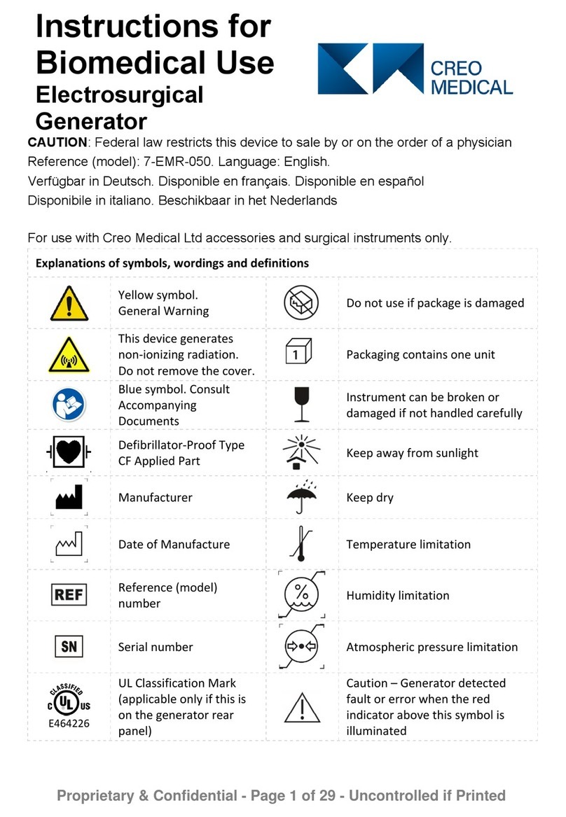
Explanations of symbols, wordings and definitions
Yellow symbol.
General Warning
Do not use if package is damaged
This device generates
non-ionizing radiation.
Do not remove the cover.
Packaging contains one unit
Blue symbol. Consult
Accompanying
Documents
Instrument can be broken or
damaged if not handled carefully
Defibrillator-Proof Type
CF Applied Part
Keep away from sunlight
Manufacturer
Keep dry
Date of Manufacture
Temperature limitation
Reference (model)
number
Humidity limitation
Serial number
Atmospheric pressure limitation
E464226
UL Classification Mark
(applicable only if this is
on the generator rear
panel)
Caution – Generator detected
fault or error when the red
indicator above this symbol is
illuminated
Mains inlet power supply
fuses
Do not dispose of the
Electrosurgical Generator in
normal waste

Page 2 of 35
Explanations of symbols, wordings and definitions
Equipotentiality
2797
CE marking for the generator
CUT Settings for cutting
function COAG Settings for coagulation function
Cutting Waveform Active
Coagulation Waveform Active
MRI Unsafe
Output from the Electrosurgical Generator
Transportation, this
symbol appears next to
the symbols indicating
environment limitations
during transportation
Storage, this symbol appears next
to the symbols indicating
environment limitations during
storage before and between uses
RS2
An example of a
proprietary surgical
accessory for use with
this Electrosurgical
Generator
Interface
Cable
A proprietary accessory cable that
connects the generator output
socket to the proximal end of the
surgical accessory.
Non-ionizing radiation hazard from attached surgical accessory when
activated
Rx Only
(USA)
Caution: US Federal law restricts this device to sale by or on the
order of a physician
Consult instructions for use

Page 3 of 35
Safety Instructions
Intended Use
The Electrosurgical Generator is intended to provide radiofrequency (RF) electrosurgical
energy for cutting and microwave energy (MW) for coagulation (hemostasis, cauterization)
and ablation of soft tissue, and is for use only with appropriate Creo Medical Instruments and
accessories
Indications and Contraindications
Indications for Use and Contraindications depend on the appropriate Creo Instrument that is
used with the Electrosurgical Generator. Please refer to the Instructions for Use for the
Instrument intended to be connected to the Electrosurgical Generator.
It is recommended that the Electrosurgical Generator and Instruments are not used in patients
who have electronic implants such as cardiac pacemakers without first consulting a qualified
professional (e.g. cardiologist).
User Qualification
The operator of the Electrosurgical Generator and Instruments must be a physician or medical
personnel under the supervision of a physician and must have received sufficient training in
clinical electrosurgical techniques. This manual does not explain or discuss clinical endoscopic
procedures.
Training in the operation of the Creo Medical Electrosurgical Generator is recommended and
available from the manufacturer.

Page 4 of 35
Safety Instructions
Instructions for Use
These Instructions for Use contain essential information on how to use the
Electrosurgical Generator. Before use, study this document thoroughly and refer to
it whenever in doubt. If you have any questions regarding these Instructions for Use
or the Electrosurgical Generator in general, contact Creo Medical.
Please also refer to the manufacturer’s instructions for use that are supplied with
the footswitch.
Warnings
Indicate a hazardous situation which, if not avoided, may result in death or injury to the
patient or user.
Cautions
Indicate a hazardous situation which, if not avoided, may result in damage to the
Electrosurgical Generator, Instrument in use, or minor injury of the patient or user.
Important Safety Warnings
Warnings
Safe and effective Electrosurgery is dependent not only on the equipment design but
also on factors that are directly under the control of the user. The user should be
qualified and experienced in relevant clinical endoscopic electrosurgical techniques.
Use this Electrosurgical Generator only for indications specified in the Instructions
for Use of the appropriate Creo Instrument and operate the Instrument in
accordance with the Instructions for Use.
Using the Electrosurgical Generator and Instruments outside their intended use may
lead to unintended clinical effects with risk of injury or death to the patient.
Use this Electrosurgical Generator only with appropriate Creo Instruments, Interface
Cables and footswitch specified for use with this Electrosurgical Generator.
Use of non-Creo Medical instruments and accessories may lead to unintended
clinical effects with risk of injury or death to the patient.
Do not use the Electrosurgical Generator or an Instrument if either appears to be
damaged.

Page 5 of 35
Safety Instructions
If liquid is spilled on the Electrosurgical Generator or the connectors, including the
connectors of the Interface Cable or Instruments, immediately cease operation,
switch Electrosurgical Generator off, and disconnect the Electrosurgical Generator at
the wall socket. If liquid is spilled on the Electrosurgical Generator or the connectors,
including the connectors of the Interface Cable or Instruments, there is a risk of
electrical shock to patient or user and/or this may lead to unintended clinical effects
with risk of injury or death to the patient.
Do not activate the Electrosurgical Generator while the Instrument tip or connectors
of the Interface Cable are in unintentional contact with tissue; for example, if
someone is touching the tip of the Instrument or when the Instrument tip is not in
direct view of the endoscopist or surgeon.
To avoid or reduce the chance of unintended clinical effects during electrosurgery,
please ensure that:
xthe patient cannot come into contact with grounded metal parts or parts with
appreciable capacitance to electrical ground such as operating table supports.
xall patient monitoring electrodes need to be placed as far as possible from surgical
electrodes when electrosurgical and physiological equipment is used
simultaneously on the same patient.
xneedle-type monitoring electrodes are not used.
xmonitoring systems with high-frequency current limiting devices are used.
Activation of the Electrosurgical Generator will result in the delivery of energy that
may cause unintended tissue effects.
Use of radio frequency energy particularly when cutting tissue may result in
neuromuscular stimulation resulting in unintended movement of target tissue.
Do not use in oxygen-rich environments, in the presence of flammable gases (e.g.
flammable anesthetics or gastrointestinal gases) or in the presence of flammable
liquids or other flammable materials. Ensure that flammable liquids are not pooled.
The Instruments connected to the Electrosurgical Generator and the Electrosurgical
Generator itself can be ignition sources. Using them in oxygen-rich environments or
the presence of flammable gases or liquids poses the risk of explosion or fire.
There is a risk of pooling of flammable solutions under the patient or in body
depressions such as the umbilicus, and in body cavities such as the vagina. Any fluid
pooled in these areas should be mopped up before the Electrosurgical Generator is
used.
During electrosurgery smoke may be produced, use of smoke-plume extraction is
advised if this occurs
Do not open the cover of the Electrosurgical Generator or modify hardware or
software in any way. Servicing of the Electrosurgical Generator must only be
performed by Creo Medical Ltd personnel or their designated representative.

Page 6 of 35
Safety Instructions
Modification or opening of the Electrosurgical Generator by unqualified persons may
result in electrical shock and will violate the warranty of the Electrosurgical
Generator.
In the event of failure of the Electrosurgical Generator, there is a risk of undesirable
rise in output power that might cause unintended tissue effects. To minimize
possible failure of the Electrosurgical Generator, have the device checked for safety
and calibration once a year.
In the event of a malfunction or failure, immediately cease treatment and switch the
Electrosurgical Generator off using the On / Off Power switch on the Rear Panel or
by disconnecting the power supply cord from the Electrosurgical Generator. In
emergencies, disconnecting the Instrument from the Interface Cable may also
terminate treatment and electrosurgical energy delivery.
To avoid risk of electric shock the Electrosurgical Generator must be connected via
its ac power cord to mains supply with a protective earth.
To avoid risk of fire replace fuses only as marked.
USA only: Grounding reliability can only be achieved when the equipment receptacle
is marked “Hospital Grade”.
Cybersecurity is a risk for all software-controlled devices with an access port. Access
to the generator's RS232 port is restricted to Creo personnel for routine software
updates and upgrades. Do not attempt to access this port for any reason, as
unauthorized access may result in loss of system function.
RFID emitters/readers transmit signals that might cause electromagnetic
interference that could disrupt the operation of the Creo Electrosurgical System.
Keep all RFID equipment at least 1 m away from this device system. Be aware that
RFID emitters can be portable or hidden in the room or building structure.

Page 7 of 35
Safety Instructions
The Electrosurgical Generator contains no user serviceable parts. To avoid risk of
electric shock and equipment malfunction do not remove any cover.
Modification or opening of the generator by unqualified persons may result in
electrical shock and will breach warranty of the generator.
Microwave energy should be not be applied to persons wearing metallic jewelry or
clothing containing metallic material. Hearing aids should be removed. Patients with
implanted electronic devices and/or electrodes should be excluded from treatment
with microwaves and from areas where the microwave equipment is operated. For
patients with cardiac pacemakers or other active implants, a possible hazard exists
due to interference with the action of the pacemaker or the pacemaker may be
damaged, and when in doubt, approved qualified advice should be obtained.
Caution
Disconnecting the Instrument from the Interface Cable while cut or coagulation are
activated poses the risk of burns when touching the connector of the Interface
Cable. Avoid touching the connectors of the Interface Cable at all times.

Page 8 of 35
Device Description
Front Panel
1. On / Standby Button and LED
2. Warning indicator
3. Symbol: Consult Accompanying
Documents
4. + / - Control Buttons
5. Menu control button
6. Display
7. Cut indicator LED (yellow)
Coagulation indicator LED (blue)
Microwave indicator LED (flashing blue)
8. Symbol Defibrillation-proof type CF applied
part
9. Output connection socket
Rear Panel
10. On / Off Power switch
11. AC inlet
12. Programming port
(service use only)
13. Footswitch connection socket
14. Label with product name and
model number
15. Equipotential connection
14 11 10 12
13
15

Page 9 of 35
Device Description
The Electrosurgical Generator comprises:
- Mains-powered electrosurgical unit intended for operating theatre and endoscopy suite use.
- Output:
• Bipolar RF power at 400 kHz at up to 200 W
• Microwave power at 5.8 GHz up to 62 W.
• Type CF Defibrillator proof Patient Circuit.
- Front panel interface comprising:
• A vacuum fluorescent display (VFD),
• Membrane-type control keys
• LEDs to indicate status and warnings.
- Rear panel connection for 2-pedal + center button footswitch for:
• Activation of the cut and coagulate outputs
• Footswitch-operated menu navigation and setting control.
- Rear panel connection for 2-pedal + center button footswitch for:
• Adjustable power for the RF output.
• Adjustable power for the microwave output.
The Electrosurgical Generator provides output to a single accessory cable capable of delivering
two different frequencies to a dedicated applicator for:
-Conventional electrosurgical unit RF frequencies for providing precise, low thermal margin
cutting.
- Microwave waveforms in the 5.8 GHz ISM (Industrial, Scientific and Medical) frequency band
for delivering controlled-depth coagulation.
Both waveform types are bipolar, confining the zone of electrosurgical effect exclusively to the
point of contact between tissue and applicator tip. There is no requirement for use of a patient
return pad.

Page 10 of 35
Set-up
Warning
The Electrosurgical Generator must always be connected to an AC power supply with
a protective ground (earth). Do not connect the power supply cord (also referred to
as an AC power cord) if it appears damaged or contaminated, if it has been modified,
or if it does not meet the requirement specified in the product specification table in
this Instructions for Use, as there is a risk of electrical shock to the patient or user.
USA only: Grounding reliability can only be achieved when the equipment receptacle
is marked “Hospital Grade”.
Condensation may occur when the unit is moved from a cold area into an area
intended for its use. Allow the Electrosurgical Generator to acclimatize before
connecting the power supply cord and/or turning the Electrosurgical Generator ON.
Condensation in the Electrosurgical Generator may cause a fault to occur if the
Electrosurgical Generator is turned ON.
The Electrosurgical Generator weighs approx. 35 lb. (16 kg) and the weight is not
evenly distributed. Care should be taken when lifting the generator.
Caution
The Electrosurgical Generator may cause electrical interference with other
equipment. Operation of the Electrosurgical Generator may be affected adversely
due to interference from other equipment. If interference occurs:
• Increase the distance between the Electrosurgical Generator and the suspected
interfering equipment in order to reduce interference.
• Ensure that Electrosurgical Generator cables and connected Instruments are
kept as far away as possible from other equipment cables.
The Electrosurgical Generator, Instruments, accessories, footswitch, and their
connection cables should be positioned such that damage or accidental activation is
avoided and that they do not present a tripping hazard.
There must be clearance of at least 9 cm (3.5 inches) to the rear of the
Electrosurgical Generator to allow for room for footswitch cable, AC power supply
cord, and for exhausting of air from the Electrosurgical Generator.
The Electrosurgical Generator is equipped with internal cooling fans. The cooling air
intakes are located towards the front both on the underside and on the on the right-
hand side wall of the Electrosurgical Generator as viewed from the front of the
Electrosurgical Generator. Do not allow these areas to be blocked.

Page 11 of 35
Set-up
STEP 1.
The Electrosurgical Generator should be positioned on a flat, horizontal
worktop or suitable trolley such that the Front Panel is visible, and the Display
are easy to read; controls are readily accessible; and Instruments can be
connected for their intended use
STEP 2.
The Electrosurgical Generator should always be positioned so that it is
possible to switch the unit off by using the On / Off Power switch (10) on the
Rear Panel of the Electrosurgical Generator or by disconnecting the AC power
supply cord.
STEP 3.
Before connecting the AC power supply cord ensure the On / Off Power
switch (marked ‘I’ and ‘O’) above the AC inlet (10) for the power supply cord
on the Rear Panel is set to the off position with the part of the switch marked
‘O’ pushed inwards.
STEP 4. Connect the AC power supply cord to the AC inlet (10).
STEP 5.
Connect the AC power supply cord directly to a suitably rated AC wall socket.
Do not connect to AC adaptors or extension cords. Use of these may lead to
faulty operation or loss of protective electrical grounding.
STEP 6. The footswitch is connected to the Footswitch connection socket (13) on the
Rear Panel of the Electrosurgical Generator.
STEP 7. Secure the Footswitch connection and cable by engaging and tightening the
retention ring on the footswitch plug to the Footswitch connection socket.
STEP 8.
Allow the footswitch connection cable to drape down at the rear of the
Electrosurgical Generator away from the patient and ensure that it does not
present a tripping hazard.
STEP 9.
Always place the Footswitch near the feet of the user such that deliberate
action by the user is required to activate the intended output from the
Electrosurgical Generator.
If needed, the Creo Electrosurgical Generator can be connected to the external grounding
system of the room via the standard Equipotential terminal pin (15) on the back of the
generator using a connecting cable designed for this purpose. External grounding removes the
hazards presented by low frequency leakage currents in the instance of a defective grounding
system within the room.

Page 12 of 35
Normal Use
Warning
Do not activate the output when the Instrument is in contact with or in close
proximity to metallic objects or other medical devices.
Do not use in combination with other electrosurgical generators.
Contact with other medical devices may cause burns to the patient.
Avoid touching the Output connection socket (9), connectors of the Interface Cable,
and the tip of the Instrument at all times.
The RF output sends a RF signal once per second to detect the connection of an
instrument that may be noticeable when touching the Output connection socket.
Use of energy for cutting and coagulation should be delivered at the minimum
power and for the minimum time necessary to complete the procedure. Use of
excessive energy and/or application for extended time, may result in patient injury
due to excessive penetration and lateral spread of thermal effects.
Turning ON the Electrosurgical Generator
STEP 1.
To turn ON the Electrosurgical Generator, on the Rear Panel push the part
of the On / Off Power switch (10) marked ‘I’ inwards.
Immediately after turning ON the Electrosurgical Generator, the red
warning indicator LED (2) on the Front Panel of the Electrosurgical
Generator will illuminate, briefly turn off, and then illuminate again for a
few more seconds. Thereafter the red Warning indicator LED (2) will
switch off and the green On / Standby LED (1) will flash continuously
(note: that the Display will remain blank). The Electrosurgical Generator is
now in Standby Mode.
STEP 2.
Press the ON / Standby button (1) on the Front Panel of the Electrosurgical
Generator to exit from Standby Mode. An audible tone will then be
generated from the internal speaker of the Electrosurgical Generator, the
5 LEDs on the Front Panel will illuminate in turn and together, and the
alphabet will be displayed in 2 font sizes to confirm the Display screen is
working properly.
STEP 3.
The Electrosurgical Generator continues to perform a series of internal
self-checks while a screen is being displayed identifying Creo Medical
Electrosurgical Generator and the selected language.
STEP 4. When the self-checks are successfully completed, the message “Attach
Instrument when ready to proceed” is displayed.

Page 13 of 35
Normal Use
Connecting the Instrument
Warning
Do not use the Interface Cable beyond its specified lifetime as specified in the
Instruction for Use of the Interface Cable.
The performance of the Interface Cable degrades if used after its specified lifetime
which may result in unintended tissue effect.
Ensure that the Interface Cable is securely connected to the Electrosurgical
Generator and the Instrument before activating the output of the Electrosurgical
Generator.
Incorrect connection poses the risk of the user being exposed to high voltages or
degradation of delivered power and unintended tissue effects.
The Electrosurgical Generator, Instruments, footswitch, and their connection cables
should be positioned such that damage or accidental activation is avoided and that
they do not present a tripping hazard.
The Interface Cable is required to connect an Instrument for use.
The Interface Cable is connected to the Electrosurgical Generator Output connection socket (9)
located on the Front Panel.
Refer to the Instructions for Use provided with the Interface Cable before
connecting it to either the Electrosurgical Generator or to the Instrument
Refer to Instructions of Use for the Instrument before connecting it to the Interface
Cable.

Page 14 of 35
Normal Use
Connect the required Instrument to the Interface cable.
Select and Confirm Connected Instrument
Warning
Ensure the correct Instrument is chosen from the options displayed by the
generator. The wrong choice may result in serious injury to the patient and damage
to the connected instrument.
STEP 1
When an instrument has been
connected the generator will
display the Select Instrument
screen as illustrated.
Select Instrument
===
HS1
RS2
=
==
When the Select Instrument screen is first displayed, ‘===’ is highlighted
indicating that no instrument is selected. Use the ‘+’ or ‘-‘ control button (4)
to highlight the connected instrument then press the menu control button
(5) or footswitch menu button (the round button in the center of the
footswitch) to select the connected instrument.
STEP 2
The generator will then display the
Confirm Instrument screen. This is
illustrated in this example where
HS1 has been selected.
Confirm Instrument
===
HS1
=
==
Use the ‘+’ or ‘-‘ control button (4) to highlight the instrument, then press
the menu control button (5) or footswitch menu button to confirm that the
correct instrument has been selected.
If the wrong instrument has been selected, use the ‘+’ to highlight ‘===’ then
press the menu control button (5) or footswitch menu button to return to
the Select Instrument screen.
If the wrong instrument has been selected and confirmed so that the
Treatment Screen is displayed, disconnect the instrument and then
reconnect the instrument. The Select Instrument screen will then be
displayed.

Page 15 of 35
Normal Use
Treatment Screens
The Treatment Screen appears on the display when the Instrument has been confirmed.
There are two types of instrument treatment screens as shown in the below examples:
In all Instrument examples the top line of the Treatment Screen displays the identity of the
Instrument. The second line of the Treatment Screen displays the default power settings of the
available power output types.
For TYPE 2 Instruments CUT settings are absent.
TYPE 1
Microwave
COAG & RF
CUT
Therapeutic
Instruments
RS2
CUT 30 COAG 09
Instrument example: RS2
Settings example:
Cut 30
Coagulation 09
TYPE 2
Microwave
COAG only
Instruments
HS1
COAG 10
Instrument example: HS1
Settings example:
Coagulation 10
Adjusting Power Output
As with any electrosurgical treatment the appropriate settings for power output must be
selected by the user. Power settings should be as low as is practically possible within the
recommended range for the electrosurgical Instrument. However, use at a too-low power
setting may result in poor cutting performance and excessive coagulation, or extended time
required to achieve coagulation.
Power can be adjusted using the footswitch pedals or generator fascia buttons.
Press and hold the footswitch Menu button (the round button in the center of the footswitch)
until the speaker of the Electrosurgical Generator sounds an audible acknowledgement; then
release the footswitch Menu button.

Page 16 of 35
Normal Use
Adjusting Power Outputs – Using the Footswitch Pedals
STEP 1
Press and hold the footswitch Menu Button (the round button in the center of
the footswitch) until the speaker of the Electrosurgical Generator sounds an
audible acknowledgement; then release the button that was applied.
STEP 2
The Electrosurgical Generator Display will
then highlight the cut and/or coagulation
power settings according to the selected
instrument. The display for RS2 is
illustrated as an example.
RS2
CUT 30 COAG 09C
U
T
30
C
O
AG
09
STEP 3
Pressing and releasing the yellow (Left) footswitch pedal repeatedly will cycle
the Display through the range of RF cut power settings that are available for the
connected Instrument.
Pressing and releasing the blue (Right) footswitch pedal repeatedly will cycle the
Display through the range of coagulation power settings that are available for
the connected Instrument.
STEP 4
Once the power output settings have been selected, press and hold the center
footswitch Menu button until the Electrosurgical Generator speaker sounds an
audible acknowledgement.
STEP 5
Releasing the footswitch Menu button then returns the Display of the
Electrosurgical Generator to the new Treatment settings selected.
Before commencing treatment always confirm that the correct power settings
have been made and are displayed accordingly.

Page 17 of 35
Normal Use
Adjusting the Power Outputs – Using the Generator Buttons
STEP 1
Press and hold the generator Menu Button (the button on the bottom left
hand side of the display) until the speaker of the Electrosurgical Generator
sounds an audible acknowledgement; then release the button that was
applied.
STEP 2
The Electrosurgical Generator
Display will then highlight the CUT or
COAG power settings (based on the
instrument selected). The display for
RS2 is illustrated as an example.
RS2
CUT 30 COAG 09C
U
T
30
In this example, with the screen as displayed (above), pressing and releasing
the UP (+) or the DOWN (–) generator button repeatedly will cycle the display
through the range of RF CUT power settings that are available for the
connected Instrument.
STEP 3
Pressing and releasing the menu
button will transition the screen as
shown below to allow the settings
for COAG to be altered.
RS2
CUT 30 COAG 09C
O
AG
09
STEP 4
Once the power output settings have been selected, press and hold the menu
button until the Electrosurgical Generator speaker sounds an audible
acknowledgement. Releasing the Menu button then returns the Display of the
Electrosurgical Generator to the new Treatment settings selected.
Before commencing treatment always confirm that the correct power settings
have been made and are displayed accordingly.

Page 18 of 35
Normal Use
Activating the Power Output
When the Treatment Screen is displayed, press the Left (yellow) footswitch to activate cutting
energy subject to cutting being available from the Instrument type. Press the Right (blue)
footswitch to activate coagulation energy.
Confirm that the Electrosurgical Generator output settings are as intended before treating the
patient.
The Interface Cable and the part of the Instrument which are not within the endoscope should
be positioned such that they do not make contact with the patient.
When the output is active, the Electrosurgical Generator will emit a continuous audible tone
from the speaker.
Cut
While the Left (yellow) footswitch is pressed, a cut waveform is delivered to the tip of the
Instrument for tissue cutting subject to cutting being available from the Instrument type.
While the cut waveform is delivered:
- the word CUT1 and the power setting are highlighted on the Treatment Screen
- a high-pitched tone is audible
- the yellow cut indicator LED on the Front Panel is illuminated
- a rotating line animation is shown at the bottom Treatment Screen
Coagulation
While the Right (blue) footswitch is pressed, a coagulation waveform is delivered to the tip of
the Instrument for tissue coagulation. While the coagulation waveform is delivered:
- the word COAG and the power setting are highlighted on the Treatment Screen
- a low-pitched tone is audible
- the blue coagulation indicator LED on the Front Panel is illuminated
- the Microwave indicator LED on the Front Panel flashes
- a rotating line animation is shown at the bottom Treatment Screen
For certain Instruments, the Electrosurgical Generator will automatically switch off the
coagulation output after a defined time of continuous activation. A message will be displayed
and a short warning tone will be audible when the coagulation has been switched off.
To reactivate the coagulation, the footswitch has to be released and pressed again.
For further information, refer to the instructions of use for the Instrument.
Turning OFF the Electrosurgical Generator
It is recommended to set the Electrosurgical Generator into Standby mode when not in active
use for treatment.
To set the Electrosurgical Generator into Standby mode, press and hold the ON/Standby
button (1) on the Front Panel of the Electrosurgical Generator.
To turn the Electrosurgical Generator OFF, push the On / Off Power switch (10) marked ‘O’
inwards located on the Rear Panel.

Page 19 of 35
Additional Settings
Change Speaker Volume and Screen Brightness
Caution
Ensure the tones are audible over the typical background noises.
To enable the adjustment of the Speaker Volume and Display Screen Brightness, press and
hold the Front Panel Menu button (5) until the Electrosurgical Generator sounds an audible
acknowledgement, then release the Menu button.
Additional Settings:
Speaker Volume: 1
Display Brightness: 1
Software Version: VX.YZ
ID: XXXXXXXX
S
pea
k
er Vo
l
ume: 1
The Additional Settings screen is displayed. While this screen is displayed, the speed of the
cooling fans in the Electrosurgical Generator is increased, providing some additional
background noise to assist in judging the preferred speaker volume.
To adjust either the Speaker Volume or Screen Brightness, briefly press the Menu button to
highlight the setting to be adjusted. Pressing the Menu button toggles between these two
choices. Once the setting is highlighted, use the + and – Control Buttons (4) to adjust the
setting.
When the adjustments are made, confirm each setting by briefly pressing the Menu button .
Once the desired settings are set, press the Menu button until the Electrosurgical
Generator sounds an audible acknowledgement. On release of the Menu button the
Electrosurgical Generator Display will revert to the Treatment Screen.
Please note - Other information is also displayed on this screen and is intended for product
servicing use only; these values are not adjustable by the user.

Page 20 of 35
Change Language
To change language, start with the Electrosurgical Generator in standby mode. Then restart
the Electrosurgical Generator by pressing ON/STANDBY button. Following re-start, press either
the Menu button , the UP (+) or the DOWN (–) key on the Front Panel before the screen
illustrated below is displayed. The start-up sequence will halt and the Display will list the
available languages.
Use the + and – Control Buttons located on the left of the Front Panel to highlight the
applicable language. When the required language is highlighted, confirm by pressing the Menu
button .
The Electrosurgical Generator will then restart in the selected language.
Creo Medical Ltd
Electrosurgical Generator
Software Version: VX.YZ
EN DE FR IT ES NE
E
N
Please note that the software version displayed generator may be different from the
illustration above.
Other manuals for 7-EMR-050
2
Table of contents
Other Creo Medical Medical Equipment manuals