Creo Medical 7-EMR-050 User manual
Page 1 of 28
Instructions for
Biomedical Use
Electrosurgical
Generator
CAUTION: Federal law restricts this device to sale by or on the order of a physician
Reference (model): 7-EMR-050. Language: English.
Verfügbar in Deutsch. Disponible en français. Disponible en español
Disponibile in italiano. Beschikbaar in het Nederlands
For use with Creo Medical Ltd accessories and surgical instruments only.
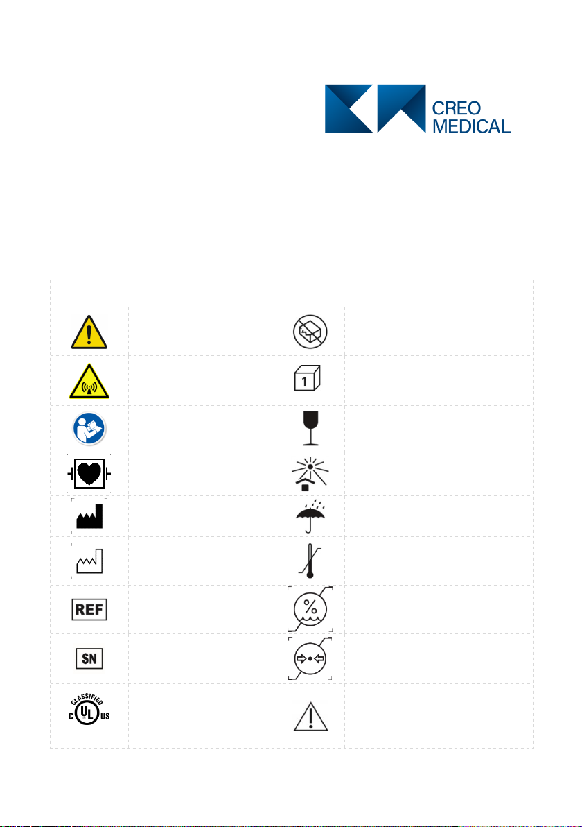
Explanations of symbols, wordings and definitions
Yellow symbol.
General Warning
Do not use if package is damaged
This device generates
non-ionizing radiation.
Do not remove the cover.
Packaging contains one unit
Blue symbol. Consult
Accompanying
Documents
Instrument can be broken or
damaged if not handled carefully
Defibrillator-Proof Type
CF Applied Part
Keep away from sunlight
Manufacturer
Keep dry
Date of Manufacture
Temperature limitation
Reference (model)
number
Humidity limitation
Serial number
Atmospheric pressure limitation
E464226
UL Classification Mark
(applicable only if this is
on the generator rear
panel)
Caution – Generator detected
fault or error when the red
indicator above this symbol is
illuminated
Proprietary & Confidential - Page 1 of 29 - Uncontrolled if Printed

Page 2 of 28
Explanations of symbols, wordings and definitions
Mains inlet power supply
fuses
Do not dispose of the
Electrosurgical Generator in
normal waste
Equipotentiality
2797
CE marking for the generator
CUT
Settings for cutting
function
COAG
Settings for coagulation function
Cutting Waveform Active
Coagulation Waveform Active
MR Unsafe
Medical Device
Output from the
Electrosurgical Generator
Do Not Use Blade to Open
Recycle
Warning, electricity
Consult instructions for
use
Authorised Representative in the
European Union
Transportation, this
symbol appears next to
the symbols indicating
environment limitations
during transportation
Storage, this symbol appears next
to the symbols indicating
environment limitations during
storage before and between uses
RS2
An example of a
proprietary surgical
accessory for use with
this Electrosurgical
Generator
Interface
Cable
A proprietary accessory cable that
connects the generator output
socket to the proximal end of the
surgical accessory
Non-ionizing radiation hazard from attached surgical accessory when
activated
Caution: US Federal law restricts this device to sale by or on the
order of a physician
Rx Only
(USA)
Proprietary & Confidential - Page 2 of 29 - Uncontrolled if Printed

Page 3 of 28
Safety Instructions
Biomedical Department Intended Use
This Biomedical User Manual is intended to provide information on safety and
performance checks that may be conducted on the Electrosurgical Generator. If the
immediate intended use is clinical endoscopy, the user is directed at the “Instructions
for Use, Electrosurgical Generator”.
The Electrosurgical Generator delivers radiofrequency (RF) electrosurgical and
microwave energy (MW) and is for use only with appropriate Creo Medical Ltd
accessories.
Microwave energy operation is outside the scope of Intended Use by the Biomed
Department.
This Biomedical User Manual is supplied with a Biomed Test Pack of cable
accessories. To avoid a risk of cross infection, these accessories are not for patient
use, must be retained by Biomedical personnel and not be introduced to the clinical
use environment.
Biomed User Qualification
The Biomedical operator of the Electrosurgical Generator must be a qualified
biomedical engineer with sufficient training in assessment of electrosurgical units.
Instructions for Biomedical Use
These Instructions for Biomedical Use contain essential information on how to
perform a limited range of safety and functional evaluations of the
Electrosurgical Generator. Before use, study this document thoroughly and
refer to it whenever in doubt. If you have any questions regarding these
Instructions for Use or the Electrosurgical Generator in general, contact Creo
Medical Ltd.
Please also refer to the manufacturer’s instructions for use that are supplied
with the footswitch.
Proprietary & Confidential - Page 3 of 29 - Uncontrolled if Printed

Page 4 of 28
Safety Instructions
Warnings
Indicate a hazardous situation which, if not avoided, may result in death or injury to the
operator.
Cautions
Indicate a hazardous situation which, if not avoided, may result in damage to the
Electrosurgical Generator, the Biomedical test equipment in use, or injury to the
operator.
Important Safety Warnings
Warnings
Do not activate the microwave (COAG, coagulation 5.8 GHz) output when the
Biomed Test Cables are connected.
Safe and effective operation of the Electrosurgical Generator is dependent not
only in the equipment design but also on factors that are directly under the
control of the user. The user should be qualified and experienced in operation
and functional assessments of electrosurgical units.
Use this Electrosurgical Generator only for purposes stated herein and in
accordance with these Biomedical Instructions for Use.
Using the Electrosurgical Generator and Creo Medical Ltd accessories
outside their intended use may result in a risk of serious injury to the operator.
Use this Electrosurgical Generator only with appropriate Creo Medical Ltd
Biomed Test Pack specified for use with this Electrosurgical Generator.
Use of non- Creo Medical Ltd accessories may lead to a risk of serious injury
to the operator.
Do not use the Electrosurgical Generator, a Biomed Interface Cable, a
Biomed RF Test Cable, or a Biomed Footswitch Cable any of these appears
to be damaged.
The Biomed Test Pack is validated for 20 use cycles. For further uses reorder
a replacement Pack (REF 7-PG1-301) to avoid risk of serious injury to the
operator.
Risk of RF burns - While the Electrosurgical Generator is temporarily in
Biomed Test mode, accessed via the entry of an access sequence of fascia
button presses as revealed in this IFU, there is the risk of RF burns from the
patient terminal if the Biomed Interface Cable is disconnected from the
Electrosurgical Generator.
Proprietary & Confidential - Page 4 of 29 - Uncontrolled if Printed

Page 5 of 28
Safety Instructions
If liquid is spilled on the Electrosurgical Generator or the connectors, including
the connectors of the Biomed Interface Cable, Biomed RF Test Cable or the
Biomed Footswitch cable, immediately cease operation, switch
Electrosurgical Generator off, and disconnect the Electrosurgical Generator at
the wall socket. If liquid is spilled on the Electrosurgical Generator or the
connectors, including the connectors of the Biomed Interface Cable, the
Biomed RF Test Cable or the Biomed Footswitch cable, there is a risk of
electrical or burn shock to the operator.
Do not activate the Electrosurgical Generator while the Biomed Test Cable
connectors or the connectors of the Biomed Interface Cable are in
unintentional contact with tissue or conductive surfaces other than associated
test equipment connections.
Do not open the cover of the Electrosurgical Generator or modify hardware or
software in any way. Servicing of the Electrosurgical Generator must only be
performed by Creo Medical Ltd personnel or their designated representative.
Modification or opening of the Electrosurgical Generator by unqualified
persons may result in electrical shock and will violate the warranty of the
Electrosurgical Generator.
To minimize possible failure of the Electrosurgical Generator, have the device
checked for safety and calibration once a year.
In the event of a malfunction or failure, immediately cease treatment and
switch the Electrosurgical Generator off using the On / Off Power switch on
the Rear Panel or by disconnecting the power supply cord from the
Electrosurgical Generator.
To avoid risk of electric shock the Electrosurgical Generator must be
connected via its ac power cord to mains supply with a protective earth.
USA only: Grounding reliability can only be achieved when the equipment
receptacle is mark “Hospital Grade”.
To avoid risk of fire, replace fuses only as marked.
The Electrosurgical Generator contains no user serviceable parts. To avoid
risk of electric shock and equipment malfunction do not remove any cover.
Modification or opening of the generator by unqualified persons may result in
electrical shock and will breach warranty of the generator.
Caution
Disconnecting the Biomed Test Cable from the Biomed Interface Cable while
cut or coagulation are activated poses the risk of burns when touching the
connector of the Biomed Interface Cable. Avoid touching the conductive
surfaces of the connectors of the Biomed Interface Cable at all times.
Proprietary & Confidential - Page 5 of 29 - Uncontrolled if Printed
Page 6 of 28
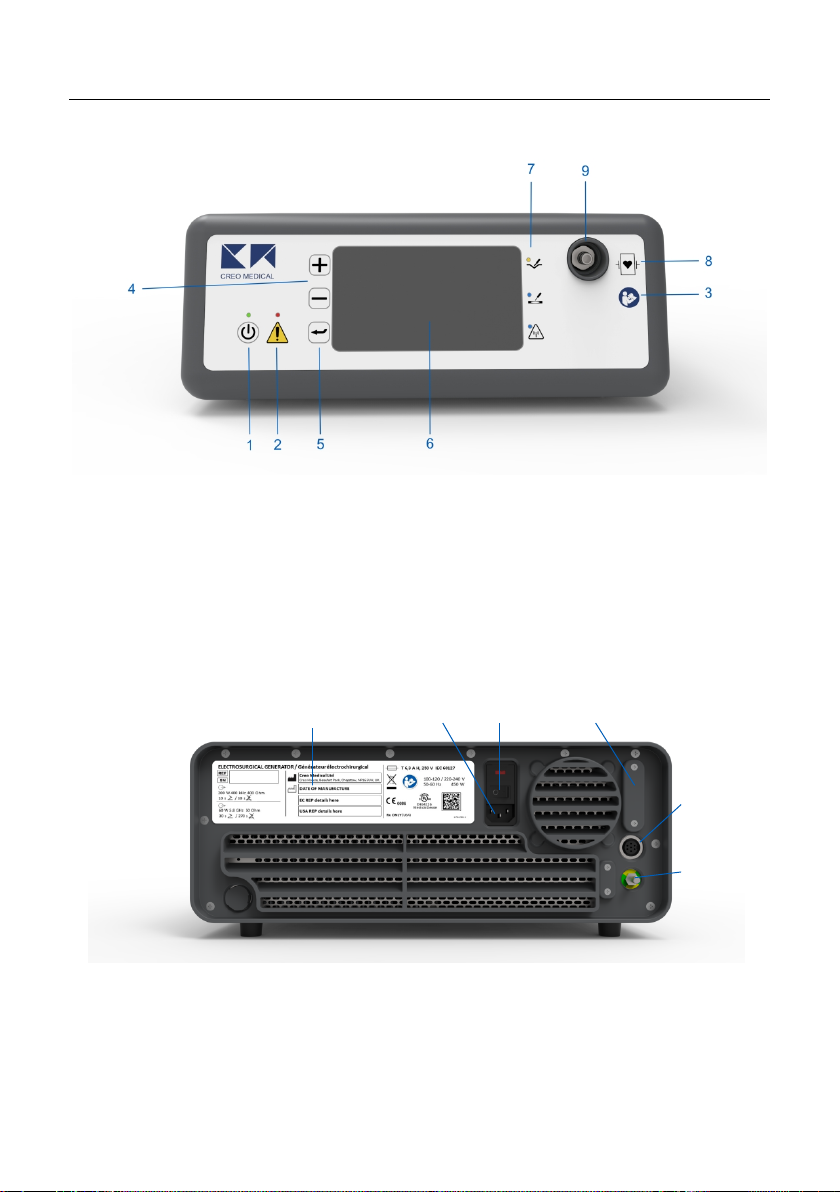
Device Description
Front Panel
1. On / Standby Button and
LED
2. Warning indicator
3. Symbol: Consult
Accompanying Documents
4. + / - Control Buttons
5. Menu control button
6. Display
7. Cut indicator LED (yellow)
Coagulation indicator LED (blue)
Microwave indicator LED (flashing blue)
8. Symbol Defibrillation-proof type CF
applied part
9. Output connection socket
Rear Panel
10. AC inlet
11. On / Off Power switch
12. Programming port
(service use only)
13. Footswitch connection
socket
14. Label with product name
and model number
15. Equipotential connection
14
10
11
12
13
15
Proprietary & Confidential - Page 6 of 29 - Uncontrolled if Printed

Page 7 of 28
Biomed Generator Non-Clinical Use Accessories
Biomed Test Pack – REF 7-PG1-301
The Biomed Test Pack is necessary for some verification of patient RF treatment
output and detection of attachment of surgical accessories.
16. Biomed Footswitch Cable 2-PG1-187
17. Biomed Interface Cable 2-RS2-210
18. Biomed RF Test Cable 2-PG1-185
19. Biomed Test Pack shipping and
storage carton
20. Biomed Cables storage carton
21. Biomed Instructions for Use (this
document)
The two pedal and one button, clinical-use footswitch REF 7-PG1-132 is also required
to verify the footswitch function. This assembly is included in the initial generator
shipment system or is otherwise within the surgical suite if the generator is already in
clinical service. It is not included as part of the Biomed pack as part of the Biomed test
function is to verify operation of the clinical-use footswitch. Identification marking for the
clinical-use footswitch is at the proximal end of the footswitch cable. The Creo
Electrosurgical Generator is incompatible with other footswitch assemblies even if they
have similar connector styles.
Proprietary & Confidential - Page 7 of 29 - Uncontrolled if Printed

Page 8 of 28
Set-up
Warning
The Electrosurgical Generator must always be connected to an AC power
supply with a protective ground (earth). Do not connect the power supply cord
(also referred to as an AC power cord) if it appears damaged or
contaminated, if it has been modified, or if it does not meet the requirement
specified in the product specification table in this Biomed Instructions for Use,
as there is a risk of electrical shock to the patient or user.
Condensation may occur when the unit is moved from a cold area into an
area intended for its use. Allow the Electrosurgical Generator to acclimatize
before connecting the power supply cord and/or turning the Electrosurgical
Generator ON. Condensation in the Electrosurgical Generator may cause a
fault to occur if the Electrosurgical Generator is turned ON.
The Electrosurgical Generator weighs approx. 35 lbs (16 kg) and the weight is
not evenly distributed. Care should be taken when lifting the generator.
Caution
The Electrosurgical Generator may cause electrical interference with other
equipment. Operation of the Electrosurgical Generator may be affected
adversely due to interference from other equipment. If interference occurs:
• Increase the distance between the Electrosurgical Generator and the
suspected interfering equipment in order to reduce interference.
• Ensure that Electrosurgical Generator cables and connected Instruments
are kept as far away as possible from other equipment cables.
The Electrosurgical Generator, Instruments, accessories, footswitch, and their
connection cables should be positioned such that damage or accidental
activation is avoided and that they do not present a tripping hazard.
There must be clearance of at least 3.5 inches to the rear of the
Electrosurgical Generator to allow for room for footswitch cable, AC power
supply cord, and for exhausting of air from the Electrosurgical Generator.
The Electrosurgical Generator is equipped with internal cooling fans. The
cooling air intake is located on the underside of the Electrosurgical Generator
towards the front on the right-hand side when viewing the front of the
Electrosurgical Generator. Do not allow this area to be blocked.
The Electrosurgical Generator should be positioned on a flat, horizontal worktop or
suitable trolley such that the Front Panel is visible and the Display are easy to read;
controls are readily accessible; and Instruments can be connected for their intended
use.
The Electrosurgical Generator should always be positioned so that it is possible to
switch the unit off by using the On / Off Power switch (11) on the Rear Panel of the
Electrosurgical Generator or by disconnecting the AC power supply cord.
Before connecting the AC power supply cord ensure the On / Off Power switch (11)
marked ‘I’ and ‘O’ above the AC inlet (10) for the power supply cord on the Rear Panel
is set to the off position with the part of the switch marked ‘O’ pushed inwards.
Proprietary & Confidential - Page 8 of 29 - Uncontrolled if Printed

Page 9 of 28
Summary of Possible Biomed Verification Activities
The table below identifies all the tests that may be performed by the Biomed user. The
generator is initially provided from your Creo Medical Ltd representative in shipping
packaging validated to assure arrival of the generator in a condition that is operational
and safe for use.
However, after a period of use or where there may have been rough handling during
shipping it would be reasonable to perform the suite of system checks as detailed in
this document. In all cases where the acceptance criteria stated cannot be met, the
Creo Medical Ltd representative should be contacted.
By default, the generator performs a wide scope of over 200 self-checks from first
connection to mains power, switch from Standby to ON, and thereafter persistently
during operation.
Refer to the clinical use Instructions for Use for information on accessing the Additional
Settings menu if this is required, for example for alarm volume and display brightness
adjustments.
Biomed User Tests
Section
Number
When to Conduct Test
Biomed Activity
1
Initial receipt of equipment
from shipping courier or
periodic maintenance
checks
Inspection of generator and clinical use
footswitch
2
Initial receipt of equipment
from shipping courier or
periodic maintenance
checks
Verification of generator electrical safety
3
Language change
required
Generator user interface language
selection
3
Periodic maintenance
checks
Verification of operation of generator
fascia user interfaces
4
Periodic maintenance
checks
Verification of clinical use footswitch
operation
4
Periodic maintenance
checks
Verification of surgical accessory detection
5
Periodic maintenance
checks
Verification of maximum RF power
calibration
Proprietary & Confidential - Page 9 of 29 - Uncontrolled if Printed

Page 10 of 28
1. Inspection of Generator and Footswitch
Event
Biomed Action
Acceptance Criteria
Inspect the
transportation
container(s)
Container has not been breached or
damaged such that the product or
accessories may have been damaged or
exposed to contamination.
Exterior of container has not been
contaminated (e.g. with liquids).
Container has not been previously opened.
Initial receipt of
equipment from
shipping courier
Open the
transportation
container(s) and
inspect contents.
Contents are correctly in place within the
internal packaging and appear to be
complete, consistent with packing label
descriptions
Remove the
generator from
transportation
container(s) if
pertinent.
Inspect the
generator
Generator is
•Free from splits and cracks.
•Free from any other damage and from
contamination.
•Free from missing, insecurely affixed or
illegible labels.
•Is marked with reference number:
7-EMR-050 and has a (non-Biomed)
Instructions for Use document present
Remove
footswitch from
transportation
container(s), if
pertinent.
Inspect the
footswitch
Footswitch is
•Free from splits and cracks.
•Free from any other damage and from
contamination.
•Free from missing, insecurely affixed or
illegible labels.
•Is marked on its cable with reference
number: 7-PG1-132 and has OEM
Instructions for Use present
Initial Receipt of
Equipment from
shipping courier or
periodic maintenance
checks
Inspect the AC
power cord
The AC power cord is
•Free from splits and cracks.
•Free from dents and broken parts.
•Free from any other damage and from
contamination.
•Is appropriate to the country of
installation.
•Is marked as Hospital Grade for US
power cords
•Inspect and confirm the fuse rating is
as follows:
UK: 10 A (UK)
There are no fuses in the EU,
South Africa and US type power
cords.
Proprietary & Confidential - Page 10 of 29 - Uncontrolled if Printed

Page 11 of 28
2. Electrical Safety Verification
Event
Biomed Action
Acceptance Criteria
Connect the power cord between the
Safety Tester and the generator mains
inlet connector.
Measure earth bonding resistance
between the Safety Tester socket plug
earth pin and the equipotential
terminal of the generator.
Measured value over a
10 second interval is <
0.2 Ohm.
With the On / Off Power (11) switched
to On (‘1’ depressed)
Measure the touch current when
contacting the enclosure.
This is done by contacting the probe
attached to the safety tester onto the
equipotential terminal of the generator.
Measured value over a
10 second interval is <
100 µA
With the On / Off Power (11) switched
to On (‘1’ depressed)
Patient leakage.
Measure the touch current when
contacting the Output Connection
Socket.
Measured value over a
10 second interval is <
10 µA
Initial receipt of
equipment from
shipping courier or
periodic maintenance
checks
With the On / Off Power (11) switched
to On (‘1’ depressed)
Measure the earth leakage current.
The probe is not required for this test.
Measured value over a
10 second interval is
< 500 µA for territories
with supply voltages of
220 Vac of more or;
<300 µA for territories
with supply voltage of
120 Vac or less.
Guidance on test equipment selection:
Each generator is tested at 25 Amps for earth bonding continuity at time of
manufacture. Earth bonding testing current amplitudes in the Biomed setting are
according to local policies. For field checks Creo Medical Ltd employs the Rigel 288+
for the safety tests listed above.
Proprietary & Confidential - Page 11 of 29 - Uncontrolled if Printed

Page 12 of 28
3. Verification of User Interfaces
Language Selection and
Verification of Status Indicators, Character Display and Display Buttons
Event
Biomed Action
Acceptance Criteria
Display LED Function Test
Connect the generator to the
wall mains supply mains
supply; switch the On / Off
Power (11) switched to On (‘1’
depressed), and then press
the ON/Standby button (1).
Repeatedly cycle through start
up if required by operating the
ON/Standby button (1).
All LEDs illuminate during
power-up
Periodic maintenance
checks
Character Display Test
Connect the generator to the
wall mains supply mains
supply; switch the On / Off
Power (11) switched to On (‘1’
depressed), and then press
the ON/Standby button (1).
Repeatedly cycle through start
up if required by operating the
ON/Standby button (1).
Across two successive screens
the following are displayed:
•English alphabet (A-Z) in
UPPER CASE, in two font
sizes.
•Numbers (0-9) in two font
sizes.
•Characters “+-*/=” in one font
size.
•English alphabet (A-Z)
displayed in lower case in one
font size followed by
characters, for example:
Language change or
periodic maintenance
checks
Language Selection and
Display Buttons Test
During the character test
display sequence above press
the Menu Control Button (5) to
stop the start-up process at
the language selection list.
Verify the function of the + and
- Control Buttons (4) by
scrolling the highlight up and
down the languages list using
+ and the – Control Buttons.
Stop the highlight over the
language required for local
clinical use and confirm
selection by pressing the
Menu Control Button (5).
User is able to access the
language selection menu using
the Menu Control Button (5) and
can move the highlight up the
language list using the + Control
Button (4), and down the
language list using the – Control
Button (4).
The generator restarts with the
display set to the selected
language.
Note: If this test can be
performed the On / Standby
Button (1) is already proven to
functioning correctly as it is
required to start the generator.
Proprietary & Confidential - Page 12 of 29 - Uncontrolled if Printed

Page 13 of 28
4. Verification of User Interfaces
Verification of Clinical Footswitch Operation and Surgical Accessory Detection
Event
Biomed Action
Acceptance Criteria
Periodic
maintenance
checks
Connect the generator to the wall mains
supply mains supply; switch on at the rear
rocker switch (11).
Connect
the clinical use footswitch to the generator
Footswitch Connection Socket (13),
the Biomed Interface Cable to the Output
connection socket, and the
Biomed RF Test Cable to the distal end of
the Biomed Interface Cable
Blue and Yellow pedal test:
Switch the generator to standby for each
check.
Continuously press the footswitch pedal
under test while restarting the generator
using the ON/Standby button.
Once pedal tests are complete, at the
display message to “Confirm Attached
Instrument” the footswitch centre black
button can be tested by pressing it to
confirm the selected instrument on the
display
Surgical accessory detection can be
completed by confirming that disconnection
of the Biomed RF test cable from the distal
end of the Biomed Interface Cable.
The generator responds
with a message to
indicate that the pedal
pressed is stuck until
released by the Biomed
operator.
The display advances
beyond the “Confirm
Attached Instrument”
message.
The displayed message
changes to “Attach
Instrument When Ready
to Proceed”
Proprietary & Confidential - Page 13 of 29 - Uncontrolled if Printed

Page 14 of 28
5. Verification of RF Output
Maximum Power, Continuous RF Waveform and Audible Alarm Tone Verification
Overview:
This generator is verified for maximum RF capability making use of a Biomed access
code entered by pressing the appropriate sequence of + / - Control Buttons (4) followed
by the Menu Control Button (5). To prevent injury to patients, access to the Biomed test
waveform is limited to 300 seconds after each entry of the Biomed access code. The
generator can be restarted, and the code re-entered as many times as is needed to
complete the RF waveform verification.
Using the Biomed Test Pack cables to connect the generator to the Rigel Unitherm
Electrosurgical Analyzer, the generator load curve verification can be completed within
a single 300 second count down, assuming appropriate settings are used on the
electrosurgical analyzer.
Proprietary & Confidential - Page 14 of 29 - Uncontrolled if Printed

Page 15 of 28
Verification of RF Output
Figure 1: Rigel Uni-Therm Analyzer Settings for Automated RF Load Curve Sweep
Figure 2: Rigel Uni-Therm Biomed Footswitch Cable Connections
Figure 3: Rigel Uni-Therm Biomed RF Test Cable Connections
Proprietary & Confidential - Page 15 of 29 - Uncontrolled if Printed

Page 16 of 28
Verification of RF Output
Event
Biomed Action
Acceptance
Criteria
Periodic
maintenanc
e checks
1. Semi-automated RF load curve measurement:
Rigel Uni-Therm Analyzer configuration:
Connect the Biomed Footswitch Cable and the Biomed
RF Test Cable to the Rigel Uni-Therm Analyzer for
automated testing using the Uni-Therm internal load
resistance and measurement device (MD) as shown in
Figures 2 and 3.
2. Generator Preparation:
Connect the Biomed Footswitch cable to the generator
Footswitch connection socket (13); and the Biomed RF
Test Cable to the distal end of the Biomed Interface
Cable. Do not connect the Biomed Interface cable to the
Patient Output connection socket (9) yet.
3. Generator Power Up:
Connect the generator to the wall mains supply mains
supply; switch the On / Off Power (11) switched to On
(‘1’ depressed), and then press the ON/Standby button
(1).
4. Biomed Code Entry:
When the generator displays “Attach Instrument when
Ready to Proceed” enter the Biomed access code as
follows:
Press the + Control Button 2 times;
Press the – Control Button 4 times;
Press the + Control Button 6 times; and
Press the Menu Control Button 1 time.
If the code has been correctly identified the Biomed
menu will now be displayed. If the code is not
recognised press and hold the On / Standby Button (1)
to return to standby. Press the On / Standby Button a
second time to restart the generator and return to the
beginning of step 4.
5. Biomed Operation
Connect the Biomed Interface cable to the generator
Patient Output connection socket (9) and confirm Test
cable connection by pressing the Menu Control button
(5). Start automatic load testing on the Uni-Therm
Analyzer.
Measured
RF power at
each load
resistance
step is within
20% of the
values in
Figure 4, with
a maximum
peak voltage
of 460 V +/-
10%.
An audible
alarm tone
from the
generator
accompanies
each RF
activation by
the Uni-
Therm
analyser.
Proprietary & Confidential - Page 16 of 29 - Uncontrolled if Printed

Page 17 of 28
Testing the microwave power output
Servicing – risk of injury or death.
There are no user serviceable parts in the generator. Servicing should
be performed only by suitably qualified persons in accordance with
servicing information provided by the manufacturer.
Incorrect servicing may result in faulty operation of the device and
accessories and exposure to hazardous voltages and electrical
currents that can cause death
Testing the Microwave Power Output – Risk of arcing, sparking,
damage to equipment and burn injury.
Tests to confirm satisfactory microwave power output must only be
undertaken by a suitably qualified technician trained and experienced
in the testing of high-power microwave devices with access to suitable
equipment.
Failure to perform testing correctly and without suitable equipment
may result in damage to the generator or its accessories, damage to
other equipment, arcing and sparking and instantaneous burn injury
due to absorption of high-power microwave energy.
On no account should any wire, cable or other conductor be
connected to the generator output socket other than a coaxial cable
type that is suitably rated and has the appropriate connectors fitted to
it (or appropriate coaxial adaptors used). The connection of any
unsuitable wire or cable will result in microwave power being radiated
from the generator output, this may result in injury and/or damage or
inference with other equipment.
Caution
The RF output is active during microwave output testing – risk of
damage to equipment.
The RF output is pulsed for 5 ms every 1 s in order to detect
disconnection of a surgical instrument. This output will be present
during the microwave testing specified below. It is the responsibility to
ensure that the equipment connected is not at risk of damage from an
output of 120 Vrms at 400 kHz.
Testing must only be performed by an appropriately qualified engineer using
appropriate equipment and measurement techniques.
At maximum output setting the generator produces an output at 5,800 MHz (5.8 GHz)
at a power of nominally 62 W measured at the generator output socket. The output can
only be tested using equipment, cables and connections specified for operation at least
Proprietary & Confidential - Page 17 of 29 - Uncontrolled if Printed

Page 18 of 28
5.8 GHz frequency and an input power level at least equal to the maximum power
output of the generator. The following equipment is recommended:
Power meter Keysightmodel E4418B
Power sensor Keysightmodel E4412A
High power attenuator NARDA 769A-30
Test cable Available from Creo Medical
N-N type connector adaptor Available from Creo Medical
QN to N adaptor Available from Creo Medical
The test set-up is illustrated below.
To enable accurate power measurement, the combined attenuation of the test cable,
high power attenuator and connection adaptors must be known accurately at 5.8 GHz.
The combined attenuation should be entered into the power meter as an offset factor to
enable direct indication of the power output from the generator output socket.
Acceptance criteria are as follows.
Instrument
selected during
power-up
Instrument
output power
setting
Power at generator
output socket into
50 Ohm load
Test condition
COAG 4
25.0 W
COAG 6
37.0 W
COAG 8
50.0 W
COAG 9
56.0 W
Speedboat RS2
COAG 10
62.0 W
Measure at the end of 10 s
output activation period.
In accordance with IEC 60601-
2-6:2012, the measured output
shall be within +/-20 % of the
stated output power.
Proprietary & Confidential - Page 18 of 29 - Uncontrolled if Printed

Page 19 of 28
Specifications
For BIOMED RF and Microwave CAOG Waveforms refer to the PG1 Generator
IFU (2-PG1-906)
Figure 4: 200 W RF Load Curve Specification
Proprietary & Confidential - Page 19 of 29 - Uncontrolled if Printed

Page 20 of 28
Specifications
Product Specification Table
Classification Under IEC 60601-1 Concerning Electrical Protection -
Classification:
Class 1. A protective earth connection must be provided
Applied Part -
Classification to IEC 60601:2005
Type CF. This is Defibrillator Proof.
Environment for Operation
Ambient Temperature:
+10 °C to +30 °C (+50 °F to +86 °F)
Relative Humidity:
20 % to 90 % non-condensing
Altitude Operating:
≤2000 m (6,560 feet), 80 kPa to 106 kPa
Environment for Hospital/Clinic Storage -
Ambient Temperature:
+0 °C to +30 °C (+32 °F to +86 °F)
Relative Humidity:
*10 % to 90 % non-condensing – *20 % once unpacked
Altitude Operating:
69 kPa to 106 kPa
Environment for Transportation -
Ambient Temperature:
-20 °C to +55 °C (+14 °F to +131 °F)
Relative Humidity:
10 % to 90 % non-condensing
Atmospheric pressure
69 kPa to 106 kPa
Power supply cord -
Power supply cord
250 V, 10 A, 2 m long with IEC 60320-C13 type connector.
USA type UL and CSA Recognized
Power Requirements -
Supply Type:
Single phase AC.
Protective electrical ground:
Equipment is Class I.
A protective electrical ground connection must be provided.
AC Voltage Range
100-120 / 220-240 V
AC Frequency:
50-60 Hz
Power:
450 W
Inlet Fuses
T 6.3 A H 250 to IEC 127
Output, RF – (Bio Med Only)
Output Frequency
396.7 kHz +/-2.0 kHz
Power Capability:
200 W
Rated Load:
400 Ohm
Recommended Duty Cycle:
10 s ON, 30 s OFF, 1 hour
RF Crest Factor:
1.6 continuous to 3.7 pulsed
Maximum Voltage:
460 V peak
Output, RF – Treatment Mode
Output Frequency
396.7 kHz +/-2.0 kHz
Power Capability:
35 W (Max)
Rated Load:
400 Ohm
Recommended Duty Cycle:
10 s ON, 30 s OFF, 1 hour
RF Crest Factor:
1.6 continuous to 3.7 pulsed
Maximum Voltage:
460 V peak
Output, Microwave -
Output Frequency
5,800 MHz +/- 1 MHz
Power Capability:
62 W nominal maximum measured at the output socket
Rated Load:
50 Ohm
Duty Cycle:
Refer to duty cycle for operation with a particular surgical
instrument as stated in the surgical accessory IFU.
RF Crest Factor:
1.4 (output is a sine wave)
Software Release -
Software Version
The software version is displayed on the Electrosurgical
Generator following switch on from Standby
Physical -
Weight:
16 kg / 35 lb
Proprietary & Confidential - Page 20 of 29 - Uncontrolled if Printed
Other manuals for 7-EMR-050
2
Table of contents
Other Creo Medical Medical Equipment manuals

Popular Medical Equipment manuals by other brands


Getinge
Getinge Arjohuntleigh Nimbus 3 Professional Instructions for use

Mettler Electronics
Mettler Electronics Sonicator 730 Maintenance manual

Pressalit Care
Pressalit Care R1100 Mounting instruction

Denas MS
Denas MS DENAS-T operating manual

bort medical
bort medical ActiveColor quick guide

AccuVein
AccuVein AV400 user manual


