Cres Cor CGMH73A Manual

5925 Heisley Road • Mentor, OH 44060-1833
MOBILE
DECONTAMINATION FL-2424
Rev. 0 (7/21) Page 1 of 6
Phone: 440-350-1100 Ext: 268 • www.crescor-hs.com
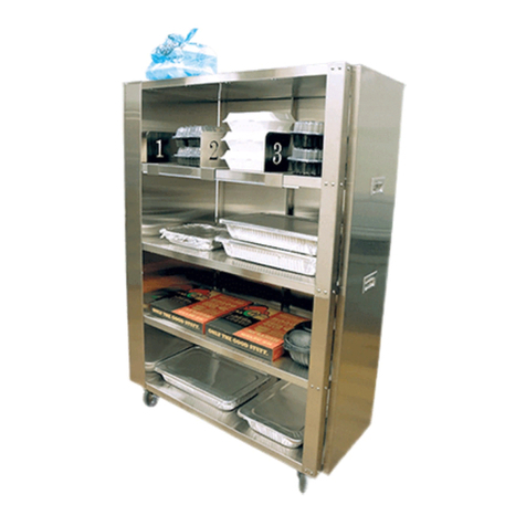
MOBILE DECONTAMINATION CABINET
OPERATING and MAINTENANCE INSTRUCTIONS Model #CGMH73A
Model no. Volts Watts Amps Hertz Phase NEMA
CGMH73A 120 2000 16.7 60 1 5-20P
HOW INSTALL UNIT:
1. Place cabinet on level oor, in well ventilated area.
2. Unpack and install parts for hangers or racks.
3. Plug cord into wall outlet.
FIRST TIME OPERATION:
1. Wipe the inside clean with detergent and hot water.
2. Fill water pan with 4 gallons of hot water.
HOW TO RUN THE DECONTAMINATION CYCLE:
1. Read all instructions before operating the Decontamination Cabinet.
2. Turn on the device by pressing the ON-OFF Switch. The switch light will come on.
3. The unit starts heating to the previous cycle settings. This is standby mode. The cycle light will be o.
The Temp Control will display “LOTPr” until 140°F is reached. Then the setpoint will be displayed.
4. To begin the decontamination cycle, press the “CYCLE” button. The display will show cycle “rcP01”
and the “CYCLE LIGHT” will be ashing. Cycle “rcP01” setpoints are 185°F at 65% humidity for
15 minutes.
5. Press the DIAL to set the cycle.
6. The unit will start preheating and the Temp Control will display “PrHEt” until the cabinet temperature setpoint is
reached. Then “PUSH StArt” will be displayed. Do not press the start button at this time.
7. The cycle conditions are preset by the factory and are locked to prevent modication and ensure repeatability.
8. Do not run the unit if the low water indicator light is ON. The light will turn o once water is relled.
9. Use the “DISPLAY” button to check for actual temperature and humidity as described under the
“Digital Control Notes” section on page 2.

5925 Heisley Road • Mentor, OH 44060-1833
MOBILE
DECONTAMINATION FL-2424
Rev. 0 (7/21) Page 2 of 6
Phone: 440-350-1100 Ext: 268 • www.crescor-hs.com
MOBILE DECONTAMINATION CABINET
OPERATING and MAINTENANCE INSTRUCTIONS Model #CGMH73A
NOTE: This cabinet operates with air temperature priority. Humidity will only start after cabinet is fully
preheated. If cold or room temp water is used, humidity build-up time will be longer.
10. When actual temperature and humidity are reached, ensure appropriate PPE is worn by the decontamination
personnel and place the items to decontaminate inside the decontamination system, close the door, and make sure
once again the low water indicator light is OFF.
11. Wait for the actual temperature and humidity to raise back to preset temperature and humidity settings on the
temperature and humidity displays. Use the “DISPLAY” button to check for actual temperature and humidity
values as described under the “Digital Control Notes” section below.
12. When the actual temperature and humidity are reached after loading, push the “START” button on the
temperature control. The “CYCLE” light will stop ashing and be on continuously, and the control will start
counting down.
13. If interrupted for any reason, the cycle should not be counted as complete and recommend repeating for ensuring
personnel safety. To re-start a cycle, press the “CANCEL” button, then press the “CYCLE” button and press the
“DIAL” to set the cycle.
14. Once the cycle is complete, the time displays zero and alarm is sounded. The unit will go into standby mode, and
the Temp Control display will toggle between the setpoint and the count-up time.
15. Open the door slowly allowing the steam to escape prior to opening fully before unloading the items.
16. Optional, press “CANCEL” to stop the count-up timer and turn unit o during unloading if perferred.
17. When done using the device, press the “CANCEL” button and press the ON/OFF switch. The switch light,
controls, blower and heaters will go o.
DIGITAL CONTROL NOTES:
• Press the “DISPLAY” button on the Temp Control to see the to see the actual temperature, cycle time, cycle
setting # (“rcP01”) and back to temperature set point. (When in PREHEAT, time and temperature setpoint will
not be displayed)
• Press the “DISPLAY” button on the Humidity Control to see the actual approximate relative humidity.
• Small letters in the upper right corners of the displays are:
• If the unit is switched o or power is lost to the unit when a cycle is running, the display and lights will ash
to indicate a power loss. To return to normal operation press cancel.
NOTE: When the low water light is on, the “A” humidity reading will not be accurate, and the water heater will not heat.
Temp Control: “S” = setpoint temperature
“A” = actual temperature
“t” = actual time
Humidity Control: “S” = setpoint humidity
“A” = approximate relative humidity
5925 Heisley Road • Mentor, OH 44060-1833
MOBILE
DECONTAMINATION FL-2424
Rev. 0 (7/21) Page 3 of 6
Phone: 440-350-1100 Ext: 268 • www.crescor-hs.com
MOBILE DECONTAMINATION CABINET
OPERATING and MAINTENANCE INSTRUCTIONS Model #CGMH73A
Delime or descale water pan parts as
required, to prevent damaging build-up.
WARRANTY COVERAGE MAY BE
AFFECTED WITHOUT PROPER
CLEANING.
Cleaning hints:
1. Wipe up spills as soon as possible.
2. Clean cabinet regularly to avoid heavy dirt build-up.
3. Make a test spot with cleaner.
4. Follow manufacturer’s directions on cleaner.
5. Do not mix cleaners.
6. Avoid drips and splashes.
7. Do not use “Cres Clean” on plastic parts or
labels.
HOW TO CLEAN THE UNIT:
Soil Cleaner Method
CABINET
Inside
and
Outside
(Stainless Steel)
ROUTINE CLEANING Soap, Ammonia, or mild
*detergent and water.
1. Sponge on with cloth.
2. Rinse with water.
3. Wipe dry.
STUBBORN SPOTS AND
STAINS
Mild abrasive made for
stainless steel.
1. Apply with damp sponge or cloth.
2. Rub lightly.
HARD WATER SPOTS
and SCALE Vinegar 1. Swab or wipe with cloth.
2. Rinse and dry.
*Mild detergents include soaps and non-abrasive cleaners.
NOTE: Gaskets are removable for cleaning.
BEFORE CLEANING CABINET:
1. Allow cabinet to cool.
2. Do NOT hose cabinet with water.
3. Do NOT get water on controls.
4. Do NOT use abrasives or harsh chemicals.
WARNING
DAILY MAINTENANCE:
WATER PAN
Drain, wipe and ll water pan daily. (Clear vinyl drain
hose is provided.)
1. Push hose onto drain nozzle under the cabinet base.
2. Turn knob to open the drain.
CABINET
1. Wipe the inside of the cabinet after daily use.
2. LEAVE DOORS SLIGHTLY OPEN TO FULLY
DRY INTERIOR.

Phone: 440-350-1100 Ext: 268 • www.crescor-hs.com
5925 Heisley Road • Mentor, OH 44060-1833
MOBILE
DECONTAMINATION FL-2424
Rev. 0 (7/21) Page 4 of 6
MOBILE DECONTAMINATION CABINET
OPERATING and MAINTENANCE INSTRUCTIONS Model #CGMH73A
WARNING: TO REDUCE THE RISK OF FIRE OR ELECTRIC SHOCK,
DO NOT REMOVE COVER (OR BACK)
NO USER-SERVICEABLE PARTS INSIDE
REPAIR SHOULD BE DONE BY AUTHORIZED SERVICE
PERSONNEL ONLY
RISK OF FIRE OR ELECTRIC SHOCK
DO NOT OPEN
WARNING
TROUBLE-SHOOTING CHART:
FAILURE: POSSIBLE CAUSE:
1. Switch light or control display does NOT
light up.
1a. Circuit breaker/fuse to wall outlet is blown
1b. Cord is unplugged from wall outlet.
1c. Switch is “OFF.”
1d. Switch or control defective.
2. Unit gets too hot or will not shut o. 2a. Relay or control defective.
UNPLUG UNIT FROM WALL OUTLET.
3. Unit does not heat. 3. Defective heater, relay, blower or control.
4. No humidity 4a. Low water
4b. Air temperature set too high.
4c. Defective heater, relay or control.
Controller (Thermostats) Error codes:
err 00 - Temperature probe defective
err 01 - Water ll time out

5925 Heisley Road • Mentor, OH 44060-1833
MOBILE
DECONTAMINATION FL-2424
Rev. 0 (7/21) Page 5 of 6
Phone: 440-350-1100 Ext: 268 • www.crescor-hs.com
MOBILE DECONTAMINATION CABINET
OPERATING and MAINTENANCE INSTRUCTIONS Model #CGMH73A
REPLACEMENT PARTS:
120V 208V 240V
Blower Kit 0769-180-SS-K 0769-182-SS-K 0769-182-SS-K
Heater Kit, Air 2000W 0811-022-K 0811-185-K 0811-023-K
Heater Kit, Water 1850W 0811-271 0811-278 0811-271
High Limit (water pan) 0848-060 0848-060 0848-060
High Limit - 400°F 0848-033 0848-033 0848-033
Power Cord 2000W 0810-065-12-K 0810-039-07 0810-039-07
Relay, Solid State 0857-136 0857-136 0857-136
Switch, Power 0808-125 0808-125 0808-125
Thermostat Control (Hot)
0848-092-41-CGMH-K 0848-092-41-CGMH-K 0848-092-41-CGMH-K
Thermostat Control (Humidity)
0848-092-05-CGMH-K 0848-092-05-CGMH-K 0848-092-05-CGMH-K
Thermostat Probe 0848-091-K 0848-091-K 0848-091-K
Terminal Block 0852-119 0852-119 0852-119
Transformer 0769-197 0769-197 0769-197
Vent Fan 0769-165 0769-174 0769-174
Water Pan Assembly 0756-037 0756-042 0756-037
Door, Complete (Stainless Steel) 73 1221-579-K
Door, Gasket (Stainless Steel) 73 0861-185-K
Door Hinge 0519-074-K
Door Latch 1006-122-01-K
Door Handle 0911-111
Handle, Side Pull 0911-087
Casters, 5” 0569-306-K
Casters, 5” w/brake 0569-306-BK
Angles (Stainless Steel) 0689-138
Wire Rack 1170-241
Clear Drip Pan 1017-058
Post 0696-315
Hanger Support 6153-085

Phone: 440-350-1100 Ext: 268 • www.crescor-hs.com
5925 Heisley Road • Mentor, OH 44060-1833
MOBILE
DECONTAMINATION FL-2424
Rev. 0 (7/21) Page 6 of 6
MOBILE DECONTAMINATION CABINET
OPERATING and MAINTENANCE INSTRUCTIONS Model #CGMH73A
VENT
FAN
POWER SWITCH
(REAR VIEW)
BLOWER
MOTOR
*MUST HAVE THERMAL GREASE
OR THERMAL PAD INSTALLED
BETWEEN RELAYS AND
MOUNTING SURFACES
SOLID STATE RELAY 2
WATER HEATER
L1 T1
A2(-)
A1(+)
t°
RENAU CONTROL
*LOCKWASHER AND
NUT (OR DOUBLE
NUTS) IS REQUIRED
TO HOLD GROUND
TERMINAL TO
GROUND STUD
AIR HEATER
HIGH LIMIT 400F
SOLID STATE RELAY 1
AIR HEATER
L1 T1
A2(-)
A1(+)
RENAU CONTROL
WATER HEATER
HIGH LIMIT 300F
t°
WATER
PROBE
AIR
PROBE
LOWER
FLOAT SWITCH
VENT
FAN
*PROBE WIRES RUN
DOWN OPPOSITE
SIDE FRAME RAIL
AS OTHER WATER
PAN WIRES
TB1
TRANSFORMER
2
1
4
3
1
2
3
4
5
6
5
6
8
7
7
8
10
9
910
11 12
11
12
13
13
14
14 15
16
17
18
17 18
19
20
19
20
21 22
21
22
23
24
23 24
25
25
26
26 27
28
28
OPTIONAL
DISCARD
WIRES 1
AND 2.
REPLACE
WITH
WIRES 41,
42, 43,
44 AND
WIRE AS
SHOWN:
41, 42 TO
TB1
43, 44 TO
POWER
SWITCH
41 42
43 44
N
N
L
L
45
46 47
45
46
47
AIR TEMP
LOOKING AT REAR
HUMIDITY
LOOKING AT REAR
TRANSFORMER WIRING 240V
G
FUSES
3A 3A
16
15
14
13
12
11
10
9
8
7
6
5
4
3
2
1
K3 K1 K2
P1 16
15
14
13
12
11
10
9
8
7
6
5
4
3
2
1
K3 K1 K2
P1
GREY/RED
RED/YELLOW
BROWN/BROWN
WHITE/WHITE
BLACK/BLACK
BLUE/ORANGE
PURPLE/BLUE
YELLOW/GREY
WIRE COLORS: TRIAD/HAMMOND
BROWN/BROWN
WHITE/WHITE
BLACK/BLACK
BLUE/ORANGE
(TO TERMINAL BLOCK)
WIRING DIAGRAM:
Table of contents
Other Cres Cor Heated Shelf manuals