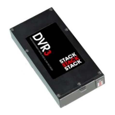
Stack ST8380 User manual

Part No.. ST542081-005
ST8380 Digital Video Recorder
Users Guide


STACK Digital Video Recorder
Users Guide i
Preface
Congratulations
Thank you for choosing the Stack Digital Video Recorder. This
solid-state recorder will give you many opportunities to make
video recordings in all kinds of harsh environments where
ordinary video recorders cannot be used.
Stack ® is a registered trademark of Stack Limited.
Information in this publication is subject to change without notice
and does not represent a commitment on the part of Stack Limited.
No responsibility is accepted for error or omission.
Copyright © 2005 Stack Limited

Preface STACK Digital Video Recorder
ii Users Guide
Related products from Stack
If you need information about other Stack products, these can be
obtained from Stack or from your local Stack dealer. Products
available from Stack include:
Synchronised Video Systems
Video Overlay Systems
DataPro Display and Analysis Software
Display and Data Logging Systems
Data Logging Systems
Radio Telemetry Systems
Intelligent Tachometers
Action Replay Tachometers
Performance Analysers
Speedometers
Boost Gauges
Analogue Sensors
Digital Sensors
Who to contact in case of difficulty
Stack and its approved Technical Agents provide a comprehensive
help service to assist with your enquiries. Contact your local Stack
branch or Technical Agent, a list of whom can be found on the
Stack web-sites.
United Kingdom Telephone Numbers:
Sales: 01869 240404
Tech Support: 01869 240420
Fax: 01869 245500
Email: [email protected]
Web site: www.stackltd.com
United States Telephone Numbers:
Sales: 888-867-5183
Fax: 888-364-2609
Email: [email protected]
Web site: www.stackinc.com

STACK Digital Video Recorder
Users Guide iii
Contents
Preface i
Related products from Stack ii
Who to contact in case of difficulty ii
Chapter 1 - Introduction 1
Chapter 2 - Essential User Information 3
Standard Components 3
Optional Components 3
Video Standard 4
Deleting Files 4
Using a New Removable Flash Disk 4
Playing a Recording 4
Before Making a Recording 5
Chapter 3 - Installation 6
Standard Wiring Harnesses 7
Video Overlay Wiring Harnesses 10
Chapter 4 - Operation 11
To make a recording: 11
To play a recording: 12
Operation with a new Flash Disk 14
Formatting a Flash Disk 14
Deleting Files 15
Corrupted Flash Disks 15
Chapter 5 - Flash Memory Cards 17
Chapter 6 - Configuration 18
PC Connection 18
Re-Scan 19
Lock Config 19

Contents STACK Digital Video Recorder
iv Users Guide
Manuf. Defaults 20
System Information 21
Record Set-up 22
Record Control 24
Record When Closed 24
Record Start / Record Stop (not currently available) 24
Triggered Recording 25
No Re-Trigger 25
Re-Trigger on Going Active 25
Re-Trigger while Active 26
Triggered Record Notes 26
Power Control 26
On-screen Display 27
Date and Time 28
Chapter 7 - Video and Data Systems 29
Synchronised Video Logger Systems 29
Video Overlay Systems 29
Manual recording status control 30
Recording Lamp 30
Recommended Vehicle System Power connections 31
Chapter 8 - Troubleshooting 32
Chapter 9 - Specifications 34
General 34
Appendix A - Mounting Template 37
Appendix B - Wiring Harness Diagrams 39
Standard Input Harness (ST918067) 39
S-Video Input Harness (ST918069) 39
DVR to V/VS Module Harness (ST900103) 40
System Harness (ST918066) 41
Power / Control Harness (ST918070) 41
Monitor / Configuration Harness (ST918068) 41
Returned Goods Procedure 42

STACK Digital Video Recorder Introduction
Users Guide 1
Chapter 1 - Introduction
The Stack Digital Video Recorder (DVR) is a compact, solid-state,
digital video recorder designed specifically for use in harsh
environments, where a standard video recorder or digital video
recorder could not operate.
The unit is housed in a rugged, waterproof enclosure containing no
moving parts making it ideal for use in harsh environments, such as
exposure to continual shock and vibration over extended periods as
well as extreme climate conditions and temperatures. The system
is DC powered and has optional audio inputs at microphone or line
level.
Typical Digital Video Recorder Application
Originally introduced to complement our award winning range of
motorsport products, the DVR can be applied to a much broader
spectrum of mobile engineering applications where protection
from a harsh environment is required.
The DVR can be supplied with products from our own range of
data display or data acquisition systems, including a video kit
incorporating a bullet CCD camera, and even a full Synchronised
Video or Video Overlay Data Acquisition System. Alternatively
the DVR can be supplied as a stand-alone, harsh environment
Digital Video Recorder for use with an existing video system.

Introduction STACK Digital Video Recorder
2 Users Guide
The DVR utilises broadcast standard MPEG-2 video compression
to record high quality Real-time video and audio to a PC Flash
Disk. This incorporates the ability to burn the date and time on to
the recorded video. Once a recording has been made, the Flash
Disk may be removed and played on a PC or laptop using a
standard media player application. Recordings may also be
archived to DVD using standard DVD burning software.

STACK Digital Video Recorder Essential User Information
Users Guide 3
Chapter 2 - Essential User Information
Please read the important information in this chapter before using
the Stack Digital Video Recorder (DVR).
Standard Components
Digital Video Recorders are supplied with the following standard
components:
Quantity Description
1 Digital Video Recorder (DVR)
(ST8380-NTSC or ST8380-PAL)
1 System Harness (ST918066 & ST918070)
1 Input Harness (ST918067)
1 Monitor Harness (ST918068)
1 Record Switch
1 Recording Status Lamp
Optional Components
DVRs may be supplied with the following optional components:
Quantity Description
1 DVR to VS Harness (ST900103)
replaces both Input and System Harnesses
1 S-Video Harness (ST918069)
replaces Input Harness
1 Bullet Camera & Microphone Kit
(ST8390 PAL or ST8391 NTSC)
Flash Disk

Essential User Information STACK Digital Video Recorder
4 Users Guide
Video Standard
The DVR is configured by default either for the NTSC or PAL
video standards depending on the intended country of use. If the
equipment you have uses the other video standard (eg, the DVR is
configured for NTSC but your equipment is PAL), you must
reconfigure the DVR as described on page 212.
Only NTSC and PAL are currently supported.
Deleting Files
Deleting files on the removable Flash Disk / PCMCIA Card does
not recover disk space. Only a reformat will recover space on the
Flash Disk. A Quick Format is sufficient, see page 14. Once a
recording has been made which you intend to keep, transfer the file
to your PC’s hard drive and then perform a reformat.
For the remainder of this guide the use of the term “Flash Disk”
shall be used to include a PCMCIA Card device too.
Using a New Removable Flash Disk
The DVR will only operate with a Flash Disk formatted with a
FAT32 (File Allocation Table) File System. Before using a new
disk, check its File System by inserting it into a PC running
Windows XP and display the disk properties by right clicking the
disk icon in “My Computer”. If supplied as FAT16, reformat to
FAT32, see page 14.
Playing a Recording
The files produced by the DVR are fully MPEG-2 compliant.
They may be played directly from the card by inserting it into a PC
with a suitable PCMCIA slot / adapter. However, better replay
results are usually obtained by transferring the file to the PC’s hard
drive, see page 12.

STACK Digital Video Recorder Essential User Information
Users Guide 5
Before Making a Recording
Before a recording session, if possible, clear the disk by performing
a reformat so that maximum disk space is available. A reformat can
only be achieved using a PC running Windows XP. Right-click on
the disk icon in “My Computer” and select “Format”. Ensure the
“File system” is set to “FAT32”, choose the “Quick Format” option
and then click “Start”.
Ensure any useful recordings have been archived before reformat.
Status
LED
Flash Card Slot
Card Eject Button
Door Catch

Installation STACK Digital Video Recorder
6 Users Guide
Chapter 3 - Installation
Before installing the DVR, take a few moments to plan the
installation. First identify all the components which came with your
system. You may like to perform a dry run by connecting the
components together to get a feel for how the final installation will
be accomplished.
Input
M
onitor
System
Connectors
Status LED
Water-tight Door
Eject Button
Door Catch Flash Card
(shown emerging)
The Stack Digital Video Recorder
Now, identify a suitable location for the DVR. It can be mounted
in any orientation but, when looking for a location, please bear in
mind that there must be approximately 50mm clearance for the
wiring harnesses at the back of the unit to ensure that the cables
will not be bent too sharply. There must also be enough space to
remove the Flash Card at the front. The module can be mounted
by various means including using double-sided tape or Velcro™.
A rigid mounting can be made to a suitable bracket using the six
M3 tapped holes in its underside, see Appendix A for dimensions.

STACK Digital Video Recorder Installation
Users Guide 7
Standard Wiring Harnesses
Once a mounting position has been determined, the components
should be connected using the wiring harnesses supplied. The figure
below shows the standard electrical connections to the unit. If you
are using the DVR with a Stack Video Overlay system, you should
have received specific wiring harnesses for that system. The
differences are described at the end of this chapter. Please contact
your Stack distributor if you need different wiring harnesses.
The wiring harnesses supplied by Stack are terminated with the most
commonly used connectors. If your equipment uses different
connectors, you will need to obtain appropriate adapters from a TV,
video or electronics supplier.
Input
(yellow)
System
(red)
Monitor
(blue)
Bullet Camera
Microphones
Record SwitchRecord Switch
Recording Lamp
Power 6.5 to 20 volts
PC Config Port
Monitor
Stack Digital
Video Recorder
Power supply for camera, mics etc
red
SW
RL
B
12V
CAM
V
A
CTL
left
right
white
Standard Electrical Connections

Installation STACK Digital Video Recorder
8 Users Guide
Connect a camera to the CAM plug on the Input Harness. If your
camera doesn’t have its own power supply, semi-regulated +12v
power can be taken from the two 2.1mm power plugs adjacent to the
BNC. The power plugs supply 12 volts or the supply voltage -2
volts, whichever is smallest, up to a maximum of 0.5 amps. If the
current required is greater than 0.5A, you must provide a separate
power supply.
As standard the composite (NTSC or PAL) input is active. If your
camera has a S-video connector, you will need to use the optional S-
video harness and then re-configure the DVR as described on
page 22.
Connect the Record Switch to the SW connector.
Connect a permanent DC supply of between 6.5 and 20 volts to the
Power (B+ and B-) connector. As a guide, the system draws
approximately 2.5 watts when recording. The current drawn will
increase as the voltage supplied becomes lower (eg 210 mA approx.
at 12 Volts, 390 mA approx. at 6.5 volts.) and with whatever other
equipment is connected using the two 2.1 power plugs. Whilst the
DVR is protected internally from over-voltage, you should provide a
3 amp fuse in the B+ connection to protect against short circuits in
your own wiring.
Important: Whilst the DVR will operate over a wide voltage range,
most cameras will only operate with power supplies of around 12
volts. Please check with your camera supplier.
A permanent power supply is required to ensure that recording
finishes cleanly when the Record Switch is turned off. If the supply
is obtained from a switched supply, eg, one controlled by a vehicle’s
ignition switch, the DVR could switch off before the recording has
finished, see page 15.
The following connections are optional:

STACK Digital Video Recorder Installation
Users Guide 9
If monophonic audio recording is required, connect a microphone
to the L (white) microphone input. An extra 2.1mm power
connector has been provided if that microphone needs to be
powered. Microphone gain can be adjusted by the PC
configuration software, see page 22.
If stereophonic audio recording is required, a second microphone
should be connected to the R (red) microphone input.
If audio recording is not required, it may be disabled to extend the
record time, see page 22.
The DVR provides a status output to indicate the system is
recording. Connect the optional Recording Status Lamp to the RL
connector. This is active-low (pull-down to ground) when
recording is OK and can be used to drive a LED with up to 50mA
max. (see wiring schematic below).
Never connect this to a light bulb since that will damage the
DVR’s internal circuits.
75Ω
B+ (DC Supply to DVR)
Current Limiting
Resistor, eg, 1KΩ
LED
Internal to
DVR
RO (Record OK)
GND (0 volt Ground)

Installation STACK Digital Video Recorder
10 Users Guide
A composite video output is provided for connection to an external
monitor which can be used to help align the camera, etc. The
video monitor output is the same as the input, with the addition of
the date and time display that is superimposed on the video
recording. Connect the yellow phono plug on the Monitor Harness
to video input on your monitor.
An audio monitor output is provided, which combines both the left
and right microphone inputs. This is used to aid the set-up of the
microphone levels, see page 22. Connect the white phono plug on
the Monitor Harness to the audio input on your monitor.
Video Overlay Wiring Harnesses
If connection of the DVR to a Stack Video Overlay system is
required, then a specific harness should be supplied for that
purpose. The Input Harness and the System Harness are replaced
by a single harness which allows direct connection between the
DVR and the Stack V/VS Module.
With this harness the signal from the camera is first directed to the
V/VS Module, which overlays vehicle data on to the picture,
before that signal is passed to the DVR.
Connect the various components as described above with the
addition of connecting the 15-way MIL connector to the V/VS
module and the 8-way connector to the Video Controller, see page
40.
The V/VS module and harness support composite video signals
only; S-Video is not supported.

STACK Digital Video Recorder Operation
Users Guide 11
Chapter 4 - Operation
To make a recording:
Check that video, power and a Record Switch are connected as
described in Chapter 3. Check that the Record Switch is set to the
open (off) position.
Apply DC power and the LED on the front panel will light showing
the status of the unit.
The status LED can only be seen when the water-tight door is open.
If the LED shows static green the system is ready to record.
If the LED is not static green, refer to the table below to find out the
DVR’s status.
If the Low Power Mode has been selected (see page 24), the LED will
light for approximately six seconds on power up before entering the
low current stand-by mode.
Important: Before making a recording, ensure there is enough disk
space available or preferably, reformat the Flash Disk. Disk space
may be checked on a PC or by making a trial recording and viewing
the DVR’s status LED, located inside the water-tight door (as
described below). Reformatting may be achieved using a PC. See
page 14 for more information regarding formatting options.
To start recording close the Record Switch. The LED will flash fast
red for approximately 1 second as it prepares to record. Once
recording, the LED will flash green for 3 seconds with a mark space
ratio showing the disk capacity remaining:
With an empty disk the LED will flash for approximately 3 seconds.
With 50% disk capacity remaining it will flash 1.5 sec on, 1.5 off.
With 10% remaining the LED will flash for 0.3 sec on, 2.7 sec off.
To stop recording, open (switch off) the Record Switch. The status
LED will revert to showing static green.
The disk may now be removed and placed into a PC with a suitable
PCMCIA card slot.

Operation STACK Digital Video Recorder
12 Users Guide
The table below shows the function of the DVR’s front panel
status LED. A green LED generally indicates the unit is
functioning correctly and a red LED indicates a fault or reset
condition.
LED Operation Description
Static green The Stack Digital Video Recorder is
ready to record (video and disk OK).
Flashing long red / short green
(with no gaps)
In stand-by (or unable to record) with
disk not present, faulty or full. Video
input OK.
Flashing long green / short red
(with no gaps)
In stand-by (or unable to record) with
video not present but disk OK.
Flashing equally green / red
(0.5s red / 0.5s green with no gaps)
Digital Video Recorder is under
external control of the PC
Configuration software.
Static red Unable to record as video and disk not
present, faulty or full. Or system fault.
Flashing green
External Recording Status Lamp also
illuminated
Recording OK. The longer the green
flash the greater the disk space
remaining. With an empty disk the
LED will flash for approx. 3 seconds.
With 50% disk capacity remaining the
LED will flash 1.5 sec on, 1.5 off.
With 10% remaining LED will flash for
0.3 sec on, 2.7 sec off.
Fast flashing green / red Recording but video is not present, ie,
audio only is being recorded.
Flashing red (fast) System reset / preparing to record or
disk format.
To play a recording:
To play DVR files with Windows Media Player, an MPEG-2
decoder must be installed on the PC. This should be present if a
DVD drive or player is installed. The decoder is NOT included
with the DVR Configuration Utility.
Other MPEG-2 compatible software players may be used.

STACK Digital Video Recorder Operation
Users Guide 13
Insert the Flash Disk into the PC’s PCMCIA slot. If a slot is
unavailable there are a number of USB to PC card adapters available
from PC vendors.
Allow the PC a few seconds to recognise the new disk and then run
“My Computer” or “Windows Explorer” to show the new drive.
Double click to display the disk contents.
My Computer / Removable Drive Digital Video Recorder Files
DVR video files are MPEG-2 compliant and filenames begin with
“FB” and have a “.MPG” extension. The files are given sequential
numbers starting from 0001. With a standard Windows
configuration, they will be seen as Windows Media Player files (see
above). To play, simply double-click the file and it will be
displayed.
Due to the slow read speed of Flash Disks, better results are usually
obtained by transferring the required file to the PC’s hard disk
before playing.
With an appropriate DVD burner and software, DVR files may also
be burnt onto DVD or Video CD for archiving without requiring
modification.

Operation STACK Digital Video Recorder
14 Users Guide
Operation with a new Flash Disk
Important: The DVR will only
operate with Flash Disks
formatted with a FAT32 (File
Allocation Table) File System.
Before using a new disk check its
File System by inserting into a
PC and displaying the disk
properties by right clicking the
disk icon in “My Computer”.
If the disk was supplied as
FAT16, reformat to FAT32 using
Windows XP’s format utility to
select the File System, see
Formatting a Flash Disk below.
Formatting a Flash Disk
Important: If using a new Flash
Disk, please ensure it has a
FAT32 File System. See
Operation with a new Flash Disk
above.
To format the disk using
Windows XP, right-click on the
disk icon in “My Computer” and
select “Format”. Ensure the “File
system” is set to “FAT32”,
choose the “Quick Format”
option and then click “Start”.
Table of contents
Other Stack DVR manuals
Popular DVR manuals by other brands
Vicon
Vicon Kollector Elite Installation & operation manual
Johnson Controls
Johnson Controls DVN 5000 Series Replacement instructions
Cantek
Cantek CW-AR705-4 Quick operation guide

CarVision
CarVision DVR 1CH SD Manual guide

Luxon Video
Luxon Video LIN104M Quick installation guide

Vook
Vook VDT2304ME quick start guide
