manuals.online logo
Brands
  1. Home
  2. •
  3. Brands
  4. •
  5. Crestron
  6. •
  7. Subwoofer
  8. •
  9. Crestron AIR IGS82T Dimensional drawing

Crestron AIR IGS82T Dimensional drawing

DO GUIDE
DO Check the Box
QTY PRODUCT PART NUM.
12 Screws N/A
12 Plugs N/A
4Screws N/A
1O-ring N/A
1Gasket N/A
5 Waterproof Wire Nuts N/A
DO Prepare the Site
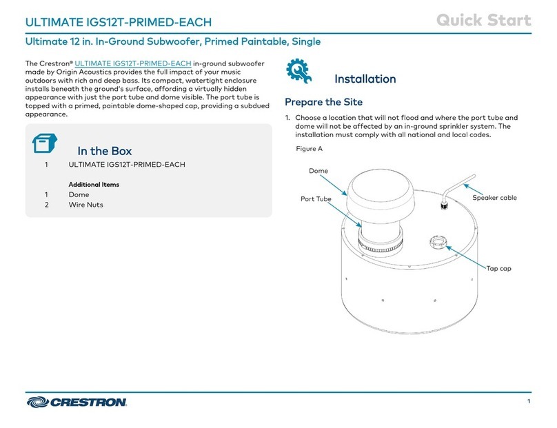
1. Dig a hole to bury the speaker. Refer to the illustration that follows for details. Choose a
location that will not ood with standing water and where the tube and cap assembly will
not be affected by an in-ground sprinkler system. The installation must comply with all
national and local codes.
NOTE: The hole must be deep enough to allow a 2 to 4 in (51 to 102 mm) layer of drainage
material (sand and gravel mix or other material approved by local codes) and position the
base of the speaker 13 to 17 in (330 to 432 mm) below ground level.
2. Run the cable from the audio source to a listed and acceptable junction box at the
speaker location while observing all local codes. If the cable is to be run underground, it is
advisable to run it through PVC pipe.
NOTE: The cable exiting the speaker is approximately 3 ft (1 m) long. Ensure that the
junction box is close enough for the speaker cable to reach inside.
AIR_IGS82T
Air®Dual 8” In-Ground Subwoofer
DO Assemble the Speaker
Refer to the illustration of the Crestron®Air®Dual 8” In-Ground Subwoofer that follows these
procedures for details on assembling the speaker:
1. Place the supplied O-ring in position on the top of the cover.
2. Using a Phillips screwdriver, attach the port tube and cap assembly to the top of the
cover with the four stainless steel screws (A) supplied. Apply even, hand-tight pressure to
compress the O-ring at the port tube base.
3. Ensure that the gasket is securely in position on the underside of the cover (the rounded side
toward the top of the cover). Place the cover on the speaker base assembly, and attach it
using the 12 screws (B) supplied. Torque the screws to a maximum of 19 ft-lbf (25.76 nm).
CAUTION: If the screws are over-torqued, they may strip the threads of the plastic
housing, and the water-tight integrity of the unit may be compromised.
NOTE: Do not insert the plugs (C) at this time.
2 to 4 in (51 to 102 mm)
Sand and Gravel Mix Per
Local Code for Drainage
13 to 17 in
(330 to 432 mm)
Ground Level
2 to 4 in (51 to 102 mm)
Sand and Gravel Mix Per
Local Code for Drainage
13 to 17 in
(330 to 432 mm)
Ground Level
Local Soil
Stainless Steel
Screws (A)
Screws (B)
Plugs (C)
O-ring
Port Tube and Cap Assembly
Cover
Base Assembly
Gasket
Audio Cable
DO GUIDE DOC. 7712A (2042353) 01.15
Specications subject to change without notice.
DO Install the Speaker
CAUTION: Do not connect the audio source to ac power until all speaker connections are
completed.
1. Use the supplied waterproof wire nuts to connect the speaker wires to the audio source
cable as shown in the hookup table and diagram below. Also, use the waterproof wire nuts
to terminate any loose (unconnected) wires.
NOTE: Verify that the speaker operates properly prior to placing it in the ground. During
this operation check, listen for sounds resembling air leaks around the speaker perimeter,
which would indicate that the cover is not tight enough in those areas. Recheck the screw
tightness in the areas where an air leak sound is heard.
2. Insert the 12 supplied plugs (labelled C in the assembly diagram on the previous page)
securely into the screw holes.
3. Place the speaker in the hole and cover it using the soil removed earlier.
DO Learn More
Visit the website for additional information.
Crestron Electronics
15 Volvo Drive, Rockleigh, NJ 07647
888.CRESTRON | www.crestron.com
As of the date of manufacture, the product has been tested and found to comply with specications for CE marking.
Federal Communications Commission (FCC) Compliance Statement
This device complies with part 15 of the FCC Rules. Operation is subject to the following conditions:
(1) This device may not cause harmful interference and (2) this device must accept any interference received, including interference
that may cause undesired operation.
Caution: Changes or modications not expressly approved by the manufacturer responsible for compliance could void the user’s
authority to operate the equipment.
Note: This equipment has been tested and found to comply with the limits for a Class B digital device, pursuant to part 15 of the
FCC Rules. These limits are designed to provide reasonable protection against harmful interference in a residential installation.
This equipment generates, uses and can radiate radio frequency energy and, if not installed and used in accordance with the
instructions, may cause harmful interference to radio communications. However, there is no guarantee that interference will not
occur in a particular installation.
If this equipment does cause harmful interference to radio or television reception, which can be determined by turning the
equipment off and on, the user is encouraged to try to correct the interference by one or more of the following measures:
• Reorient or relocate the receiving antenna
• Increase the separation between the equipment and receiver
• Connect the equipment into an outlet on a circuit different from that to which the receiver is connected
• Consult the dealer or an experienced radio/TV technician for help
Industry Canada (IC) Compliance Statement
CAN ICES-3(B)/NMB-3(B)
The specic patents that cover Crestron products are listed at patents.crestron.com. Product warranty can be found at www.crestron.com/warranty.
Crestron, the Crestron logo, and Air are either trademarks or registered trademarks of Crestron Electronics, Inc. in the United States and/or other countries. Other trademarks, registered
trademarks, and trade names may be used in this document to refer to either the entities claiming the marks and names or their products. Crestron disclaims any proprietary interest in the
marks and names of others. Crestron is not responsible for errors in typography or photography.
This document was written by the Technical Publications department at Crestron.
©2015 Crestron Electronics, Inc.
Input Type Input+ Input - Tie
Low Z, 8 Ohm Red Black N/A
70 V, 75W Purple Black Yellow to Red
70 V, 150 W Orange Black Yellow to Red
100 V, 75 W N/A N/A N/A
100 V, 150 W Purple Black Yellow to Red
Red
Yellow
Orange
Purple
Black
AIR_IGS82
Cable
Other Crestron Subwoofer manuals

Crestron REFERENCE OD4.1-4-S10-BRZ-T KIT User manual

Crestron

Crestron REFERENCE OD4.1-4-S10-BRZ-T KIT User manual

Crestron ASPIRE IWS82 User manual

Crestron

Crestron ASPIRE IWS82 User manual

Crestron ULTIMATE ASUB10-B-T-EACH User manual

Crestron

Crestron ULTIMATE ASUB10-B-T-EACH User manual

Crestron ULTIMATE ASUB10-B-T-EACH User manual

Crestron

Crestron ULTIMATE ASUB10-B-T-EACH User manual

Crestron ULTIMATE IGS12T-BRZ-T-EACH User manual

Crestron

Crestron ULTIMATE IGS12T-BRZ-T-EACH User manual

Crestron ULTIMATE IWS82-AW-W-T-EACH User manual

Crestron

Crestron ULTIMATE IWS82-AW-W-T-EACH User manual

Crestron ULTIMATE IGS12T-PRIMED-EACH User manual

Crestron

Crestron ULTIMATE IGS12T-PRIMED-EACH User manual

Crestron ULTIMATE ASUB10-B-T-EACH User manual

Crestron

Crestron ULTIMATE ASUB10-B-T-EACH User manual

Crestron ULTIMATE ICS8-AW-W-T-EACH User manual

Crestron

Crestron ULTIMATE ICS8-AW-W-T-EACH User manual

Crestron ULTIMATE ASUB10-B-T-EACH User manual

Crestron

Crestron ULTIMATE ASUB10-B-T-EACH User manual

Popular Subwoofer manuals by other brands

Mariner AQTB8 owner's manual

Mariner

Mariner AQTB8 owner's manual

JBL AM6212/95-WH Technical manual

JBL

JBL AM6212/95-WH Technical manual

Infinity PS410 owner's manual

Infinity

Infinity PS410 owner's manual

Klipsch Commercial All-Weather Series CA-800TSW Specifications

Klipsch

Klipsch Commercial All-Weather Series CA-800TSW Specifications

Kicker Soundgate SWRA406 manual

Kicker

Kicker Soundgate SWRA406 manual

Sony SA-SW5 user manual

Sony

Sony SA-SW5 user manual

Pyle Power PLPW6D manual

Pyle

Pyle Power PLPW6D manual

Wavemaster FUSION user manual

Wavemaster

Wavemaster FUSION user manual

Idea Bass-Reflex BASSO10i quick start guide

Idea

Idea Bass-Reflex BASSO10i quick start guide

Harman JBL Pasion 12SP manual

Harman

Harman JBL Pasion 12SP manual

JBL BASS550 Service manual

JBL

JBL BASS550 Service manual

D3 Media 4x4pro installation guide

D3 Media

D3 Media 4x4pro installation guide

Teufel US 5305/1 Technical description and operating instructions

Teufel

Teufel US 5305/1 Technical description and operating instructions

Polk Audio DX8 owner's manual

Polk Audio

Polk Audio DX8 owner's manual

Lanzar AQW10 user manual

Lanzar

Lanzar AQW10 user manual

Phase-Tech POWER LUX PL-10s owner's manual

Phase-Tech

Phase-Tech POWER LUX PL-10s owner's manual

Sony SA-WCT180 Service manual

Sony

Sony SA-WCT180 Service manual

Alpine PWD-X5 owner's manual

Alpine

Alpine PWD-X5 owner's manual

manuals.online logo
manuals.online logoBrands
  • About & Mission
  • Contact us
  • Privacy Policy
  • Terms and Conditions

Copyright 2025 Manuals.Online. All Rights Reserved.