Crestron REFERENCE OD4.1-4-S10-BRZ-T KIT User manual

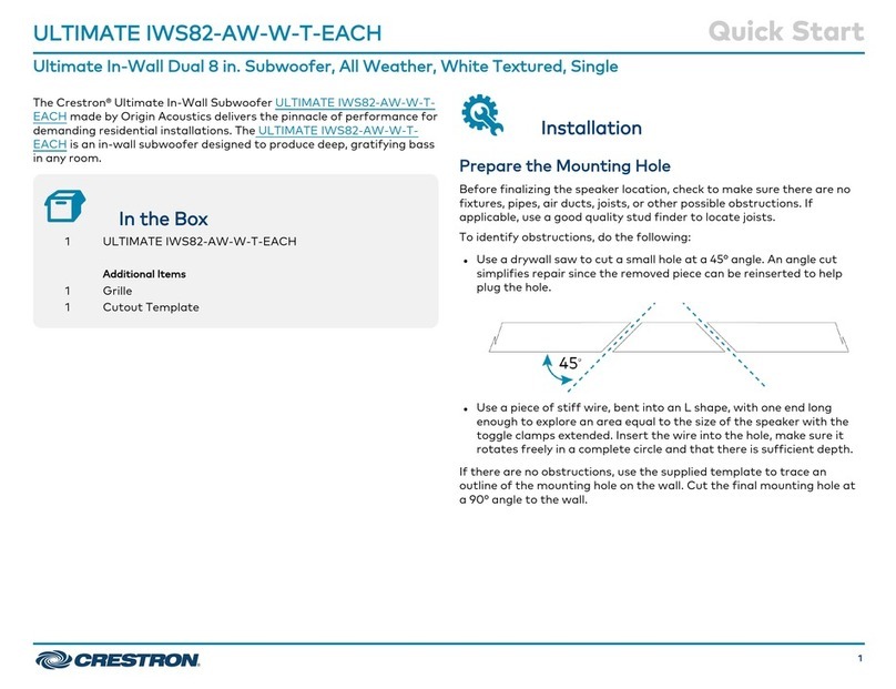
The Crestron® REFERENCE OD4.1-4-S10-BRZ-T KIT landscape solution
made by Origin Acoustics provides the full impact of your music
outdoors with tremendous coverage, excellent stereo imaging, and rich,
deep bass.
The 4.1 kit includes four weatherproof 2-way outdoor satellite speakers
and an in-ground subwoofer. The outdoor satellite speakers are
designed to be staked directly into the ground with the supplied ground
stakes.
NOTE: For individual speaker documentation, refer to REFERENCE
OD4-BRZ-T-EACH Quick Start (Doc. 9033).
In the Box
1 REFERENCE OD4.1-4-S10-BRZ-T KIT
Additional Items
4 Satellite speakers (6511866)
4 Ground stakes
1 In-ground subwoofer (4532740)
12 Wire nuts
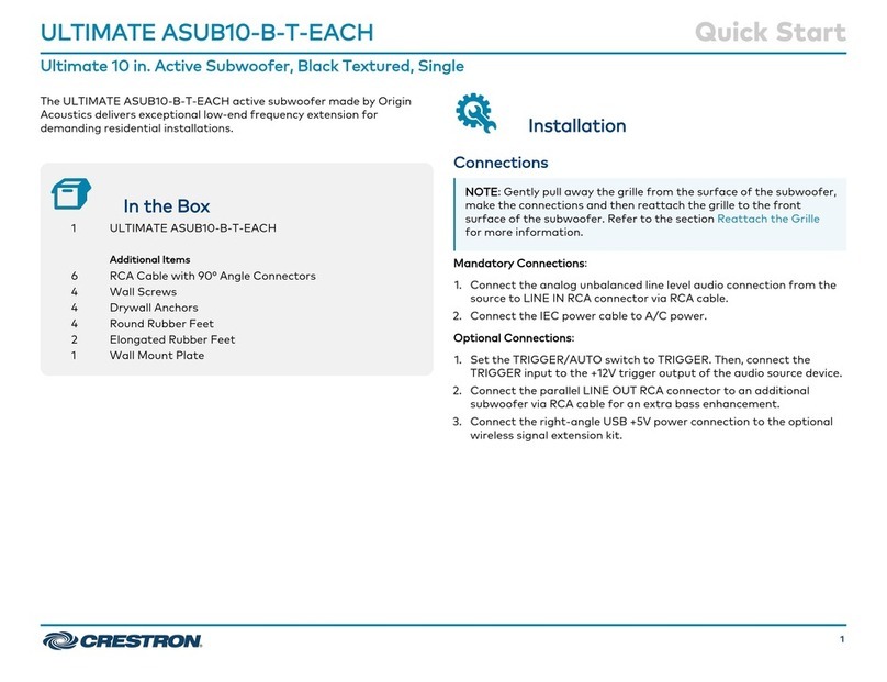
Installation
Recommended Speaker Wire
Crestron recommends using 12 to 16 gauge multistranded, direct-burial
outdoor speaker wire (not included) for installation, depending on the
overall distance from the amplifier (not included) to the further speaker
connection. Refer to the following chart for recommended wire gauge.
Distance from Amplifier to furthest speaker Recommended Wire Gauge (AWG)
0 - 100 ft(0 - 30 m) 16
50 – 150 ft (15 - 45 m) 14
Over 100 ft (30 m) 12
REFERENCE OD4.1-4-S10-BRZ-T KIT QuickStart
Reference 4.1 Landscape Solution, Bronze Textured, Four 4 in. Satellites, One 10 in. Subwoofer

1

Landscape Speaker Setup
Prior to connecting the speaker wire, fully plan out the locations of all
satellite speakers and the subwoofer. Place the subwoofer and satellite
speakers evenly around the landscape area. Refer to the following
diagrams for recommended speaker layouts.
Figure A - Satellite Speakers in Rectangular Configuration
Figure B - Satellite Speakers in Straight-line Configuration
2
REFERENCE OD4.1-4-S10-BRZ-T KIT QuickStart
Reference 4.1 Landscape Solution, Bronze Textured, Four 4 in. Satellites, One 10 in. Subwoofer

Subwoofer Placement
Select a location for the subwoofer near the middle of the satellite
speaker arrangement (see figures A and B). The subwoofer will provide
bass to approximately a 1500 sq ft area.
Subwoofer Installation
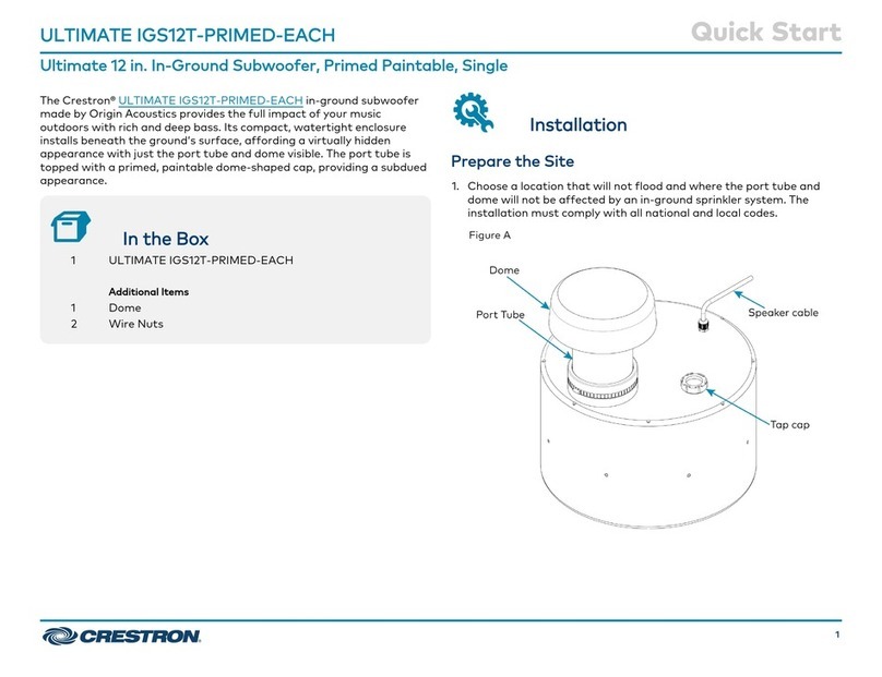
1. Once the layout of the subwoofer is determined, prepare to partially
bury the subwoofer in the desired location.
2. Dig a hole with the following minimum dimensions to bury the
subwoofer:
lDepth: 7.87-12.40 in. (200-315 mm)
lDiameter: 18 in. (457 mm)
3. At the bottom of the hole, prepare a level base for the subwoofer
free of voids and large rocks (see figure C).
NOTE: The hole must be deep enough to allow a layer of 2 to 4
in. (51 to 102 mm) play sand mixed with 0.5 cu. ft drainage
stone. Position the base of the speaker 6 to 8.5 in. (152 to 216
mm) below ground level.
Figure C - Prepare the Site for Subwoofer Installation
4. Place the subwoofer into the ground.
NOTE: Ensure that the vents are exposed and the top of the
subwoofer is about 4 in. (102 mm) above the ground level – do
not bury vents at ground level.
3
REFERENCE OD4.1-4-S10-BRZ-T KIT QuickStart
Reference 4.1 Landscape Solution, Bronze Textured, Four 4 in. Satellites, One 10 in. Subwoofer

Satellite Speaker Placement
Place the satellite speakers between 8 and 10 feet (2.4 to 3 meters)
apart for best coverage (see figures A and B). Consider that one
satellite speaker will provide sound to about 200 to 500 sq ft. The
speakers can be installed at ground level using stakes (included).
NOTE: The included stakes measure about 12.43 in. (316 mm) in
length. For longer stakes, use the SPKA-STAKE-OD-18 optional
accessory.
Satellite Speaker Installation
With the four satellite speakers in their desired locations, dig a 4 to 5 in.
(102-127 mm) deep trench to run the speaker wire (not included) from
the amplifier to each speaker. Ensure trenching and speaker wire usage
follow local codes.
Speaker Connections
1. Run the speaker cable (not included) through the trench from the
amplifier to the first speaker location (this can be a satellite speaker
or the subwoofer, depending on your speaker placement in relation to
the amplifier).
NOTE: When connecting the speaker wire to an amplifier located
indoors, ensure all indoor and outdoor connections follow local
codes.
2. Refer to the following application diagrams (see figures D and E) to
determine the appropriate wiring configuration. Then, connect the
speakers as described in steps 3 through 7.
Figure D - Satellite Speakers in a Rectangle Configuration
4
REFERENCE OD4.1-4-S10-BRZ-T KIT QuickStart
Reference 4.1 Landscape Solution, Bronze Textured, Four 4 in. Satellites, One 10 in. Subwoofer
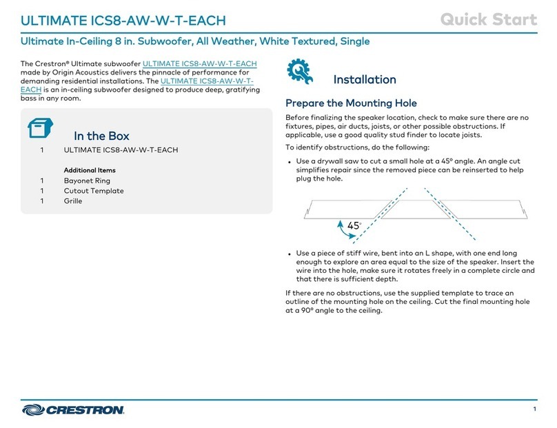
Figure E - Satellite Speakers in a Straight-line Configuration
3. At each speaker's location: Combine and twist all exposed positive
(+) leads together in a clockwise motion. Next, repeat this step for all
the exposed negative (-) leads.
4. Secure the three positive (+) leads together (lead from the amplifier,
hardwired speaker lead from the first speaker, and lead to the rest of
the speakers) using the wire nuts, ensuring that no copper is exposed
(see figure F). Repeat this step for all the negative (-) leads.
Figure F - Secure the Cables - Satellite Speaker
5
REFERENCE OD4.1-4-S10-BRZ-T KIT QuickStart
Reference 4.1 Landscape Solution, Bronze Textured, Four 4 in. Satellites, One 10 in. Subwoofer
NOTES:
lEach satellite speaker includes a hardwired direct-burial
speaker cable.
lMake sure that the positive cable is attached to the red
connection, and the negative cable is attached to the black
connection.
lBe sure not to let any stray ’+’ and ’-’ strands touch each
other. Touching strands will cause a short-circuit which could
damage the amplifier.
lEach REFERENCE OD4-BRZ-T-EACH speaker presents a 16
ohm load to the amplifier, and is designed to be wired in
parallel either with additional REFERENCE OD4-BRZ-T-EACH
speakers and/or with the subwoofer included in
theREFERENCE OD4.1-4-S10-BRZ-T KIT. These speakers are
also suitable replacements for the speakers in the
REFERENCE OD4.1-4-S10-BRZ-T KIT.
5. Repeat steps 3 to 4 for each successive speaker.
6. Connect the remainder of the speakers.
7. The subwoofer needs to be connected in the same manner as the
satellite speakers (see figure G).
NOTES:
lThe subwoofer includes a hardwired direct-burial speaker
cable.
lThe subwoofer has dual voice coils, one for the channel 1
and one for the channel 2, It is critical that the positive and
negative cables be connected correctly for both channels. If
either channel is connected incorrectly, no low-frequency
sound will be produced.
lMake sure that the white (+) and green (-) wires are used
for the channel 1 signal path and red (+) and black (-) for
the channel 2 signal path.
Figure G - Secure the Cables - Subwoofer
8. After all the speaker connections are completed as shown above,
connect the speaker cables to your amplifier.
6
REFERENCE OD4.1-4-S10-BRZ-T KIT QuickStart
Reference 4.1 Landscape Solution, Bronze Textured, Four 4 in. Satellites, One 10 in. Subwoofer
9. Once the wiring is completed, install the speakers as follows:
a. Drive the ground stake (included) into the ground.
lFor installation in soft soil: The stake can be installed
without excavating the soil. Push the stake down into the
soil.
lFor installation in hard soil: Dig a hole for the stake. Place
the stake in the hole with the top cylinder of the stake
above ground level. Hold the stake straight while backfilling
and compacting the soil.
10. Refill the wire trench and enjoy your new speakers.
7
REFERENCE OD4.1-4-S10-BRZ-T KIT QuickStart
Reference 4.1 Landscape Solution, Bronze Textured, Four 4 in. Satellites, One 10 in. Subwoofer
Visit the Product Page
Scan the QR code to visit the product page.
REFERENCE OD4.1-4-S10-BRZ-T KIT
http://www.crestron.com/model/6512253
Additional Information
Original Instructions
The U.S. English version of this document is the original instructions.
All other languages are a translation of the original instructions.
Crestron product development software is licensed to Crestron dealers and Crestron
Service Providers (CSPs) under a limited nonexclusive, nontransferable Software
Development Tools License Agreement. Crestron product operating system software is
licensed to Crestron dealers, CSPs, and end-users under a separate End-User License
Agreement. Both of these Agreements can be found on the Crestron website at
www.crestron.com/legal/software_license_agreement.
The product warranty can be found at www.crestron.com/warranty.
The specific patents that cover Crestron products are listed at
www.crestron.com/legal/patents.
Certain Crestron products contain open source software. For specific information, visit
www.crestron.com/opensource.
Crestron and the Crestron logo are either trademarks or registered trademarks of
Crestron Electronics, Inc. in the United States and/or other countries. Origin Acoustics is
either a trademark or registered trademark of Origin Acoustics, Inc. in the United States
and/or other countries. Other trademarks, registered trademarks, and trade names may
be used in this document to refer to either the entities claiming the marks and names or
their products. Crestron disclaims any proprietary interest in the marks and names of
others. Crestron is not responsible for errors in typography or photography.
©2022 Crestron Electronics, Inc.
Doc. 9034B
01/19/22
8
REFERENCE OD4.1-4-S10-BRZ-T KIT QuickStart
Reference 4.1 Landscape Solution, Bronze Textured, Four 4 in. Satellites, One 10 in. Subwoofer
Other manuals for REFERENCE OD4.1-4-S10-BRZ-T KIT
1
Table of contents
Other Crestron Subwoofer manuals

Crestron
Crestron ULTIMATE ICS8-AW-W-T-EACH User manual

Crestron
Crestron ULTIMATE ASUB10-B-T-EACH User manual

Crestron
Crestron ASPIRE IWS82 User manual

Crestron
Crestron AIR IGS82T Dimensional drawing

Crestron
Crestron ULTIMATE IGS12T-BRZ-T-EACH User manual

Crestron
Crestron ULTIMATE ASUB10-B-T-EACH User manual

Crestron
Crestron ULTIMATE ASUB10-B-T-EACH User manual

Crestron
Crestron ULTIMATE IGS12T-PRIMED-EACH User manual

Crestron
Crestron ULTIMATE ASUB10-B-T-EACH User manual

Crestron
Crestron ULTIMATE IWS82-AW-W-T-EACH User manual