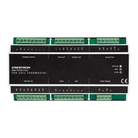
Modulated OP-CL 230 Vac Valve
This device is designed for use with a 2-pipe, 3-speed FCU with 230 Vac common open or
close valve.
In this case, the valve performs regulation in the ∆T vicinity of set point; the valve opens
and closes at the rate of its dened time, according to the graph below.
Periodically, the valve is forced to the fully open position to eliminate accumulated error.
Error annulation period is dened by Reset valve error interval parameter. The valve is
controlled using two relays (Stg 1 - open, Stg 2 - close).
The diagram of working compressor according to room temperature is shown in the graph
below.
T (˚
Sp-3∆T Sp+3∆TSp-2∆T Sp+2∆TSp-∆T Sp+∆TSpH SpC
100
Ymin
0
• SpH - Set point for heating
• SpC - Set point for cooling
• Y - Valve position (0% closed, 100% fully open)
• Ymin - Minimum position of valve when the set point is reached
• T - Room temperature
• ∆T - Step of temperature difference (∆T=N•0.5 °C, where N is a settable parameter)
• t - Time to valve reach full open or close position
NTC
1
Fan
1
CV
1
S
WS
WR
POWER SUPPLY:
230 Vac power input for
line, neutral, and earth
STAGE OUT:
230 Vac max power for open
and close control to the valve
FAN OUT:
230 Vac max fan power
in and fan control out
STATUS
NET
COM
DIN-TSTAT-FCU
TEMP SENSE
DIGITAL IN COM
VALVE OUTPOWER SUPPLY STAGE OUTFAN OUT
NET
L
L
L
L 1
FL
FM
FH
NC
L2
ST1
ST2
OP
24V
CL
24V
0-10
G
E
NC
N
N
N
CDI
DI3
CDI
TS1
G
TS2
G
DI0
CDI
DI1
CDI
DI2
Y
Z
G
EP
A
B
G
24
COM:
To the
room
controller
NET:
To the
control
system
TEMP SENSE:
From the
temperature
sensor
Spring-loaded 230 Vac Valve
This device is designed for use with a 2-pipe, 3-speed FCU with spring-loaded 230 Vac
valve.
In this case, the valve operates as an on and off valve. The valve value is calculated
according to room temperature, as shown in the graphs below. The valve is controlled using
one relay (Stg 1 - open).
The diagram of working compressor according to room temperature is shown in the graph
below.
t (time)
Sp
T* Ymin
0
0t (time)
100
valve %
t (time)
Sp
T* Ymin
0
0
100
valve %
• Sp - set point
• ∆T* Ymin - Temperature when the valve is open
NTC
1
Fan
1
CV
1
WS
WR
POWER SUPPLY:
230 Vac power input for
line, neutral, and earth
FAN OUT:
230 Vac max fan power
in and fan control out
STATUS
NET
COM
DIN-TSTAT-FCU
TEMP SENSE
DIGITAL IN COM
VALVE OUTPOWER SUPPLY STAGE OUTFAN OUT
NET
L
L
L
L 1
FL
FM
FH
NC
L2
ST1
ST2
OP
24V
CL
24V
0-10
G
E
NC
N
N
N
CDI
DI3
CDI
TS1
G
TS2
G
DI0
CDI
DI1
CDI
DI2
Y
Z
G
EP
A
B
G
24
STAGE OUT:
230 Vac max power for
open control to the valve
COM:
To the
room
NET:
To the
control
TEMP SENSE:
From the
temperature
1-2 Stage Direct-expansion System
This device is designed for use with a 3-speed, direct-expansion system with compressor
control - cooling only.
In this case, a compressor is controlled instead of a valve. The compressor state for stage
one and stage two is determined by the room temperature. The compressor is controlled
using two relays (Stg 1 – stage 1, Stg 2 – stage 2).
The diagram of working compressor according to room temperature is shown in the graph
below.
t
∆T
∆T/2
Sp
S1
S2
0
0
• Sp - set point
• ∆T - Step of temperature difference (∆T=N•0.5, where N is a settable parameter)
• S2 - Stage 2 on
• S1 - Stage 1 on
NTC
1
Fan
1
AS
AR
POWER SUPPLY:
230 Vac power input for
line, neutral, and earth
FAN OUT:
230 Vac max fan power
in and fan control out
STATUS
NET
COM
DIN-TSTAT-FCU
TEMP SENSE
DIGITAL IN COM
VALVE OUTPOWER SUPPLY STAGE OUTFAN OUT
NET
L
L
L
L 1
FL
FM
FH
NC
L2
ST1
ST2
OP
24V
CL
24V
0-10
G
E
NC
N
N
N
CDI
DI3
CDI
TS1
G
TS2
G
DI0
CDI
DI1
CDI
DI2
Y
Z
G
EP
A
B
G
24
STAGE OUT:
230 Vac max power for Stage 1 and
Stage 2 control to the compressor
COM:
To the
room
NET:
To the
control
TEMP SENSE:
From the
temperature
Fan Speed Control
For all congurations, the fan speed shifts to low, medium, and high based on room
temperature. When a room temperature reaches its set point, the fan either shuts down or
the fan turns on low.
If the fan speed is forced, the fan constantly runs at the selected speed.
High
Medium
Low
T (˚C)
Sp-3∆T Sp+3∆T
Sp-2∆T
• SpH - Set point for heating
• SpC - Set point for cooling
• T - Room temperature
• ∆T - Step of temperature difference (∆T=N•0.5 °C, N is settable parameter)
Water Temperature
The second TEMP SENSE input can be used for water temperature measurement.
Parameters can be set to determine the minimum temperature difference between the
ambient temperature of the room and the water temperature for the FCU to effectively
perform its function. When cooling is performed, the device ensures that the water in the
system is adequately cooler than the ambient temperature. When heating is performed,
the device ensures that the water in the system is adequately warmer than the ambient
temperature. If the water temperature is not adequate, the fan is turned off and the valve
is fully opens.
Digital Inputs
The device has four digital inputs that act as alarm inputs. Alarm inputs are used for
accepting contacts from a window or door sensor, condensation canister full sensor, PIR
sensor, etc.
If using the digital inputs, congure them using the settable parameters. When a digital
input is activated, it blocks the device outputs. For example, fan speed will be set to 0 and
valve will be shut.
There are three parameters available for each digital input:
• Enable - alarm is used or unused
• Polarity - alarm active state
• Delay - time from alarm activation to blocking the outputs
DIGITAL IN:
From the window
switch, door switch, or
occupancy sensor
POWER SUPPLY:
Power input for line,
neutral, and earth
STATUS
NET
COM
DIN-TSTAT-FCU
TEMP SENSE
DIGITAL IN COM
VALVE OUTPOWER SUPPLY STAGE OUTFAN OUT
NET
L
L
L
L 1
FL
FM
FH
NC
L2
ST1
ST2
OP
24V
CL
24V
0-10
G
E
NC
N
N
N
CDI
DI3
CDI
TS1
G
TS2
G
DI0
CDI
DI1
CDI
DI2
Y
Z
G
EP
A
B
G
24
COM:
To the
room
NET:
To the
control
Commission the System
The DIN-TSTAT-FCU is set up and commissioned using DIN-TSTAT-FCU Conguration
Tool. Refer to the DIN-TSTAT-FCU Setup and Commissioning Guide (Doc. 8207) at
www.crestron.com/manuals for more information.
As of the date of manufacture, the product has been tested and found to comply with specications for
CE marking.
The product warranty can be found at www.crestron.com/warranty.
The specic patents that cover Crestron products are listed at www.crestron.com/legal/patents.
Certain Crestron products contain open source software. For specic information, please visit
www.crestron.com/opensource.
Crestron and the Crestron logo are either trademarks or registered trademarks of Crestron Electronics,
Inc. in the United States and/or other countries. Other trademarks, registered trademarks, and trade
names may be used in this document to refer to either the entities claiming the marks and names or their
products. Crestron disclaims any proprietary interest in the marks and names of others. Crestron is not
responsible for errors in typography or photography.
This document was written by the Technical Publications department at Crestron.
©2017 Crestron Electronics, Inc.
Crestron Electronics, Inc. Installation Guide - DOC. 8203B
15 Volvo Drive Rockleigh, NJ 07647 (2048940)
Tel: 888.CRESTRON 08.17
Fax: 201.767.7576 Specications subject to
www.crestron.com change without notice.
