Crestron C2N-TTVFM TV & FM Radio Tuner
Operations Guide - DOC. 6266A TV & FM Radio Tuner: C2N-TTVFM •3
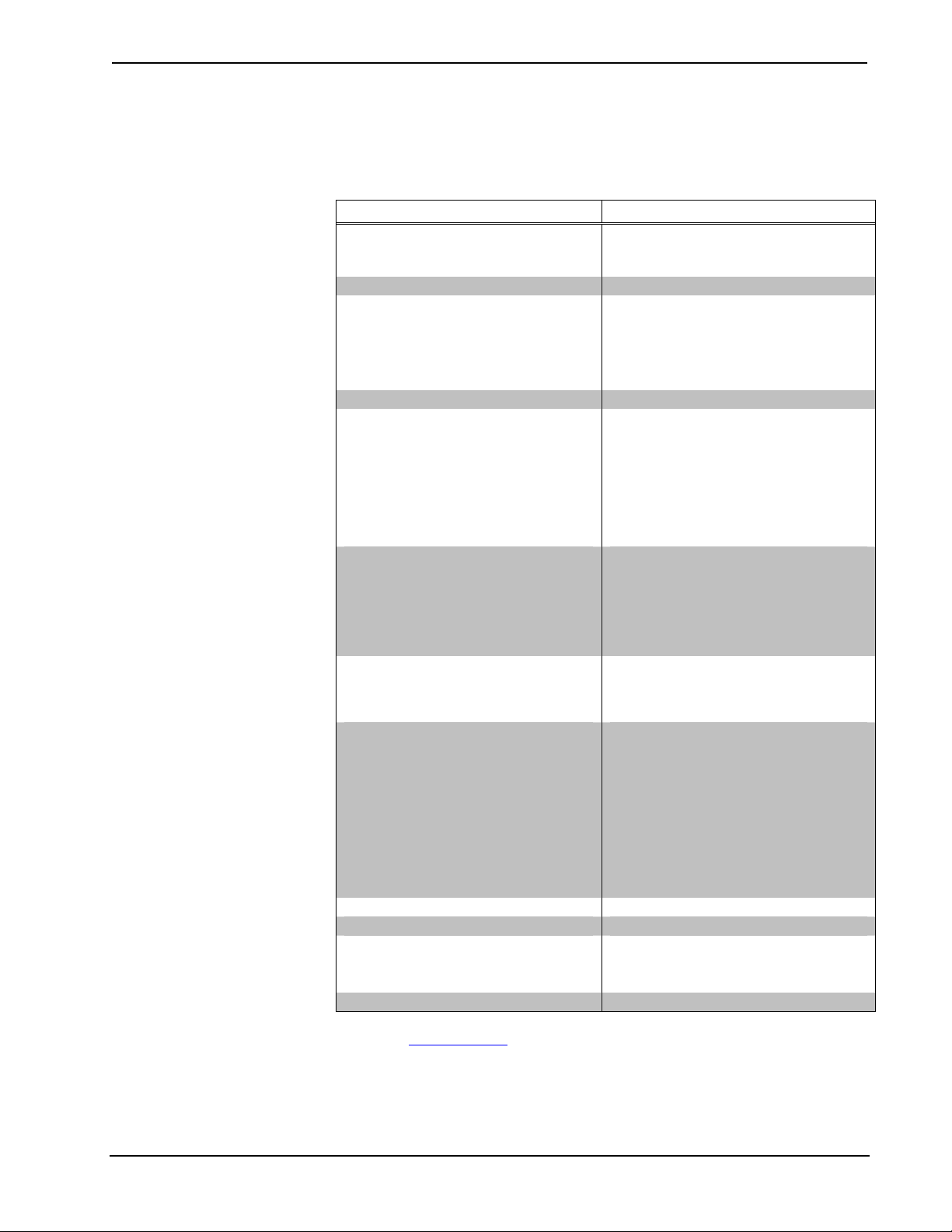
Specifications
The following table summarizes the specifications for the C2N-TTVFM Tuner.
Specifications of the C2N-
TTVFM
SPECIFICATION DETAILS
Power Requirements
TV/FM Tuner only
TV/FM Tuner plus AMWX Tuner
8.0 Watts (0.3 Amp @ 24 VDC)
16.0 Watts (0.66 Amp @ 24 VDC)
Default Net ID 47
Control System Update Files 1, 2, 3
2-Series Control System
CNMSX-AV/PRO
CNRACKX/-DP
CEN/CN-TVAV
Version 2.004.CUZ or later
Version 5.12.63X.UPZ or later
Version 5.12.63W.UPZ or later
Version 5.12.63V.UPZ or later
C2N-
TTVFM
Firmware C2N-
TTVFM
.1.12.upg or later
TV Tuner
Frequency Range
Off-air TV channels
CATV cable channels
Stereo separation
THD
Sensitivity
Video output level
SAP
55 MHz to 802 MHz
2 to 69
2 to 125
35 dB
0.2% @ 1 kHz
-20 dBmV to +20 dBmV
1 Vp-p @ 75 Ohms
Secondary Audio Program
FM Tuner
Frequency range
Usable sensitivity
S/N ratio
IF rejection
AM rejection
Stereo separation
87.5 MHz to 108 MHz
11 dBf mono; 60 dBf stereo
64 dB @ 65 dBf mono; 56 dB @ 65 dBf stereo
100 dB
55 dB
27 dB
Audio Output
Maximum output
Output impedance
Minimum load
1 Vrms balanced
200 Ohms balanced, <100 Ohms single ended
600 Ohms balanced
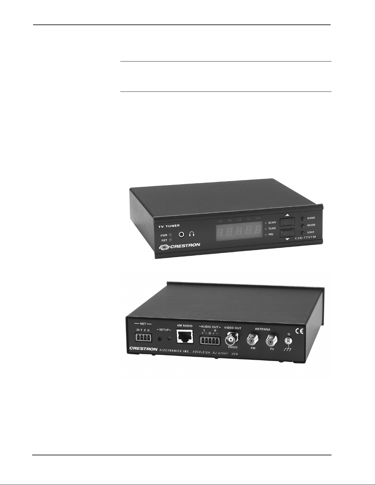
Ports/Connectors
NET
AM RADIO
AUDIO OUT
VIDEO OUT
FM ANT
TV ANT
Four-pin mini-terminal block connector for
Cresnet®interface (24, Y, Z, G)
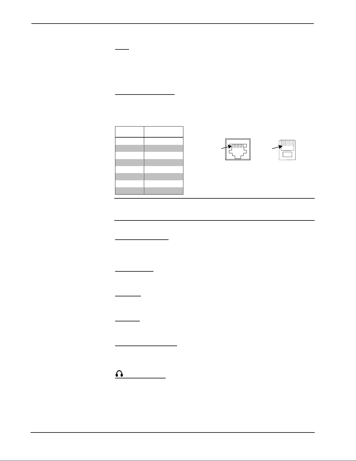
RJ-45 for link (up to 500 feet) to AM/Weather
band tuner
Five-pin mini-terminal block for balanced line-
level stereo
BNC Female for composite video
F-Type coaxial connector for FM antenna input
F-Type coaxial connector for TV antenna input
Environmental temperature 32° to 122°F (0° to 50°C)
Humidity 10% to 90% RH (non-condensing)
Dimensions Height: 1.80 in (4.57 cm)
Width: 7.07 in (17.96 cm)
Depth: 6.85 in (17.40 cm)
Weight 1.86 lb (0.84 kg)
1 The latest versions can be obtained from the Downloads | Software Updates section of the Crestron
website (www.crestron.com). Refer to following NOTE.
2 Crestron 2-Series control systems include the AV2 and PRO2. Consult the latest Crestron Product
Catalog for a complete list of 2-Series control systems.
3 Filenames for CNX and ST-CP update files have a UPZ extension. Files on the website may be .zip
or self-extracting .exe files containing the .cuz or .upz file. All can be obtained from the Downloads