CrimeStopper CS-872 User manual

CS-872 / SP-202 and SP-302
KEYLESS ENTRY and ALARM SYSTEM
INSTALLATIONINSTRUCTIONS
INTRODUCTION
CONGRATULATIONS onyour choiceofaRemoteKeyless Entryand AlarmSystembyCrimestopper
SecurityProductsInc.Thisbookletcontainstheinformationnecessaryforinstalling,using,and maintaining
youralarmsystem.If anyquestionsarise,contactyourinstallationdealer or Crimestopper SecurityProducts
Inc.at the TechSupportnumberbelow.
*IMPORTANTINFORMATION:
Thissystemcan beconfigured tooperateasaKeyless Entry,1-WayAlarmor 2-WayPaging AlarmSystem.
The typeofsystemisoption selectable(option #17). When selecting keyless entry,all featuresoperateexcept
the alarmtriggersaredisabled.
Thisinstallationbookisdesignedfortheinstallerorindividualwithanexistingunderstandingof
automotiveelectricalsystems,alongwiththeabilitytotestandconnect wiresforproperoperation.
Toeaseinstallation,wesuggestthat youREADTHISMANUALbeforebeginningyourinstallation.
ThisbookisprovidedasaGENERALGUIDLINEand theinformationcontainedhereinmaydifferfrom
yourvehicle.
TECH SUPPORT
Mon-Fri 8:00 AM-4:30 PMPacificTime
(800)998-6880
REV. 10-2012
Thisdevice complies withFCC Rules part 15. Operationissubject to
thefollowingtwo conditions: 1) Thisdevicemay not cause interference,
and(2) thisdevice must accept anyinterferencethat may be received,
includinginterferencethat maycauseundesired operation.The
manufacturer isnot responsiblefor anyradioor TV interferencecaused
by unauthorizedmodificationto thisequipment. Suchmodification
could void theuser's authority to operate the equipment.

2
TABLEOF CONTENTS
InstallationCautions&Warnings..…….……………………………….……………………………………….……2
ControlModule&ComponentMounting……………...……………………..……………………….…….…..…..3
LEDandValet ProgrammingButton………………………………………………………………………………….3
Wiring………………………………………………………………………..…………………..………….….…….….4-5
StarterKill Wiring………………………………………………………………………..…………………..…………..6
PowerDoorLockWiring……………………………………………………….………………………….…...….…7-8
PassengerDoorUnlock Wiring………………...……………………………….………………………….…...….…9
TransmitterProgramming………………………………………………………………………………….…………10
OptionProgramming…………………………………………….…….………………….…….…………...….…11-15
SHOCK SENSORWiring…….…………….………….….…..…………………………………………………….…16
WiringDiagram..…………………………………………………..……………………………..……………..………17
AntennaDiagram..………………………………………………..……………………………..……………..………18
DataPortDiagram…………………………………………………………………………………………………..…19
INSTALLATIONCAUTIONS&WARNINGS
BEFOREBEGINNING,checkall vehiclemanufacturercautionsandwarningsregardingelectricalservice(AIR
BAGS, ABS BRAKES, ENGINECOMPUTERS, BATTERYetc.).
WE RECOMMEND theuseofaVOLT/OHMMETERtotest and verifywiringcircuits. Testlightsorilluminated
probescancausedamagetoon-boardcomputer or enginemanagementsystems.
DO NOTexceedmaximumoutputratings.
WE RECOMMEND that theMAINSYSTEMFUSE beREMOVED before jumpstarting,using abattery
charger,or changing the battery. Avoltagesurgeorhigh boost conditioncoulddamage alarmcircuits.
DONOTROUTEANYWIRINGTHATMAYBECOMEENTANGLED withbrake,andgaspedals,steering
column,or anyothermovingpartsinthevehicle.

3
CONTROL MODULE&COMPONENT MOUNTING
DONOTMountthecontrolmoduleintheenginecompartmentorwherethewiring harness can
becomeentangledwithmovingpartssuchasbrake/gas/clutchpedals,orthesteeringcolumn! The
alarmcontrolmoduleshouldbe mounted inaconcealedlocation.The Placementofthemodulewill affectthe
distancefromwhichtheremotetransmittercancontroltheunit.Theantennawire shouldberoutedawayfrom
anymetalifpossible.Donotalter thelengthofthe antennawireor routeitwithotherwires.Donotground
theantennawire.Fastenthemoduletoabracketorwireharness usingthecabletiesprovided.Underdash
Mounting:If youarelocatingthe controlunitunderdash,mountitashigh aspossible,noteasilylocated byan
intruder.Driver’sSideUnder dashmountingprovidesaneasylocation for wiringmostofthe system’s
connections;howeverthisisacommonlocationforanintrudertocheckforan alarmafterbreakingintothe
vehicle.
SIREN: Mountthe siren under thehood toaninner fender-well,wheel-well,or other bodysurfacewiththe
openendfacing downward.Runthe red siren wirethrough the firewall using arubbergrommet. Groundthe
sirensblackwire tometalnearthe sirenoryoucan useoneof thesiren’smountingscrewsforaground.
LED:2PINPLUG
MounttheblueLEDinavisiblelocationon thedashboard or console. TheLEDisused asaVALET/
PROGRAMMING indicator anditwillalsoFLASHfor useassecuritydeterrentwhenthesystemisArmed.
Valet/ Programming Button:2PINPLUG(REQUIREDFORPROGRAMMING &LEARNING REMOTES)
Thisswitchisused for programming features,transmitters,valetmode,andtooverridetheoptionalstarter
disable(ifinstalled)intheeventofanon-operatingremotecontrol.MounttheValet/Override/Programpush-
button inahidden butaccessiblelocation.ItisREQUIREDforemergencydisarm,programming featuresand
enteringorexitingValetMode.
VALET/PROGRAMSWITCH
STATUSLED

4
WIRING
GREENWIRE:(-)NEGATIVE DOORTRIGGER
Identifythe wire thatreadsgroundwhen anydoorisopen and12voltswhen all doorsare closed.Some
vehiclesmayhaveisolateddoortriggers.Inthiscaseyoumayneed torun additionalwiresfromother doors
or godirectlytothewirethattriggersthe vehicle’sinteriordomelight.Sometimesnewervehiclescontaina
separatebodycontrolmodule(BCM)where the doortriggercircuitcan belocated.Onevehiclewill not
requiretheuseof BOTHNegativeand Positivedoor triggerwires.
VIOLETWIRE:(+)POSITIVE DOORTRIGGER
SameastheGREENwire aboveexcept thiswireisusedforvehiclesthat showapositivevoltage (12volts)
whenthedoorisopenandagroundwhendoorsareclosedasinmanyFord,Lincoln,andMercuryvehicles.
BLACK WIRE:SYSTEMCHASSISGROUND
The BlackwireMUSTbe connectedtothe CHASSISMETALofthe vehicle.Scrapeawayanypaintor debris
fromtheconnection pointanduseastarwashertoensure agoodconnection.Keepthegroundwireshort.
YELLOWWIRE:IGNITIONSWITCHED“ON”AND “START”+12VOLTS
ConnecttoanIGNITIONwire(orfuseinthefusebox)thatshows+12Voltswhenthekeyisinboth“On”and
“Start”(WHENCRANKING)positions.
GRAYWIRE:(-)NEGATIVE AUXREMOTEOUTPUT1(Optional,may requirearelay)
Connecttothe Negativetrunkreleasecircuit ortotheactivationcircuit of anauxiliarymoduleordevice.If the
circuitrequires+12V,thenarelayisrequired.RELAYWIRING: ConnecttheGraywire toterminal85,connect
relayterminals86and 87to+12Vconstantpower.Connectterminal30 ofthe relaytothe+12Vpositive
device/circuittobe activated.
BLUEWIRE:(-) NEGATIVE HOOD/TRUNK TRIGGER(Optional)
Inputtriggerforagroundinghoodortrunkpinswitch.Connecttoexistinghoodandtrunkpinswitchesthat
readground when open.Ifnoexistingswitchesare available,install newpinswitchesifdesired.Note:DO
NOTmountnewpinswitchesinwater pathways.

5
WIRING
BLACK/WHITEWIRE:(-)NEGATIVE DOMELIGHTILLUMINATIONOUTPUT(Optional, requiresarelay)
Thiswireprovidesa(-)negativegroundwhenthe systemisdisarmedtoactivateavehiclesdomelightcircuit.
Werecommend the useofarelayforthisconnection.ConnectBlack/Whitetoterminal#85ofrelay. Connect
terminal#86tofused constant+12V.Connectterminal#87toa+12Vconstantorground sourcedepending
on the typeofdomelight circuit inthe vehicle. ConnectTerminal#30 tothe domelight circuit inthe vehicle.
BROWN/WHITEWIRE:(-) HORN PULSE / CHIRPOUTPUT(Optional, mayrequirearelay)
Connect totheNegativeHornTriggerwire usuallylocated near thesteeringcolumn.Ifthevehiclehorncircuit
requires+12V, thenarelayisrequired.
WHITE/REDWIRE:(-)OEMDISARMorAUX2OUTPUT(programmableoption#16)
Thiswire providesaGround pulsetodisarmthevehiclesFactoryAnti-Theft Systemwithunlock.Connectthis
wire tothevehicles' anti-theftdisarmwire.Thiswireissometimesfound coming off theDriver's door key
switchor atthe FactoryAnti-theft controlmodule.Thiswire canbe programmed for Aux2.Itconnectsthe
samewayasRemoteOutput1see GRAYWIREdescriptionabove.
BLUE/WHITEWIRE:(-) PassengerDoorUnlockOutput(Optional, mayrequirerelay)
Thiswireactivateswhentheunlockbutton on theremoteispressed asecond timewithin15secondsupon
disarming. Thiswireisusedfor theOptionalSeparateDriver’s/Passenger Unlockfeature. Thisconnectsto
the unlockcircuitforpassenger door ordoors.
BROWNWIRE:(+)SIRENOUTPUT(3AmpMax.)
ConnecttoREDsiren wire fromtheSiren intheengine compartment.
WHITEWIRE:+12VFLASHING PARKINGLIGHT OUTPUT
Connecttotheswitched parking lightwire atbackoflightswitch.If thisisnotpossible,connectdirectlytoone
oftheparking lightsatthe frontofthevehicle.European vehiclesrequire separaterightand left circuits.Use
adualrelayor2diodestoseparatethe outputsignal.
REDWIRE:+12VPOWERINPUT(15ampfuse)
Connectto+12 Volt sourcewithsupplied fuse&holder. Recommended location forthisconnectionisat the
vehiclebatterypositiveterminal.

6
STARTERKILL WIRING
ORANGEWIRE:(-)NEGATIVE ARMEDOUTPUT(500mAGround,Optional)
Thiswireshouldbe connectedtothe Yellowwireofthepre-wiredrelaysocket for thestarterdisable.Connect
theWhitewireoftherelaysockettotheIgnition switchedwireonthevehicle.Cutthevehiclestarterwire and
connecteachhalftoaGreen wire on therelaysocket. See starterdisablediagram.
CUT
STARTERWIRE
STARTER
GREEN
GREEN
CONNECTTO
PRE-WIRED
OF ALARM
IGN.SWITCHED
WHITE
YELLOW
ORANGEWIRE
STARTERDISABLE
RELAY&SOCKET
IGNITIONSWITCHED
"ON"&HOT THROUGH
CRANKING
STARTERDISABLE(Optional):

7
CrimestopperDoorLock Accessories:
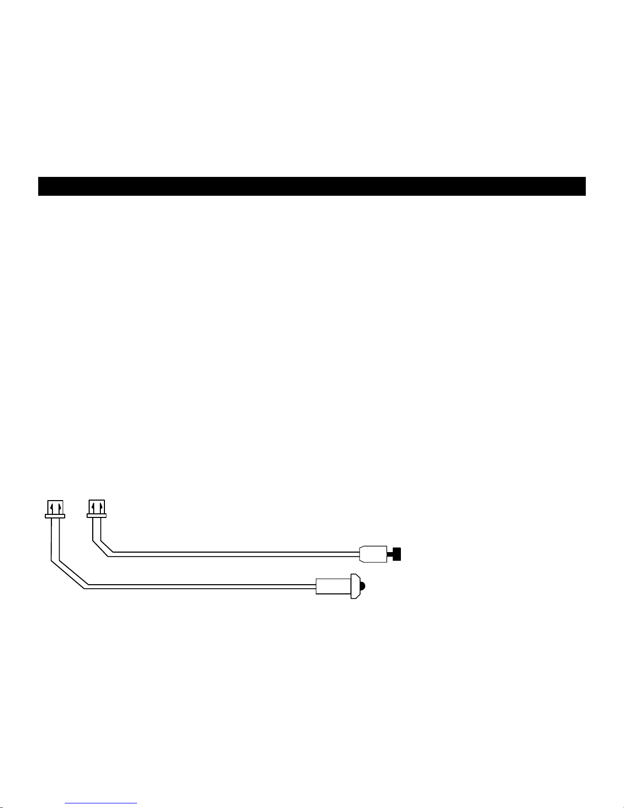
CS-6600DLM: Dual-relayplug-inmoduleforReverse
Polarity,Positive, orAftermarket Motors.
CS-6500DLI: Plug-inpulseinverterthat convertsthe
Negativeoutputsof the systemtoPositivetypeforPositive
DoorLock systems.
CS-610S1: Aftermarket doorlock actuator(motor).
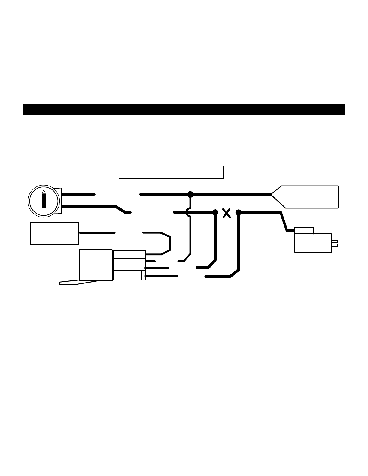
POWERDOORLOCKS:WIRING&SYSTEMTYPES
PIN1:BLUE: (-)NegativepulseforUNLOCK
PIN2:RED: 12VWhen using externalrelays(TERM86)
PIN3:GREEN: (-)Negativepulsefor LOCK
DETERMININGDOORLOCK TYPE: Werecommend
determiningthe typeoflocking systemthe vehiclehas
beforeconnectinganywires.Incorrectconnection may
resultindamagetothe alarmand/orvehiclelocking system.
Doorlockinformation isprovidedasaguide. Yourvehiclemaybedifferent.
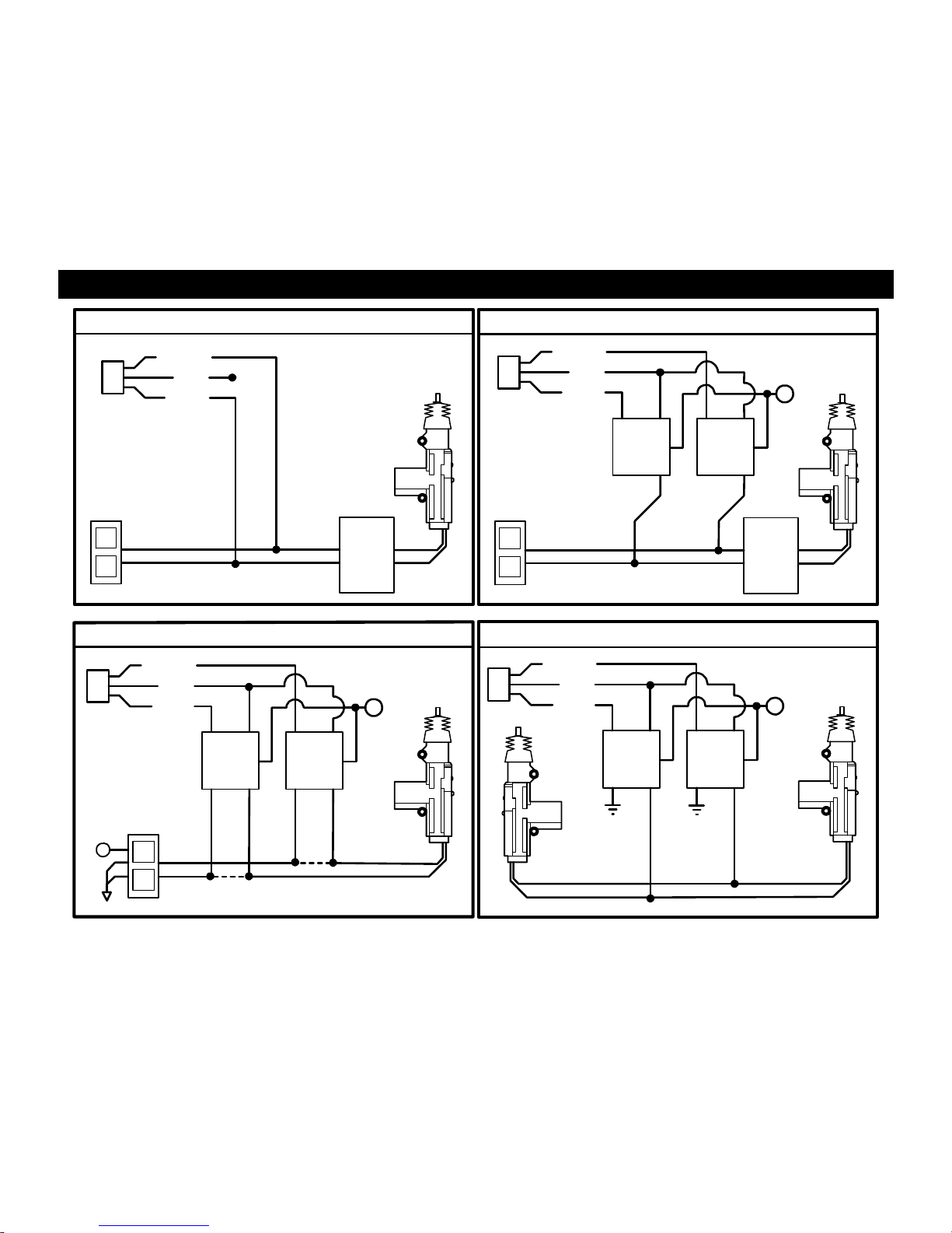
Negative Trigger(-):ManyImports;LatemodelFord&General Motors
Negativetrigger door locksystemssend aNegative(Ground) pulsetoexisting factoryrelaystolockand
unlockthevehicledoors.
Positive Trigger(+):ManyGeneral Motors;Chrysler/ Dodge/ Plymouth
Positivetriggerdoor locksystemssendaPositive(12V)pulsetoexisting factoryrelaystolockandunlockthe
vehicledoors.
Reverse Polarity:ManyFord/Lincoln/Mercury/Dodge/Chrysler/Plymouthandearly90’sGMTrucks
ReversePolaritysystemsuseno relays,butinsteadthedoor lock/unlockmotorsarecontrolleddirectlyfrom
the lockandunlockswitchesinthedoor.ThelockandunlockwiresrestatNegativeGroundwhen notinuse.
When the lockor unlockbuttonispressed,one ofthecircuitsis“Lifted”andreplacedwith+12Vcausing alock
or unlocktooccur.
SingleWire(Dual Voltage):Latemodel Chrysler/Dodge/PlymouthVehicles, some2000-UPGM
DualVoltage systemshavelock/unlock switchesthatsendvarying levelsofPositivevoltageORNegative
groundcurrent tothe SAMEwire forbothlockandunlock. When thevehicle’sBodyComputerModule(BCM)
or door lockmodulesensesdifferentvoltagesonthiswire,thesystemwill either lockor unlock.Singlewire
doorlocksystemsrequirerelaysandresistors.
DatabusandCanbusSystems(Data ModuleRequired)
Databussystemssend lowcurrent“Datamessages”tothe door lockcontrollerson anetworkinorder tolock
andunlockthevehicle.Toinstall aftermarketsystemsinthesevehicles,aninterfacemoduleisrequiredthat
convertstheregularlock/unlockpulsesinto“Datamessages”toallowlocking&unlocking.Interfacemodules
aresoldseparately.

8
POWERDOORLOCK WIRING
NEGATIVE TRIGGERDOORLOCKWIRING POSITIVE TRIGGERDOORLOCKWIRING
GREEN
GREEN FUSED
RED +12VRED BLUE +
BLUE
86
858685 8787 3087A30
87A
FACTORY
FACTORY
LLPOWER
POWER LOCKING
LOCKING
UL UL
RELAYS RELAYS
REVERSEPOLARITYDOOR LOCK WIRING
GREEN
GREEN FUSED
FUSED RED
RED +12V
+12V BLUE
BLUE +
+
86858685
86858685 8787
8787 3087A3087A
3087A3087A
+LCUT
UL CUT
MASTER
SWITCH
AFTERMARKET MOTOR/DOORLOCK WIRING

9
SEPARATEDRIVER’SDOORUNLOCK WIRING
NEGATIVE TRIGGERDOORLOCKS
BLUE/WHITE
GREEN
RED
BLUE
DRIVER'S
DOORMOTOR
8685 LL
87 ULUL
87A
30 FACTORY LOCK
RELAYS
+12V
+FUSED
UNLOCKWIRE CUT
WIRINGFORREVERSE POLARITYDOORLOCKS
BLUE/WHITE
GREEN FUSED
RED +12V
BLUE +
MASTER
86858685
SWITCH
8685 8787
87 30
87A
30
87A
30 87A
+
L
CUT
UL
CUT
CUT
UNLOCK WIRE
LOCKWIRE

10
TRANSMITTERPROGRAMMING
NOTE: All transmittersmustbe learnedatthetimeof programming. Thissystemcan learn up to4remotes.
1.Turn keytothe ONposition andpress programbutton4times.
2.After ashortdelay,the unitwill flashtheparking lights4times;Siren4times,Horn 4timesand statusLED
will be on solid.
3.Press Lockbutton ofthe firsttransmitter.Youshouldget1chirp/lightflashconfirming the remoteiscoded,
thenpress Lockbutton ofasecond transmitter,theunitwill flash2timesconfirming the remoteiscoded
and soon.If all 4codesarelearned,the unitwill automaticallyexitcodelearning mode,otherwiseturn key
off.
IGN
OFF
WAITFOR
4FLASHES
PRESS 4X's
FLASH2,3,or4X's
IGN
OFF
COMPLETE
PRESSLOCK
2VEHICLEOPERATIONand PROGRAMMING: Tosetupthe 2vehicleoperation youmusthaveall 4
remotesforprogramming.Forthefirstvehicle(remotes1&2)press theLockasinstep1thru3.Tochange
fromvehicle1tovehicle2,press the VEH buttononremoteforabout2seconds.TheLEDonremotewill
changefromgreentored.

11
OPTIONPROGRAMMING
1. Turnthe IgnitionON and press the Valet/Program button5 times.
2. After a short delay, the parking lights willflash5times, Sirenand Horn5times and statusLED willbe onsolid.
3. Withinthe nextfew seconds, press theValet/Program button[again]thenumber oftimes that corresponds to the
options chart below. Sirenand or hornshould chirp for eachpress.
4. Whenyouget to thedesired optionnumber, quicklypress theappropriate buttonontheremote control accordingto
thechart below. Thesystem willprovide 1chirp/flashfor Button1(Lock Symbol)and2chirps/flashes for button2,
3 for Button#3 and 4 for button#4. (SeeChart below for optiondescriptions and values.)
5. Whenyouare finished customizing options, turn ignitionoff and check operation.
1-WayAlarmor2-WayAlarm orKeyless Entry
Option#
OptionDescription
TXButton#1 -
Lock TXButton #2 -Unlock
*Default* TXButton#3 -
Trunk TXButton#4 -
Panic
1 SirenOutput TriggerOnly *Arm / Disarm /
Warning / Trigger* Warningand
Trigger
2 HornOutput TriggerOnly *Warning and Trigger*
3 HornChirpConfirmation
(Lock/Unlock) 1Press *2Press*
4 HornPulse (Chirp)
Arm/Disarm/Warning 15 milliseconds *20 milliseconds* 40 milliseconds
5 PassiveArming PassiveArm with
Lock *OFF* PassiveArm
withoutLock
6 ActiveRe-Arm andAuto
Re-Arm ActiveRe-Arm
withLock *OFF* AutoRe-Arm with
Lock AutoRe-Arm
withoutLock
7 DataPortProtocol ADS-OFASeries *FortinEVO Series*
8 DoorLock Pulse 3 Sec. *0.50 Sec.* DoubleUnlock
9
30 Sec. ParkingLights
withDisarm OFF *ON*
10 TrunkRelease Selection DoublePress ½Second Press 2SecondPress
11 Disarm withtrunkpop OFF *ON*
12 OpenDoorWarning 5Seconds *60 Seconds* 15 Seconds 30 Seconds
13 AutoLockwithIgnition Lock andUnlock *OFF* IgnitionLock Only

12
Option#
OptionDescription
TXButton#1 -
Lock TXButton #2 -Unlock
*Default* TXButton#3 -
Trunk TXButton#4 -
Panic
14 Arm &Disarm thruOEM
Remote(datamodeonly) ON *OFF*
15 Arm/Disarm withIGNON ON *OFF*
16 White/RedWireSelection Aux2Output *OEMDisarm*
17 Carjack Protection ACTIVE* *DISABLE* PASSIVE
18 SystemType 2-WayAlarm *1-WayAlarm* Keyless Entry
19 ResetOptionstoDefault Reset Options1thru17 (2Flashes)
Note1: OptionReset doesn'tchangesystemtype. Must useoption 18 tochange systemtype.
Note2: TheBluehoodtriggerwirecan beused toselectoption level(sameaspressing remote). Pulsethe hood wiretotoggle
throughthe option values: Pulsehood once(1chirp),Pulsethe hood again(2chirps), Pulse3or4timesforoptionsthat have3or
4values.
Note3: InKeyless EntryMode onlyalarmtriggersaredisabled, allotherfunctionswork(passivelock,passivekilletc.).
1. SIRENOUTPUT:
ThisoptioncontrolswhethertheSiren ChirpswithArm/ DisarmandWarning.Thereare 3choices:
1.Siren ActivateswithAlarmTriggeronly.
2.SirenChirpswithArm / Disarm / WarningandAlarm Trigger-Default.
3.Warning ChirpsandAlarmTrigger(noarm/ disarmchirps).
2. HORNHONKOUTPUT:
ThisoptioncontrolswhethertheCarHornsChirp withArmandDisarmand Warning.Thereare3choices:
1.HornHonkwithAlarmTrigger only.
2. Warning ChirpandAlarm Trigger -Default.
3.HORN CHIRPCONFIRMATIONwithLOCK andUNLOCK -1or2Button Press
Thisoption allowsthesystemtohonkthe vehiclehornsforLock/Unlockconfirmationon 1button press ora
2nd press within3seconds. The horn output mustbeconnectedtousethisfeature. Default=2Press.
4.HORN PULSE DURATION: Thisoption allowsadjustmentthe “CHIRP”pulsedurationofthecar horns.The
choicesare 15, 20or40milliseconds.

13
PROGRAMMABLEOPTIONSCont.
5. PASSIVE ARMING
Thisoptionisusedtoautomaticarmthealarmsystem30secondsafterthe ignitionistunedoff andthelast
doorisclosed.If adoor isreopened during the30secondcountdown,thesystemwill waitandbeginthe
countdownagainafter the door isclosed. There are3choices:
1.PassiveArmwithLock–The systemLocksthe doorswithPassiveArm. Thischoiceisbestforsecurity
but increasesthe riskof locking the keys inthe ignition.
2. OFF=Default –NoPassiveArming.
3.PassiveArmwithoutLock–The system PassiveArmswithout locking thedoors.
6.ACTIVE REARM/ AUTO REARM:
The optioncontrolswhetherthe alarmsystemrearms30secondsafterdisarm. Thisishandyifthevehicleis
accidentallydisarmedwithoutyourknowledge. Thereare 4choices:
1. ActiveRearmON–The systemwill Rearmand lockthe doorsunless thedoor, hood or trunkisopened.
2. OFF=Default -NoAutomaticRearminPassiveor ActiveMode.
3. AutoRearmwithLock-Thealarmsystemwill alwaysrearmandlockthedoorsafter disarmunless the
ignitionisturnedon. ThisappliestoPassiveandActiveMode. Thischoiceisbest for securitybut
increasestheriskof lockingthekeysinthe ignition.
4. AutoRearmwithoutLock-Thealarmsystemwill alwaysrearmwithout lockingthe doorsafter disarm
unlesstheignitionisturnedon. ThisappliestoPassiveandActiveMode.
7. DATAPORTPROTOCOL: Default=EVO / SLSeries
ThisoptioncontrolstheDataPortProtocolforADS/OFASeriesmodulesorEVO/SLSeriesmodules.The
defaultissetforEVO/SLSeriesProtocol.Thisoptionhasnoeffecton conventionalwiring ofBypass
modules. BothDataProtocolsare 2-Waycommunication.
8. DOORLOCK PULSE
Thisoptionsetshowthe doorlockcircuit works. Thereare 3choices:
1.3Second Lockand Unlock-For older Europeanvehiclesthatrequire along lockand unlockpulseto
operateVacuumdoorlocksystems.
2. 0.5SecondLock and Unlock-Default.
3.DoubleUnlock–Thisfeaturemaybe requiredtointerfacewithafactoryalarm or keyless entrysystem.
The first pulsedisarmsthe factoryalarm; the 2nd pulseunlocksthedoors.

14
PROGRAMMABLEOPTIONSCont.
9. PARKINGLIGHTSONWITHDISARMorUNLOCK:
Keepsparking lights30secondswhensystemisdisarmed toassist inlocatingandprovidingilluminationnear
yourvehiclewhenapproaching atnightfor safety.
10.TRUNKRELEASE SELECTION:
Toeliminatethe possibilityof accidentallyopeningthe trunk, thereare(3)optionsforbutton press selection.
Thisoptionwill allowyoutochange whether the Trunkreleaseactivatesbya:
1.Doublebutton -½second presses.
2. Single½second press -Default.
3.Press andHold2seconds. Aux2output staysactiveaslongasremotebuttonispressed.
11. DISARMwithTRUNKPOP:
Thisoptioncontrolswhetherthesystem will disarmwhentheTrunkreleaseisactivatedfromtheremote
control.Default=ON.
12.OPENDOORWARNING:
Thisoption changesthe delaytimeinwhichthealarmsystembeginstomonitor the Doorcircuit.Thisoption
will preventthe alarmfromgivingwarning chirpsonvehicleswithadelayeddomelight. You cansetthetime
delayfor60,30,15or5Seconds.The Default=60 Seconds.
13.AUTO LOCK WITHIGNITION:
Thisfeature controlswhetherthedoorswillautomaticallylockwhenthe ignitionisturnedonandunlockwhen
the ignitionisturnedoff. Somevehiclesalreadyhavethisfeature fromthe factoryyoushouldturn offthis
option. Doorswill notlockif theyareopen topreventlocking thekeysin.Thereare3choices:
1.LockandUnlockwithignition on andoff.
2. Off =Default.
3.Ignition Lockonly.
14.ARM&DISARMthruOEMREMOTE:
ThisoptionallowstheOEMfactoryremotetoArmandDisarmthe alarmsystem whenyou lockand unlockthe
doors.Thisfeatureonlyworkson newer CANBUSvehicleusingaDataModulethatsupportsthisfeature.
Default=Off.

15
PROGRAMMABLEOPTIONSCont.
15.ARM/ DISARMwithIGNITONON:
ThisoptionallowsyouArmandDisarm the systemwiththeIgnitionON.Thisisusedwhen thereisaremote
starter addedtothesystem. The Default=Off. Lock/unlockwithoutarmand disarmwhilethe ignition on.
16. RED/WHITEWIRESELECTION:
Thisoptioncontrolsthe functionoftheRed/whitewireaseitherOEMDisarmor2nd AUXoutput.
Default=OEMDisarm.
17. CARJACKPROTECTION:
ThisoptionenablesCar Jackprotection. There are3choices:
1.ActiveCarjack.
2. Off =Default.
3.PassiveCarjack
18. SYSTEMTYPE:
The optionselectsthetypeof system.Thissystemcanbeconfigured tooperateasaKeylessEntry,1-Way
Alarmor2-WayPagingAlarmSystem.When selectingkeylessentry,all featuresoperateexcept the alarm
triggersare disabled. The1-Waysystem usesAMtransmission.The 2-WaysystemusesFMtransmission.
The RFrangewill be muchimproved using the FM2-Wayantennasystem.Ifyouaccidentallychangesystem
from1-Wayto2-Way(orviseversa),you needtousethe hood switchwiretochangeoption18backto
correctantenna system. Note: the Keyless entrymodeonlyworksasa1-waysystem.
19.OPTIONRESET:(RESTORETODEFAULT)
Thisoptionrestoresall programmableoptions1thru17tofactorydefault. Theunitwill flashthe lights2times
andall valueswill be resettofactoryoriginalsettings. Resettingtheoptiontabletodefaultdoesnot
changethetypeofantennasystem.

16
WIRING:4-PINShock Sensor(22 Gaugewires)
SHOCK SENSOR: The sensor supplied withthissystemdoesnotrequireanyadditionalwiring.Simply
mountthesensorinasuitablelocation,plugitin,andadjustthesensitivity.Thereare2LED’sontheshock
sensor toassistyouinadjustingsensitivity.The Blue LEDindicatesthe “Warn Away”levelandthe RedLED
indicatesafull alarmshocksensorviolation.
NOTE:Yoursensor mayhave1or2adjustmentknobs(dependingonmodel)toadjustbothPre-Warn and
alarmtrigger.
BLUE LED REDLED
(-) PRE-WARN
(-) TRIGGER
GROUND
12 VOLTS
YELLOW
ORANGE
BLACK
RED
(Trigger)(Pre-Warn)
Adjustment
SHOCK SENSOR
12 VOLTS
GROUND

17
WIRINGDIAGRAM
+-
+
RED
(+)WHITE
BROWN
BLUE/WHITE
WHITE/RED
ORANGE
BLACK/WHITE
BLUE
GRAY
YELLOW
BLACK
VIOLET
GREEN
Valet/ProgramButton
BATTERY
(-) LockOutput
+12 VoltsforRelays
(-) UnlockOutput
GREEN
BLUE
RED
(-) DoorPinSwitch
(+)DoorPinSwitch
Fuse
Box
IGNITION
Switch
(-) TrunkPopAux1
(-) Hood/TrunkTrigger
(-)DoorTrigger
(+)DoorTrigger
CHASSISGROUND
(+)SwitchedIgnition "ON"
Parking
(-)Armed Output
(StarterKill)
8586
8730 87a
8586
30
87A
8586
8730 87a
10AMAX
3AMAX
Lights
FUSE
15A
CUT
STARTWIRE
IGNITION
"ON&START"
STARTER
(-)OEMDisarmorRemoteOutput2
8586
8730 87a
ShockSensor
(-) PinSwitch
(-)DomeLightOutput
+12VPOWER
+
OR
DomeLight
BROWN/WHITE
(-)HornHonkOutput
2nd Unlock
DATAPORTS
STATUS LED
ANTENNA
(-)PassengerDoorUnlock
Optional
Relay
Optional
Relay
Siren

18
ANTENNADIAGRAM
ANTENNAMODULE: Foroptimumrange and performance,the antenna shouldbelocated high upon the
frontwindshieldglass.For example:behindtherearviewmirror.Note:WindowtintsorFilmsmaydecrease
the rangeofthesystem. Themounting surfaceforthe antenna shouldbe cleanand dry.
WINDSHIELD
ANTENNA
LOCATIONS

19
DATAPORT DIAGRAM
ThisunitincludesDPTechnologythatwill allowyou todirectlyPlug-InourDataPort Bypass Modules. There
are2typesofProtocol, ADS-OFASeriesand EVO-SLseriesmodules. The default issetforEVO-SL
SeriesProtocol. PleaserefertoDatabusmodulemanualfordetail instructions.The DataPort Protocolmust
be programmed for the correct module.
See Option#7onpage9
iDATALINK CABLE
DataPort
ModuleNotIncluded
Bypass
Module 1 2 34567 8
910 11 12 13 14 15 16
BCM
OBDconnector
Datawire

20
www.crimestopper.com
Phone (800)998-6880
FAX(805)581-9500
©2012 CrimestopperSecurityProducts
ONLINETECHNICALSUPPORT
www.crimestopper.com
This manual suits for next models
2
Table of contents
Other CrimeStopper Security System manuals

CrimeStopper
CrimeStopper SP-102 User manual

CrimeStopper
CrimeStopper CS-2000DPII SERIES IV Manual

CrimeStopper
CrimeStopper Cp-4900 User manual

CrimeStopper
CrimeStopper RS901 RS900ER User manual

CrimeStopper
CrimeStopper CS-9705 Owner's manual

CrimeStopper
CrimeStopper SP-102 User manual

CrimeStopper
CrimeStopper CG-1000 User manual

CrimeStopper
CrimeStopper SP-101 Manual

CrimeStopper
CrimeStopper SP-302 User manual

CrimeStopper
CrimeStopper CS-2002DC.IV Manual