GardaWorld 2GIG-CP21-345E User manual

QUICK SETUP GUIDE
DIY Alarm System
Version 1 May 21, 2020

Need help installing your kit?
If at any point during your installation you need some
help, just give our Technical Support team a call
during regular business hours, at 1-833-427-3233.
How to complete the activation
The last step in activating your kit is for you to call
our Technical Support team at 1-833-427-3233.
They'll walk you through the free SecureNet web
application, and perform testing to ensure that our
monitoring station is receiving alarm signals from
your panel.

Control panel
The control panel must be located near an AC outlet.
It can be placed at a different location within your
home depending on how you plan to arm and disarm
the system. The system can be remotely armed and
disarmed using a key fob (sold separately), or
through the SecureNet web application. If you prefer
to arm and disarm the system using a key fob or the
web application, we recommend placing the control
panel in a central area of the home, such as on the
kitchen counter. If you prefer to arm and disarm the
system using the control panel touchscreen, we
recommend placing the control panel near the front
door, so you have ample time to respect the arming
and disarming delay (approximately 30 seconds).
1. Detach the back plate from the panel by
removing the screw at the top rear of the
panel. Once the screw has been removed,
snap off the back plate by inserting the tip of
a flat-edge screwdriver into one of the two
slots located at the top rear.
2. Snap the plastic tip of the backup battery
wire into the connector slot.
3. Reconnect the back plate and fasten it with
the screw.
4. Attach the desktop stand. The angled
deskmount stand snaps onto the rear of the
panel. It can be fitted as a high or low-
mounted stand and comes with 4 corner
grips to protect furniture and prevent sliding.
High-mounting option
Low-mounting option
5. Connect the power supply wires to the
transformer. Be careful to observe polarity.
6. Plug the transformer into a power outlet.
Backup
battery

Thin Door/Window Contact
The Thin Door/Window Contact (2GIG‐DW10‐345) is
designed for use on doors, windows, and other
objects that open and close. When the magnet
(which is mounted near the sensor) moves away
from or closer to the door contact’s sensor, signals
are transmitted to the control panel. For added
protection, it is also equipped with a cover tamper.
Figure 1 Thin Door/Window Contact
A. Thin Door/Window Contact Sensor
B. Thin Door/Window Contact Magnet
C. Alignment Marks on Sensor
D. Alignment Arrow on Magnet
Box Contents
Verify that the package includes the following:
•1—Thin Door/Window Contact
•1—Rare Earth Magnet
•2—Phillips Head Screws
•2—Lithium Coin Batteries
•2—Adhesive Foam Tape
•1—12 in (30 cm) Wire Lead
Mount Sensors within 100 ft (30 m) of the Control
Panel.
Keep Sensors and Magnets Away from
Metal/Metallic Surfaces. You should also avoid
mounting sensors in areas where there is a large
quantity of metal or electrical wiring (for example,
near a furnace or in a utility room).
Align Magnet with Sensor. Make sure the
alignment arrow on the magnet points to the center
alignment mark on the sensor (see Figure 1 Thin
Door/Window Contact—Sensor and Magnet).
Mounting the Thin Door/Window Contact
Use the figure below as a guideline when mounting
the door contact.
Figure 2 Thin Door/Window Contact
A. Access hole for external input wire (on
backplate)
B. Top and bottom mounting holes (on
backplate)
C. External input wire jack (on sensor)
D. Tamper switch (on sensor)
E. 3‐Volt (3V) lithium coin battery
compartments (on sensor)
F. Metal clips for removing batteries (on
sensor)

Motion Detector
The Passive Infrared Motion Detector (2GIG‐PIR1‐
345) is a wall-mounted unit with wide‐angle motion
protection. When set to High (HI) Sensitivity Mode,
the PIR has a maximum range of 30 ft deep x 50 ft
wide (9.1 m x 15.2 m). The PIR’s pet‐immune
feature can be set to tolerate animals up 55 lbs (25
kg).
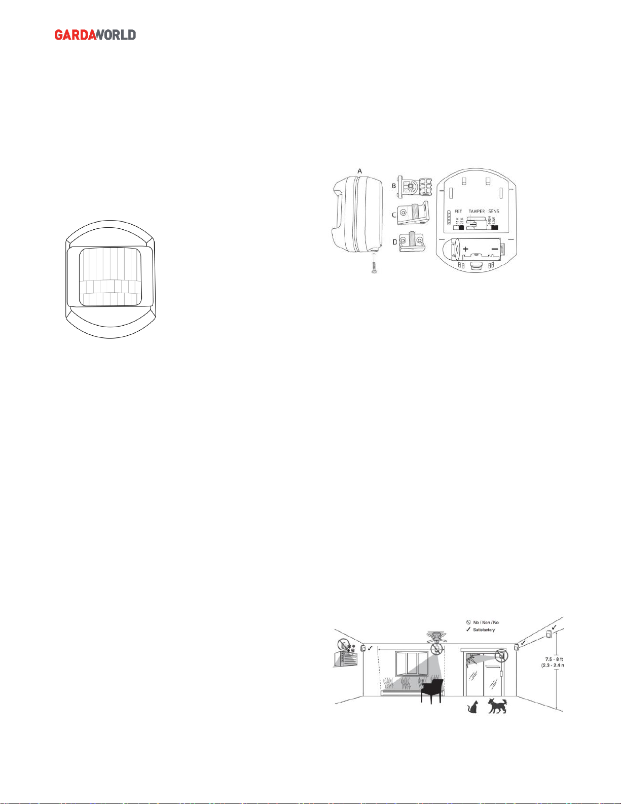
Figure 1 Passive Infrared Motion Detector
Box Contents
Verify that the package includes the following:
•1—Passive Infrared Motion Detector (Part
A)
•1—Plastic Mounting Bracket (Part B)
•1—Plastic Wall Mount (Part C)
•1—Plastic Corner Mount (Part D)
•2—Plastic Wall Anchors With Screws (not
pictured)
•1—Short Phillips Head Screw with Fender
(not pictured)
•1—Short Phillips Head Screw (not pictured)
•1—Lithium Coin Battery (not pictured)
Inserting and Replacing the Battery
To insert or replace the battery:
•Unwrap the PIR and remove the screw from
the case bottom.
•Remove the backplate using a bottom‐to‐top
lifting motion.
•Insert the battery. Always match the plus (+)
sign on the battery with the flat side of the
compartment and the minus (‐) sign on the
battery with the spring side.
•4 Replace the PIR cover.
Configuring the PIR Features
Ensure that you have inserted the PIR battery as
described in Inserting and Replacing the Battery.
Then configure the features as follows:
Figure 2 PIR Pet Immune and Sensitivity Features
Step 1: Setting the Pet Immune Feature. To set the
pet immune feature to an appropriate weight:
•Gently pull out the jumper and slip it over the
desired pins to set one of the pet‐immune
tolerance settings:
o33 LBS. Tolerates pets up to 33 lbs
(15 kg). OR
o55 LBS (Default). Tolerates pets up
to 55 lbs (25 kg).
•Continue with the next step below.
Step 2: Setting the Sensitivity Feature. Gently pull
out the jumper and slip it over the desired pins to set
the desired sensitivity mode:
oLOW (Default). Low sensitivity. This
is the recommended setting for pets.
OR
oHIGH. High sensitivity.
NOTE: Do not aim the PIR at stairs, furniture, or
other surfaces that a pet may climb on. The PIR
provides immunity when the room temperature is
above 50° F (10° C) and below 90° F (32° C).
This manual suits for next models
3
Table of contents