Ziton ZP755HAV-2 Assembly instructions

Installation Sheet No.: 1780 iss 02
ZP755HAV-2 Addressable Omni-directional Sounder Beacon
Installation sheet 501-1780ZE-1-02
ZP755HAV-2 Page 1 12/12/2005
Product description
Description
Across the world disability legislation increasingly
requires visual alarm signals to be employed to
ensure equal response from people with hearing
impairment. Conforming to EN54 Part 3, the
ZP755HAV-2 Addressable Sounder Beacon is
perfectly suited for this application and indeed any
involving high levels of background noise.
Application
It provides both audible and visual warnings from a
single, addressable, loop wired unit.
Featuring an identical profile to the ZP755 HA horn
sounder, the ZP755HAV can minimise the number of
installation points required throughout a building,
significantly lowering both the capital value of
equipment and the loop wiring costs of the completed
system.
The units high efficiency acoustic design and sound
gun transducer as well as the low current Light
Emitting Diode (LED) visual element, enables
combinations of up to 20 sounder beacons to be
connected to a one kilometer loop of 1.5mm2cable. A
plug-in base accepts all loop and screen connections,
prior to the horn sounder beacon connection.
The ZP755HAV-2 range features a unique self-test
facility - automatically activated during routine sounder
testing. A built in microphone circuit measures sound
output level and automatically signals the sounder
address and location to the control panel, should
volume fall below the expected test level.
In systems where loop lengths or current
requirements are excessive, ZP755HAV-2 sounders
can be powered directly from an external power
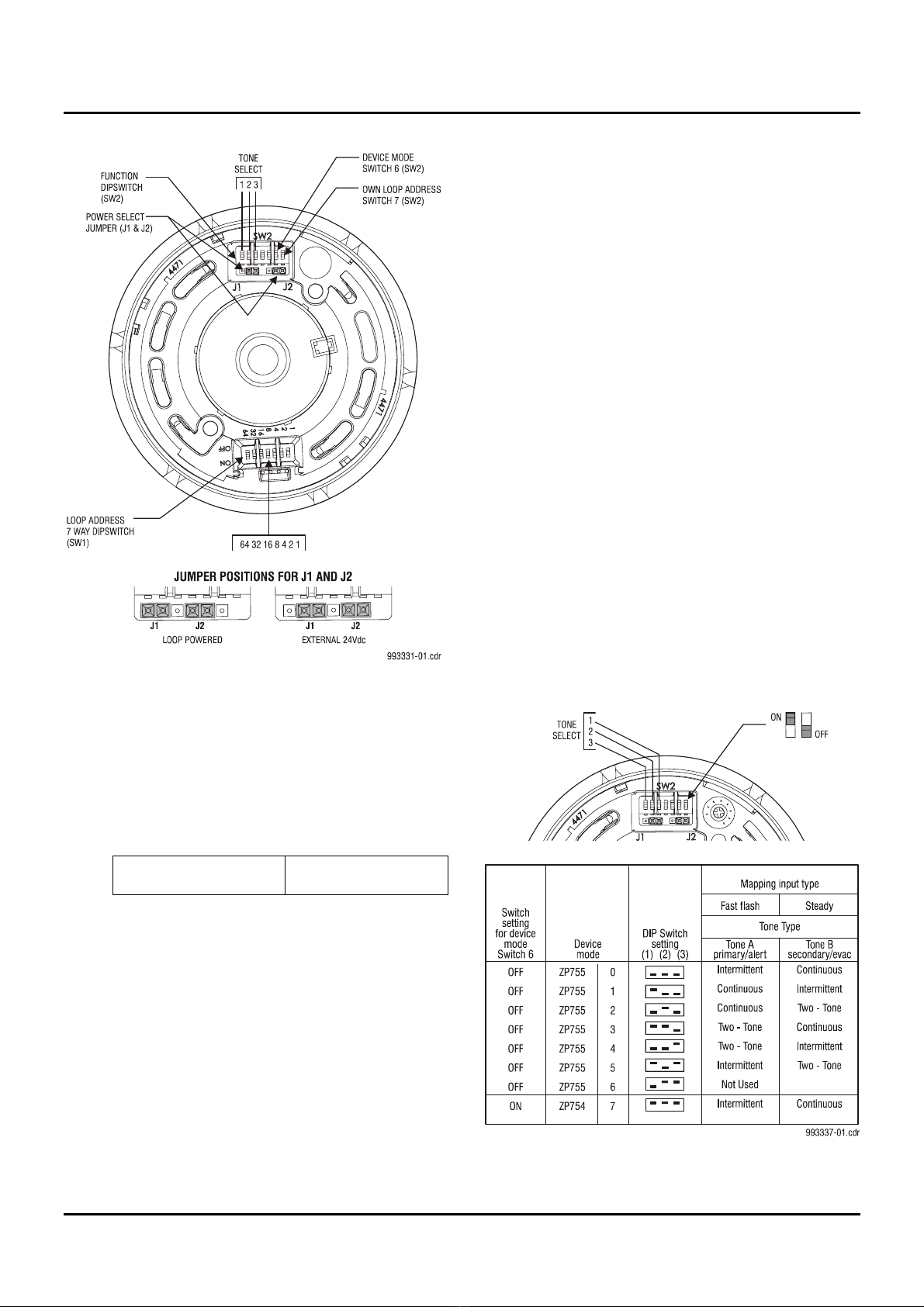
supply. All ZP755HAV-2 sounders incorporate switch
settings enabling them to be assigned a unique
address, which is polled by the panel every two
seconds.
Continuous, intermittent and two-tone outputs are
available, from which any combination can be chosen
to provide alert and evacuate, two stage alarms. All
sound types comply with BS 5839 Part 1:1988
recommended frequencies (in accordance with EN54
Part 3).
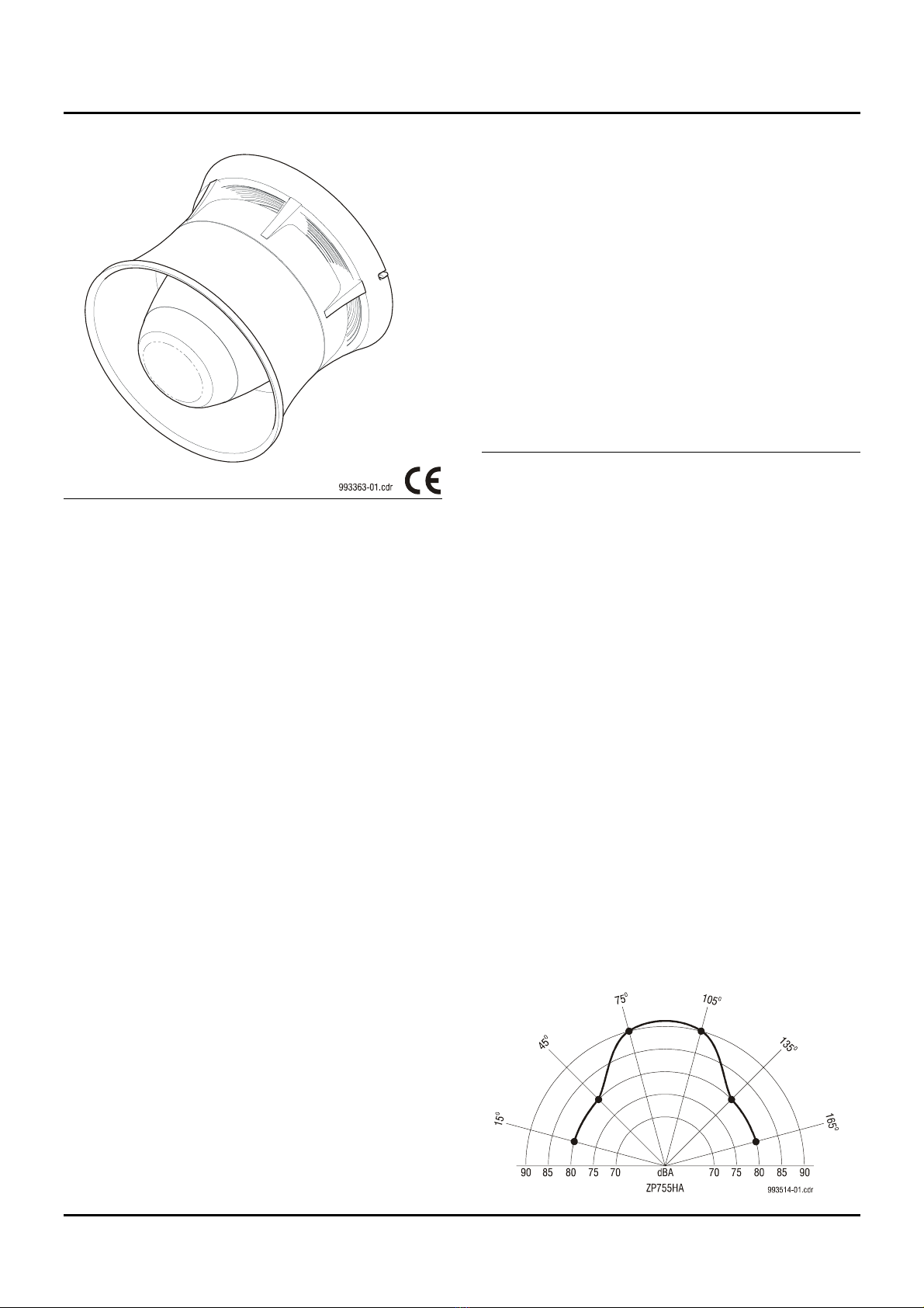
The ZP755HAV-2 features the wide sound distribution
design, with an 'all around' sound output of 90 dBA.
Moulded in high impact thermoplastic, the sounder is
available in either red or white.
Specifications
Design specification: EN54 Part 3
Designation: Addressable Omni-directional
Sounder Beacon
Model No/Part No.:
ZP755HAV-2R (Red) 178001
ZP755HAV-2W (White) 178101
Compatibility: All ZP3 analogue
addressable systems
Mounting: Surface - with plug-in base
SPB-2R (red) 180801
SPB-2W (white) 180901
Addressing method: 7 way Dip switch
Wiring: 2 core loop
Monitoring: ZP loop - open and short circuit
fault sound output level - self test
facility
Sound output:
Tone 1 continuous 980 Hz
Tone 2 intermittent 980 Hz (0.5 secs
on/off)
Tone 3 two tone warble 980 Hz/670 Hz
Sound distribution:
ZP755HAV wide
CNPP anechoic sound levels:

Installation Sheet No.: 1780 iss 02
ZP755HAV-2 Addressable Omni-directional Sounder Beacon
Installation sheet 501-1780ZE-1-02
ZP755HAV-2 Page 2 12/12/2005
Operating voltage: 16 – 24 volts, pulsed address line
Current (quiescent): 800µA
Current (average active): 11 mA
Max number: 20 per 1km loop (subject to cable
size and sounder spacing)
Light output: Equivalent to 1J xenon element
Frequency: flash rate 1.3 seconds
Environmental:
Application: Indoor use
EN60529 rating: IP50
Temp range: -10oC to 70oC
Humidity range: 10% to 95% RH (non
condensing)
EMC: CE marked
Construction:
Material: Moulded thermoplastic
Dimensions: 127mm (Dia) x 113mm (D)
Colour: White or red
Weight: 305g
Physical Installation
Connecting Wiring
Loop wiring for the plug-in base. There is no wiring
between the sounder and plug-in base. See Figure 1
below. Plug-in base supplied separately.
Figure 1
Mounting The Sounder
Align the addressable sounder to the plug-in base.
Push up (step 1) and turn the sounder until it clicks
into place (step 2). Push the sounder up once more to
engage (step 3). See Figure 2 below.
Figure 2
Operating Power
The ZP755HAV-2 can be powered directly from its
address loop (setting 1), or externally from a 24 Vdc
supply (setting 2). See Figure 3.
Setting The Address
The switch is used to set the device address in binary
code. The switch may be set to represent all
addresses from 1 to 127. See Figure 3.

Installation Sheet No.: 1780 iss 02
ZP755HAV-2 Addressable Omni-directional Sounder Beacon
Installation sheet 501-1780ZE-1-02
ZP755HAV-2 Page 3 12/12/2005
Figure 3
Operating Modes
The ZP755HAV-2 sounder has 2 modes of operation,
which are selected using switch 7 on dipswitch SW2.
It may be operated as a dedicated sounder or with a
detector fitted. See Figure 3.
1. Operation as a stand alone sounder
Own unique loop
Address Switch 7 = ON
1.1 Navigate the following menu to tag the
sounders as SAB: ZP3 Panel Menu/Setup/
Sounders/SAB/Add SAB. The Planner program
can also be used.
1.2 To map an alert to evac function the first input
type must be a fast flash input. The sounder
will sound the alert tone in response to a fast
flash input. The sounder will sound the evac
tone when the input configured as steady is
triggered, overriding the alert tone.
Emulation
The ZP755HAV-2 can operate as a ZP755HAV-2 or
emulate a ZP754. See Figure 4.
1. ZP755 mode
Set switch 6 (dipswitch SW2) to OFF. Provides
user selectable 2-tone operation and full
monitoring. Operates with ZP3 software 1.18 or
higher.
2. ZP754 Emulation Mode
Set switch 6 (dipswitch SW2) to ON. Emulates
ZP754, provides 2 fixed tones. Use with ZP5
panels or ZP3 panels with legacy software.
Tone Settings
See Figure 4 – Operating Modes.
Two different tones can be programmed to operate
from the panel. In ZP755HAV-2 mode these tones are
selected using switches 1, 2 and 3 on the function
dipswitch SW2.
For mode selection, refer to Operating Modes.
NOTE: In the ZP panel I/O mapping menu, outputs
are programmed as "steady" or "flashing". The link to
the table on the right is as follows:
Tone A = Panel setting "fast flash/slow flash.”
Tone B = Panel setting "steady.”
Figure 4

Installation Sheet No.: 1780 iss 02
ZP755HAV-2 Addressable Omni-directional Sounder Beacon
Installation sheet 501-1780ZE-1-02
ZP755HAV-2 Page 4 12/12/2005
Number of Sounders Per Loop
See figure 5.
The ZP755HAV-2 sounder can be powered directly
from the loop of a ZP5 or ZP3 panel. The table below,
read in conjunction with figure 5, gives the quantity of
detectors and sounders that can be connected to a 2
core screened loop of:
1000 metres cable size 1.5mm2
1. 10 metres panel to devices
80 detectors and 20 sounders
100 detectors and 15 sounders
2. 100 metres panel to devices
80 detectors and 20 sounders
100 detectors and 15 sounders
3. 200 metres panel to devices
60 detectors and 20 sounders
100 detectors and 15 sounders
4. 300 metres panel to devices
40 detectors and 20 sounders
110 detectors and 15 sounders
Figure 5
Other Ziton Security System manuals
Popular Security System manuals by other brands

Velleman
Velleman HAMPAG manual

Bosch
Bosch MIC-WKT-IR Installation and operation manual

Teletek electronics
Teletek electronics BRAVO Installation and operation manual

TeleAlarm
TeleAlarm TA72 user manual

AC Tool Supply
AC Tool Supply S19-320A Installation

Helios
Helios thermal imaging system instruction manual