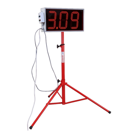
Crisartech RR400 User manual

RR400/420 User Manual -CRISARTECH
Firmware version 190122 - © CRISARTECH 2019 -Page 2/ 29
Important: videos explaining the operation of the device can be viewed and downloaded on the
page: http://www.crisartech.com/fr/rr400.html
or Youtube channel CRISARTECH:
https://www.youtube.com/user/CRISARTECH
The latest program and documentation updates can be found on this page:
http://www.crisartech.fr/download/rr400_fr.html

RR400/420 User Manual -CRISARTECH
Firmware version 190122 - © CRISARTECH 2019 -Page 3/ 29
Table of Contents
1CONNECTIONS.........................................................................................................................................4
1.1 RR400 (WITH SEPARATE INTERFACE)...................................................................................................... 4
1.2 RR420 (WITH INTEGRATED INTERFACE,BEHIND DISPLAY)........................................................................ 7
2BASIC PRINCIPLES.................................................................................................................................. 9
3FORWARD / REVERSE, STOP............................................................................................................... 10
4MAIN MENU............................................................................................................................................ 11
5VEHICLE TYPE CONFIGURATION, TESTS, CALIBRATION…...................................................... 12
5.1 VEHICLE TYPE CONFIGURATION ............................................................................................................ 12
5.1.1 Type of connection choice ............................................................................................................ 12
5.1.2 Left or Right wheel choice............................................................................................................ 13
5.2 SENSORS TEST...................................................................................................................................... 13
5.3 CALIBRATION....................................................................................................................................... 14
5.4 SIMULTANEOUS CALIBRATION OF THE GPS ........................................................................................... 15
5.5 CALIBRATION ADJUSTMENT.................................................................................................................. 15
5.6 CALIBRATION HISTORY......................................................................................................................... 16
5.7 WHEEL SENSOR MONITORING................................................................................................................ 16
5.8 BATTERY VOLTAGE MONITORING.......................................................................................................... 17
6OPERATING MODES.............................................................................................................................. 18
6.1 BEGGINER............................................................................................................................................ 18
6.2 CONFIRMED ......................................................................................................................................... 18
6.3 EXPERT................................................................................................................................................ 18
7USB DRIVE USAGE................................................................................................................................. 18
8INFRARED REMOTE CONTROL ......................................................................................................... 19
8.1 FREEZE /CHANGE DISTANCE ................................................................................................................. 19
8.2 NEW DISTANCE .................................................................................................................................... 20
8.3 MANAGING ZRS WITH THE REMOTE CONTROL ....................................................................................... 20
9ENTERING A DISTANCE ON THE FLY............................................................................................... 21
10 SHIFTED START................................................................................................................................. 22
10.1 FUNCTION ACTIVATION ........................................................................................................................ 22
10.2 AVERAGE SPEEDS CHANGES SINCE THE BEGINNING OF THE ROAD BOOK .................................................. 22
10.3 AVERAGE SPEEDS CHANGES SINCE THE BEGINNING OF THE RT ............................................................... 22
11 MULTISPEEDS MODE........................................................................................................................ 23
12 RECORDINGS...................................................................................................................................... 24
12.1 REGULARITY TESTS RECORDING ........................................................................................................... 24
12.2 GPS TRACE DURING SCOUTING ............................................................................................................. 25
12.2.1 Traces with fixed distance ............................................................................................................ 25
12.2.2 Traces with fixed time (0.1 second)............................................................................................... 25
12.3 CORRECTION WAYPOINTS DURING SCOUTING......................................................................................... 25
12.4 FILE COPYING AND ARCHIVING.............................................................................................................. 26
13 “GRAVEL CREW” NOTES ANNOUNCEMENT............................................................................... 27
14 FIRMWARE UPDATES....................................................................................................................... 28
15 WELCOME PICTURE UPDATE........................................................................................................ 29

RR400/420 User Manual -CRISARTECH
Firmware version 190122 - © CRISARTECH 2019 -Page 4/ 29
1 Connections
1.1 RR400 (with separate interface)
Warning: the interface provides a power supply for the sensors which is protected by a fuse. A fuse holder is
located on the side of the housing. A 200 mA fuse is supplied as standard (plus a replacement fuse). This value is
suitable for most sensors on the market, but it is up to the installer to check if it is correct for sensors other than
those supplied by CRISARTECH.

RR400/420 User Manual -CRISARTECH
Firmware version 190122 - © CRISARTECH 2019 -Page 5/ 29
The harness for connection to power supply can be replaced by the OBDII harness that plugs into a modern vehicle
(after about 2006).
4 ways connector for power supply and CAN bus:
Contact name Remark Num. Colour
old car Colour
modern car
+12V permanent power 1/4 M Brown Red
Ground 2/4 M Black Blue
CAN H on ODBII 3/4 M / Yellow
CAN L on ODBII 4/4 M / Green
3 ways connecteur -BLACK for RIGHT wheel sensor:
Contact name Remark Num. Colour
+12V power for sensor on fuse holder 1/3 F Red
Ground for sensor 2/3 F Blue
R wheel signal 3/3 F Green
3 ways connecteur - WHITE for LEFT wheel sensor:
Contact name Remark Num. Colour
+12V power for sensor on fuse holder 1/3 F Red
Ground for sensor 2/3 F Blue
L wheel signal 3/3 F Green
Tip for connectors with crimping pins:
-use crimping pliers for pins rather than welding,
-reinforce the output of the wires with adhesive lined heatshrink Tub (morerigid),
-these "automotive" connectors have a double locking system: when the spindle is fitted, a small click is heard:
first locking. Once all the pins are in place, the second system must be locked:
oyellow plastic part for male connectors,
oLid of the same color for females.
If one of the pins is not in place, it is not possible to close the second lock. If this second locking is not
properly installed, the connector can not be connected.

RR400/420 User Manual -CRISARTECH
Firmware version 190122 - © CRISARTECH 2019 -Page 6/ 29
The resistance to put between the blue wire and the mass is 750 Ohms 1/4 watt for the sensors:
-Blunik Carlo Gavazzi inductive,
-Inductive Terratrip T005 ...
The optional "pilot" display connects to the 4-pin connector located to the power supply:
Caution: the infrared receiver for remote control is placed on the harness, just below the display connector.
It must be ensured that lens is not masked and turned towards the co-pilot so that the infrared remote
control is fully operational.

RR400/420 User Manual -CRISARTECH
Firmware version 190122 - © CRISARTECH 2019 -Page 7/ 29
1.2 RR420 (with integrated interface, behind display)
Important: the plastic case manufactured by 3D printing does not withstand the temperature
that can be found in a closed car, under a windshield, in the summer sun. Therefore, if your
car must stay parked in the sun, we advise you:
- remove the RR420 from the vehicle or place it in a cooler place (trunk ...),
- if this is not possible, turn off the RR420 and use a solar ray reflector (metallized accordion
placed under or better on the windshield) and leave the windows open,
- in last resort, turn off the RR420, place a white cloth on the RR420 and leave the windows
open,
- do not leave the cloth on the RR420 during use.

RR400/420 User Manual -CRISARTECH
Firmware version 190122 - © CRISARTECH 2019 -Page 8/ 29
Connections:
"Universal" 4-wire harness connected to 2-wiressensor (gray connector, 4-pin):
+12V 1 Red Red Red Usually sensor brown wire
Ground 2 Blue Black Black Notconnected
Signal 3 Green Orange Orange Notconnected
Ground -Signal 4 Yellow Yellow Brown Usually sensor blue wire
"Universal" 4-wire harness connected to 3-wiressensor (gray connector, 4-pin):
+12V 1 Red Red Red Usually sensor brown wire
Ground 2 Blue Black Black Usually sensor blue wire
Signal 3 Green Orange Orange Usually sensor black wire
Ground -Signal 4 Yellow Yellow Brown Notconnected
Harness for 3-wiressensor (gray connector, 4 points):
+12V 1 Red Usually sensor brown wire
Ground 2 Blue Usually sensor blue wire
Signal 3 Green Usually sensor black wire
Beam for 2-wiressensor (gray connector, 4 points):
+12V 1 Brown Usually sensor brown wire
Ground -Signal 4 Black Usually sensor blue wire
Power harness (black / blue connector, 4 points):
+12V 1 Red Brown Red
Ground 2 Black Black Blue
Note: The RR420 provides a power supply for sensors that is protected by an automatically resettable fuse. There is
nothing to do in case of a short circuit.

RR400/420 User Manual -CRISARTECH
Firmware version 190122 - © CRISARTECH 2019 -Page 9/ 29
2 Basic principles
This timer uses a touch screen for the configuration, calibration, speed input ...
To modify an item, press the item zone. In "beginner" mode, the user is guided by a grid that indicates the different
sensitive zones:
-"chrono"
-"trip"
-'ZR'
-"correction cancellation"...
The page change is made by pressing outside these areas, next page on the right and previous on the left, in
blue and green respectively on the following images:
buttons allow you to go back, exit the configuration pages...
Warning: if a parameter has been modified, the modification is saved!
Do not forget to use the help buttons when in doubt (except expert mode):

RR400/420 User Manual -CRISARTECH
Firmware version 190122 - © CRISARTECH 2019 -Page 10 / 29
3 Forward / Reverse, Stop
To access the RND panel (analogy to the automatic gearboxes):
-press the screen (top-middle of preference) then on the button that appears in the top left,
-press the key on remote control Philips or key on the “one for all”
-Rfor "Reverse"
-Nfor "Neutral" or stop counting,
-Dfor "Drive" or Forward.
Then press the desired operating mode or use remote control: or
This panel will only be displayed when the position is different from "Drive".
Special case in GPS measurement:
Tunneling is a serious problem because the signal is gradually lost and the speed transmitted by the GPS becomes
erroneous before the signal is lost. To avoid this, it is possible to block the speed before entering the tunnel. By
driving at constant speed, it is possible to cross the tunnel without too much distance error. The manipulations to do
are the following:
-display the above sign before arriving in the tunnel,
-press D to block the speed and display the following panel:

RR400/420 User Manual -CRISARTECH
Firmware version 190122 - © CRISARTECH 2019 -Page 11 / 29
-cross the tunnel at the most stable speed possible,
-when leaving, press again on this panel to resume the GPS speed.
Note: with remote control: press or to lock / unlock GPS speed.
4 Main menu
To access the main menu, press the screen (top, middle preferably) and then the yellow button that appears:

RR400/420 User Manual -CRISARTECH
Firmware version 190122 - © CRISARTECH 2019 -Page 12 / 29
5 Vehicle type configuration, tests, calibration…
In the main menu, press the button with tools:
5.1 Vehicle type configuration
In the following menu, press the button with auto and ruler:
5.1.1 Type of connection choice
Start by choosing the type of connection:
-GPS (not very accurate),
-OBDII (diagnostic socket), then the vehicle type. Those marked "ABS" have a very precise measurement of
the distance (from 1 to 10 cm). "Obd 11 bits" and "Obd 29 bits" are universal but not very accurate (1 to 3 m
error per km). This precision is sufficient in the race because it is negligible in relation to the trajectories cut
but insufficient for the measurements carried out for creating road-books or scouting,
-wheel speed sensor (s).Three configurations (A, B, and C) are proposed, corresponding to3 different types
of tires. This makes possible to memorize in the device 3 calibration values that will be associated with each
type of tire. By changing the wheel during the race, simply change the configuration here, without having to
change the value by itself,
-speed simulation (speed is set with two buttons).
These points can be "swept" using the up and down arrow keys on the remote control. InOBDII configuration,
the red and blue function keys are used to select the type of vehicle.

RR400/420 User Manual -CRISARTECH
Firmware version 190122 - © CRISARTECH 2019 -Page 13 / 29
5.1.2 Left or Right wheel choice
When possible, a panel at the bottom of the screen can then choose whether the distance should be measured on
the right / left / average of the two wheels.
These choices can be "swept" using the left and right arrow keys on the remote control.
Note:
-with“Peugeot/Citroën ABS” OBDII configuration 4WR check box add 2 more wheel inputs (front wheels),
-with the Capteur/sensor configuration, two checkbox add the sensor monitoring function based on the GPS
(Compare GPS),or on left/right wheel sensor comparison (Compare L/R), see below.
-Then go to the "Calibration" tab (Page key on remote control).
Remote control usage:
5.2 Sensors test
If the system allows it (wheel speed sensor or OBDII in ABS mode), the Detailled distances button displays the
pulses sent by the sensors via the page (the number of counters can be different according to the configuration):

RR400/420 User Manual -CRISARTECH
Firmware version 190122 - © CRISARTECH 2019 -Page 14 / 29
This page help to compare all the wheel “sensors”, the distance calculated for each wheel,
the GPS distance calculated and Trip1, based on the configuration and the above distances
In case the timer is connected to wheel speed sensor (s), first check that each pulse increments the counter of
the rotating wheel.
At the end of the installation, before calibration, carry out a test by accelerating progressively up to the
maximum speed of the vehicle. The displayed speed must be stable (even if it is false because not yet calibrated).
If this is not the case, the speed sensor(s) are incorrectly adjusted:
-if the speed tends to fall to 0 beyond a certain speed, the sensor misses tops at high speed, it must be too far
from the "target" or "target" is not of good "ferromagnetic quality",
-if the speed tends to double at certain times, the sensor records "rebounds". This can happen with ILS sensors
when they are too close to a very powerful magnet. Or problems of false contacts
5.3 Calibration
Once measurement configuration has been chosen (GPS, OBDII, or sensor), it is necessary to calibrate for your
device measures the distances precisely, but especially in the same way as that of the organizer. The RR400 uses a
very precise calibration coefficient. Or rather several coefficients:
-calibration coefficient when the measurement is made by GPS (the value is about 1),
-calibration coefficient when the measurement is made by the OBDII socket (the value is about 1),
-3 calibration coefficientswhen the measurement is made by the wheel speed sensor (the value corresponds to
the distance of a sensor top, ie the perimeter of the wheel divided by the number of tops per revolution), one
coefficient for each tyre type (A, B or C),
-calibration coefficient when the speed is simulated (the value is about 1).
But this coefficient is then used to measure ALL distances (Trip1 to Trip3, and Totalizer)
On the calibration page, select the calibration mode:
-Trip1 uses the first counter to perform the calibration. This is the default mode, the simplest,
-Trip2 uses the second counter to perform the calibration. Used to calibrate (or refine calibration) during the
first ZR. In this case the Trip1 was used and adjusted during the ZR, so not usable to calibrate. Trip2, on the
other hand, has not been modified and can be used to calibrate at the end of ZR, using the theoretical distance
written on the road-book.The advantage is to have a distance generally longer than the calibration zone and
taking into account the cut curves (driving style),
-Free calcul: here only the function of "special calculator with rule of proportionality " is used: calculation of
the calibration from a distance that has been measured before and the corresponding theoretical distance,
-GPS: to perform a rapid calibration of the speed sensors, we use the GPS speed. This method does not have
the precision required to perform a rally, but allows a quick calibration after the sensor test. This allows you to
have a correct speed displayed in the main page without needing to go on a calibration zone, but does not
replace in any case a real calibration at the beginning of the rally.
Typical case of Trip1:
-drive to the the beginning of the calibration zone,
-press button "0.000"
-drive to the end of calibration zone, the distance is displayed in the left field,
-enter the zone theoretical distance in the right field,
-then press the "Compute" button: the new value is displayed next to it.

RR400/420 User Manual -CRISARTECH
Firmware version 190122 - © CRISARTECH 2019 -Page 15 / 29
Congratulations, it's over!
5.4 Simultaneous calibration of the GPS
When one or more speed sensors are used to measure the distance, the GPS can be used as a backup measurement
means in case of failure of the sensor (s). For this purpose, the GPS must be calibrated in the same way as the speed
sensors. On the calibration area, just check the box:
By calculating the calibration coefficient of the speed sensors, the RR400 calculates the calibration coefficient of
the GPS and displays it in an information panel. It must be close to 1.
5.5 Calibration adjustment
If the co-pilot realizes that his calibration is not optimal, he can easily adjust it in percentage (except beginner
mode). In the calibration screen, the button opens a window allowing this adjustment:
For memory, here are the percentages or coefficients to apply according to the desired corrections:

RR400/420 User Manual -CRISARTECH
Firmware version 190122 - © CRISARTECH 2019 -Page 16 / 29
number of m. / Km
to correct %of
correction multiplier coefficient
to apply
10 1 1.01
5 0.5 1.005
1 0.1 1.001
0.5 0.05 1.0005
-0.5 -0.05 0.9995
-1 -0.1 0.999
-5 -0.5 0.995
-10 -1 0.99
5.6 Calibration history
The button is used to display a table of the different calibration values calculated on the device:
Date –hour Source Method Calibration
2018/09/01-07:24 OBD MAN 1.025399
2018/09/01-07:28 GPS MAN 0.9869231
2018/09/01-07:31 Sensor A MAN 0.4893265
2018/09/05-16:08 Sensor A % 0.4895712
2018/09/05-16:08 Sensor A MAN 0.4895712
2018/09/05-16:08 Sensor A TRIP1 0.4886692
2018/09/05-16:08 Sensor A MAN 0.4886692
2018/09/05-16:08 Sensor A TRIP2 0.4893671
2018/09/05-16:09 Sensor A MAN 0.4893671
2018/09/05-16:09 Sensor A FREE 0.4898044
2018/09/05-16:10 Sensor A GPS 0.4895166
The Source column corresponds to the input selected to calculate distances that has been calibrated (GPS, OBDII,
Sensor A, B, C or simulation).
The Method column recalls which method was used to change the calibration:
-MAN: the calibration value was entered directly with the keyboard,
-TRIP1 or TRIP2: the value has been calculated on a calibration zone,
-FREE: the value has been freely calculated based on a distance traveled and a reference distance,
-GPS: the value was calculated approximately using GPS speed,
-%: the value has been adjusted by percentage.
Note: during TRIP1, 2 or FREE calculations, the value before calculation is recalled on the top line in MAN.
The button deletes the table.
The file containing these data is copied to the USB drive at the same time as the race recordings and can be
archived with this data.
5.7 Wheel sensor monitoring
Specifically for the Capteur/sensor configuration it is possible to activate the sensor signal monitoring function
by ticking the Compare GPS or Compare L/R box in the configuration tab of the input used for speed
measurement. The distances measured by the sensors left and right and/or the GPS are compared and if a significant
difference appears, an alert popup is displayed in the main running screens:

RR400/420 User Manual -CRISARTECH
Firmware version 190122 - © CRISARTECH 2019 -Page 17 / 29
The red LED flashes if the corresponding box is checked in the alert configuration screen:
Menu - Config. equipment -Alerts config.
By removing this popup, we can display the percentages of error, which allows to better understand the problem:
-if a slight difference appears between right and left, following a succession of turns in the same direction, we
can consider that it is a false alarm, but it is necessary to monitor the / the sensors,
-if a slight difference appears after changing tires, you must change the calibration,
-if a difference with GPS appears after having crossed a tunnel, an avalanche barrier, or a verydense forest, it is
normal the GPS lost some meters,
-if a significant difference suddenly appears, a sensor may be faulty, especially not perform “on-the-fly”
correction (+/-1 or 10 m key) before confirming or reversing this assumption. To do this, go to the
detailed distances page to monitor the distances of each sensor. If the failure of one sensor is confirmed, use
the other or the GPS. The most correct distance will be restored automatically when the faulty sensor is
ignored, because the distances (L wheel,R wheel and GPS) are measured separately,then selected or averaged
to serve Trip1. But during a correction, the three are synchronized, that's why we must not correct “on the fly”
when we have a doubt.
action on the touch screen: action on the remote control: the test resumes after:
hide popup and display
the percentages of error maintained push (2 seconds) INFO key 30 seconds
simply hide popup simple push other key 2 minutes
There are three parameters to fill in:
-measurement distance before comparison (in km), common for both tests,
-maximum error for left / right wheel comparison (in%),
-maximum error for GPS and wheel comparison (in%).
This function can be used in two ways:
-monitoring "health" sensors: put a distance short enough to quickly detect a failure (0.15 km for example) and
a maximum error large enough to avoid false alarms (5% for example),
-calibration error detection (forget calibration change after changing wheels for example): put a distance long
enough to avoid false alarms (0.8 km for example) and a maximum error strict enough to detect small errors (1
% for example).
The given values are indicative and are to be refined before the rally according to the configuration (number of
pulses per revolution for example).
5.8 Battery voltage monitoring
The battery voltage is displayed in the link screen.
In case of low or high battery level, a warning popup is displayed in the main running screens. The ignition
thresholdscan be changed in the alerts configuration page and the red led can follow the display of the popup:

RR400/420 User Manual -CRISARTECH
Firmware version 190122 - © CRISARTECH 2019 -Page 18 / 29
Menu - Config. equipment -Alerts config.
6 Operating modes
This system has 3 operating modes, to be chosen at the bottom of the main menu, depending on the co-pilot's
experience.
6.1 Begginer
This mode displays a help grid to know the different sensitive areas.
It hides certain complicated parameters:
-clock shift,
-setting the number of km / h by buzzer beep,
-conditions of lighting of the bargraph,
-number of meters added / removed with each press on button box ...
Attention: the automatic start of the chrono can only be done on each full minute.
6.2 Confirmed
Mode to be used as soon as the user feels comfortable with the machine to take full advantage of it.
6.3 Expert
This mode deletes the help buttons and adds a history of distance modifications, manual or automatic (GPS).
7 USB drive usage
Important:
It is strongly recommended to format your USB drive on the device before using it. This
function erases ALL data and then formats and conforms it for use with this device.
To access this function, in the main configuration page, press the button with the USB drive:
->
Attention:
-this operation erases ALL the data present on the key, even if they were written with a computer or a tablet,
-it is advisable to wait ten seconds after the end of the operation, when the display asks to remove the key.

RR400/420 User Manual -CRISARTECH
Firmware version 190122 - © CRISARTECH 2019 -Page 19 / 29
8 Infrared remote control
The decimal point is obtained with the key at the bottom right for Philips (formerly "reset to 0" or "---") or
left for OneForAll:
As soon as the remote control is used, frames in red, green, yellow, blue appear in certain areas or buttons. These
zones are activated by pressing the corresponding function keys on the remote control:
8.1 Freeze / change distance
To freeze the distance, use the OK key. this value can be changed with the number keys or with +/-1 or +/-10 m.
The new value appears in blue and the difference in green. When validating with the OK key, the difference is
applied, that is to say that the trip takes into account the distance that runs during the time of manipulation:
Example:
-freeze distance to 14,226 km. in front of a sign,
-on the road-book is written 14,235 km for this panel. We type this value,
-valid further at km 14.600, the trip goes to 14.609 km applying the difference.
Notes:
-the difference display (in green) may be hidden in the co-pilot page configuration.
-the frozen value is displayed in meters as part of the command history, bottom right, and during the race, it is
saved in the trace file (preceded by the letter F), if this action is not canceled with BACK or EXIT key.

RR400/420 User Manual -CRISARTECH
Firmware version 190122 - © CRISARTECH 2019 -Page 20 / 29
8.2 New distance
To force a new distance, use the numeric keypad and then valid with the OK key.
Example:
-on the road-book is written 14,235 km for a sign. We type this value before reaching the sign,
-valid in front of the panel, the trip passes to 14.235 km applying the new value.
8.3 Managing ZRs with the remote control
To change the ZR, use the green and yellow keys.
To program the distances / speeds in ZR, use the arrow pad to move the active box, then simply type the distance or
speed and validate with "OK" key:
Save with the red key.
This manual suits for next models
1
Table of contents


