Cross point XM3 MICROPROXS User manual

INSTALLATION MANUAL
XM3 Reader


Conditions Transactions, deliveries et cetera will be according to the general terms of
delivery as deposited at the Chamber of Commerce at Meppel, The Netherlands.
Registration number is K.v.K. 04058425.
Version 1.2 (25-08-2011)

Table of contents II
Table of contents
1Introduction .....................................................................................1
2Installation information.....................................................................2
2.1 Product label..........................................................................2
2.2 Power supply .........................................................................2
2.3 Connecting the wires..............................................................2
2.4 Explanation of the XM3 LED indicators..................................4
3XM3 Operating levels......................................................................5
4Configuring the XM3........................................................................6
4.1 Configuring the XM3 using XM3 Manage software.................6
4.1.1 Install XM3 Manage....................................................6
4.1.1.1 Define a name for the reader........................6
4.1.1.2 Set reader parameters .................................7
4.1.1.3 Switch Authorization Level ...........................7
4.2 Configuring the XM3 with a Remote Programmer ..................8
4.2.1 Wake up the XM3 from sleep mode............................8
4.2.2 Set Open Time-out (11*).............................................9
4.2.3 Set Egress (20*) .........................................................9
4.2.4 Set XM3 from Installer level to User level..................10
4.2.5 Learn the User Remote Programmer........................10
4.2.6 Set XM3 to sleep mode on User level.......................10
4.3 Configuring the XM3 using Master Cards.............................11
4.3.1 Learn the Program Master........................................11
4.3.2 Learn other Master Cards.........................................12
4.3.3 Set Open Time-out with Master Cards......................14
4.3.4 Set Close Time-out with Master Cards......................15
4.3.5 Adding cards with the Add Master Cards..................16
4.3.6 Voiding cards with the Void Master...........................16
4.3.7 Night Lock mode.......................................................17
4.3.8 Unlock mode.............................................................18
5Security.........................................................................................19
5.1 Privacy.................................................................................19
5.2 Forced entry.........................................................................19
5.3 Molest..................................................................................19

Introduction 1
1 Introduction
Thank you for using XM3 MICROPROXS™ for your access control
application. XM3 is a powerful access control system which can be used for
single door access, as well as for connection to any type of on-line access
control system.
XM3 MICROPROXS™ units can also be mounted in an RS485
network without the need of a separate access control system.
XM3 as stand-alone unit offers many possibilities such as:
Access control
XM3 Manage software for stand-alone PC programming, event
logging and user database maintenance
Unlock option (during working hours)
Day/Night lock option (manual or automatic switching)
Master/slave installation
Optional use of a wireless PIN keypad
Using an external relay (to prevent potential tampering)
For further information please visit our website at www.crosspoint.nl.
NOTE If you use XM3’s in a network, be sure that all readers have a unique
address. Cross Point delivers XM3 with an address between 1 and 31. If you
don’t want to change the address on location, be sure that you bring XM3’s
with unique addresses that can be found on the reader or on the package.

2 Installation information
2 Installation information
2.1 Product label
The product label of the XM3 is located under the plastic cover. Remove the
cover to view this information.
The label contains the following information:
Manufacturer name
Product name
Serial number
Production date
Default address (between 1 and 31)
Input power: 12V DC, 40mA
Technology
Firmware version
CE marking
Alert sign
WEEE marking
2.2 Power supply
The XM3 requires a 12V DC power supply. It is advised to use a UL listed
Access Control power supply.
Since the XM3 requires a permanent power supply, it is required that a
readily accessible disconnect device is incorporated external to the
equipment.
2.3 Connecting the wires
A 12 wire E111235 AWM STYLE 2560 60°C 30V low voltage computer cable
is used for the XM3. In Table 1 the connections are listed.

Installation information 3
Wire
Stand-alone
Magstripe (ABA)
Wiegand
Brown
Extra ground
Violet
Relay out (O.C.)
Black
Ground
Red
Power (+11,5 -
+12.5 VDC)
Yellow
RS-485B in +
Blue
RS-485B out -
White
RS-485A in +
Pink
RS-485A out -
Grey
IO1 Door contact
input
\ RDP output
DATA 0
Green
IO2 Ext. Night
lock/Rec. ingang
\ RCP output
DATA 1
Grey/Pink
IO3 Forced entry
output
\ CLS output
Red/Blue
IO4 Night lock
enabled output
\ Access input
\Access
Table 1: Wiring the XM3

4 Installation information
In Figure 1, a graphical representation of the connections is given.
Figure 1: Connection of the XM3
2.4 Explanation of the XM3 LED indicators
The XM3 is provided with seven LED’s which serve as status indicators. In Figure 2
their meaning is described.
Figure 2: LED indicators XM3
Alarm system
Controller
Next reader or Line
Terminator
External Clock
klok
Door contact
Lock or external relay
Power supply 12V DC
Wire
White
Yellow
Pink
Blue
Grey
Green
Grey / Pink
Red / Blue
Violet
Brown
Red
Black
Notes:
1. Connect to UL listed Access Control
System Power Supply
2. The relay output is a 1A / 30V open
collector.
3. With the XM3, only DC locks can be
used when directly connected to the
XM3. Use the XMSS1 surge
suppressor.
LED 1 (yellow) Indicates that a tag/remote programmer is within range of the XM3
LED 2 (green) Indicates that access is granted or that the XM3 is in Unlock Mode.
LED 3 (red) Indicates that the door is closed
LED 4 (red) Indicates that the XM3 is in Night Lock mode
LED 5 (red) Indicates that the XM3 is in Add mode, and that cards are added
LED 6 (red) Indicates that the XM3 is in Void mode, and that cards are voided
LED 7 (red) Indicates that the XM3 is in Program Mode

XM3 Operating levels 5
3 XM3 Operating levels
The XM3 Proximity Reader distinguishes two operating levels:
Installer Level. On this level the XM3 can be configured by the
Installer. This level is also used to do typical Installer options.
User Level. On this level typical user options can be set. Think of
adding and voiding user cards, setting the door open time et cetera.
The programming steps mentioned in this manual represent a limited number
of programming functions that can be performed by the Installer on an XM3.
Please refer to the XM3 Master Manual for all the possibilities.

6 Configuring the XM3
4 Configuring the XM3
The XM3 reader can be configured in the following ways:
Using XM3 Manage
Using a Remote Programmer
Using Master Cards
4.1 Configuring the XM3 using XM3 Manage software
XM3 Manage is a PC application for stand-alone and networks of XM3
readers. Using XM3 Manage requires an advanced connection unit. Please
refer to the connection unit manual for connections. For more information on
how to program the XM3 by using XM3 Manage, please refer to the Users
guide XM3 Manage.
4.1.1 Install XM3 Manage
To install XM3 Manage, take the XM3 Manage CD and insert it into your
computer. Follow the instructions on the screen to install the application.
After installation, select the application in the start menu that is located on:
All Programs\Cross Point\XM3 Manage 4.0.
NOTE The very first time that you start XM3 Manage, you are prompted to create an
account for logging on to the application. Follow the instructions on the
screen. The configuration Wizard is started and will configure your readers to
communicate on the right baud rate and with the right file system. If you are
missing readers, please check their addresses and see if they are all unique.
4.1.1.1 Define a name for the reader
In XM3 Manage, you can define a name for each reader. Select the reader in
the box on the upper left of the screen and select the menu item Reader ->
Change Name. Now you can change the reader name.
NOTE If you do not know where the reader was mounted and you need that
information to give it a name, select Reader -> Locate to locate the reader.
Once you have identified all your readers, you can proceed with the next
paragraph.

Configuring the XM3 7
4.1.1.2 Set reader parameters
Now the reader parameters can be set. The parameters that have to be set
on Installer authorization level are listed below. See the respective chapter in
the Users Guide XM3 Manage on how to do these settings.
Open time
Close time
Lock type
Egress (request to exit Rex)
NOTE If you have more than one reader in your network, you can repeat the
previously mentioned steps again or you can transfer the settings to the other
readers.
4.1.1.3 Switch Authorization Level
The last step you have to do is to switch the readers to user authorization
level.
Since during normal operation, the readers are at User authorization level,
you have to switch to that level after the readers have been configured. Take
the following steps to switch the level:
1. From the Menu bar, select Reader -> Switch operational level. The
Switch Reader Level dialog is displayed.
2. Select the box Switch all readers to switch all readers in your
Access Control system to the User level. When at Installer level and
you want to switch to User level, the button User level is already
selected.
3. Select the button Switch.
4. A processor indicates that switching is taking place.
5. Select the button Close to return to the application.
NOTE During normal operation it may be necessary to switch to Installer level to do
some changes. Remember that after the changes have been made you have
to switch back to the User level.
Now you have completed all the steps required to get a reader started. The
end-user now can start creating accounts, managing users et cetera.

8 Configuring the XM3
4.2 Configuring the XM3 with a Remote Programmer
A remote programmer can be used to configure the XM3 and do
settings in the XM3 by bringing it into the RF field of the XM3.
The reading range of the programmers is max. 20mm. A
programmed function may look like as follows:
The “n” in the function indicates an optional number.
NOTE An Installer Remote Programmer can set all functions of the XM3. The User
Remote Programmer enables you to program the user specific functions.
Please refer to the Remote Programmer Manual for an overview of the
differences.
The following steps describe on how to configure the XM3.
4.2.1 Wake up the XM3 from sleep mode
When you power up the XM3 from sleep mode, the XM3 is at Installer sleep
mode.
NOTE This programmer will become automatically the Installer Remote
Programmer. It is convenient to identify the Remote Programmer as the
Installer by labeling it.
The steps to wake up the XM3 are displayed in Figure 3.
1. Power on (XM3 is installer
sleep mode).
2. Present a remote programmer in the
RF field of the XM3.
3. Normal operation of the
XM3 is resumed.
Figure 3: Wake up the XM3 from sleep mode

Configuring the XM3 9
4.2.2 Set Open Time-out (11*)
Whenever access is granted, the relay of the XM3 will be activated during a
certain number of seconds, called the Open Time-Out.
This period of time can be adjusted from 1 to 255 seconds. The default value
is 2 sec, meaning that after presenting the tag to the XM3 reader, you have 2
seconds to open the door. If you want to use the default value, skip this step
and proceed with the next.
To use another setting than the default one, take the steps as mentioned in
Figure 4.
1. Enter Program Mode by
presenting Installer
Remote Programmer
2. Enter Open Time-out period
3. Normal
operation of the
XM3 is
resumed.
Figure 4: Set Open time-out
4.2.3 Set Egress (20*)
Allows the connection of a push button mounted inside a building to grant
passage when exiting. When set, this option will disable the external Night
Lock control which uses the same I/O2 input. Egress is low active i.e. access
is granted when I/O2 is connected to GND for a short while.
The default option is 20*0*, meaning that this function is disabled. If you want
to use the default value, skip this step and proceed with the next.
To use another setting than the default one, take the steps as mentioned in
Figure 5.
1. Enter Program mode by
presenting the Installer
Remote Programmer
2. Enter Egress option
3. Normal operation of the
XM3 is resumed.
Figure 5: Set Egress

10 Configuring the XM3
4.2.4 Set XM3 from Installer level to User level
Now the XM3 must be set to the user level.
NOTE To prevent tamper alarms, make sure the XM3 cover is placed. If for any
reason you need to go back to the installer level, just present the Installer
Remote Programmer in the RF field of the XM3 and enter 0*1*.
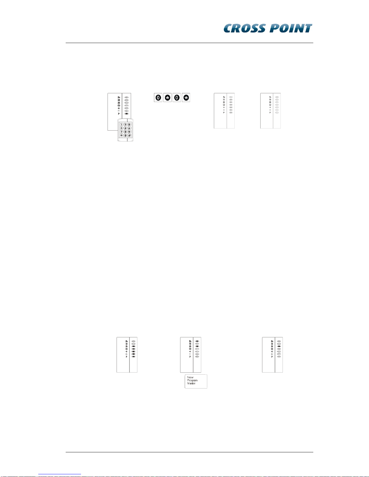
To set the user level, take the steps as mentioned in Figure 6.
1. Enter Program mode by
presenting the Installer
Remote Programmer
2. Press 0*0*
3. The XM3 goes to User
Sleep mode and switch
the power OFF.
Figure 6: Switch to User level
4.2.5 Learn the User Remote Programmer
To be able to program functions on the XM3 at User level, a User Remote
Programmer must be learned. To learn the User Remote Programmer, take
the steps as mentioned in Figure 7.
1. Power on from User Sleep
Mode
2. Present a second remote
programmer
3. Normal operation is
resumed.
Figure 7: Learn User Programmer
4.2.6 Set XM3 to sleep mode on User level
To proceed with the following steps, the XM3 must be set to User Sleep
mode first. To set the XM3 in User sleep mode, take the steps as mentioned
in Figure 8.
Configuring the XM3 11
1. Enter Program
mode by
presenting the
Installer remote
programmer
2. Enter 0*0* in
3. Level shown
4. Go to sleep mode
and Power OFF
Figure 8: Set User sleep mode
4.3 Configuring the XM3 using Master Cards
Master cards are standard cards that have been “promoted” to perform
certain management functions. Upon bringing the master card in the RF field
of an XM3, the master card can be used to perform its task. The use of the
Master Cards is explained in this manual.
The following masters are available:
Program master
Void master
Add Master
Night Lock master
Unlock master
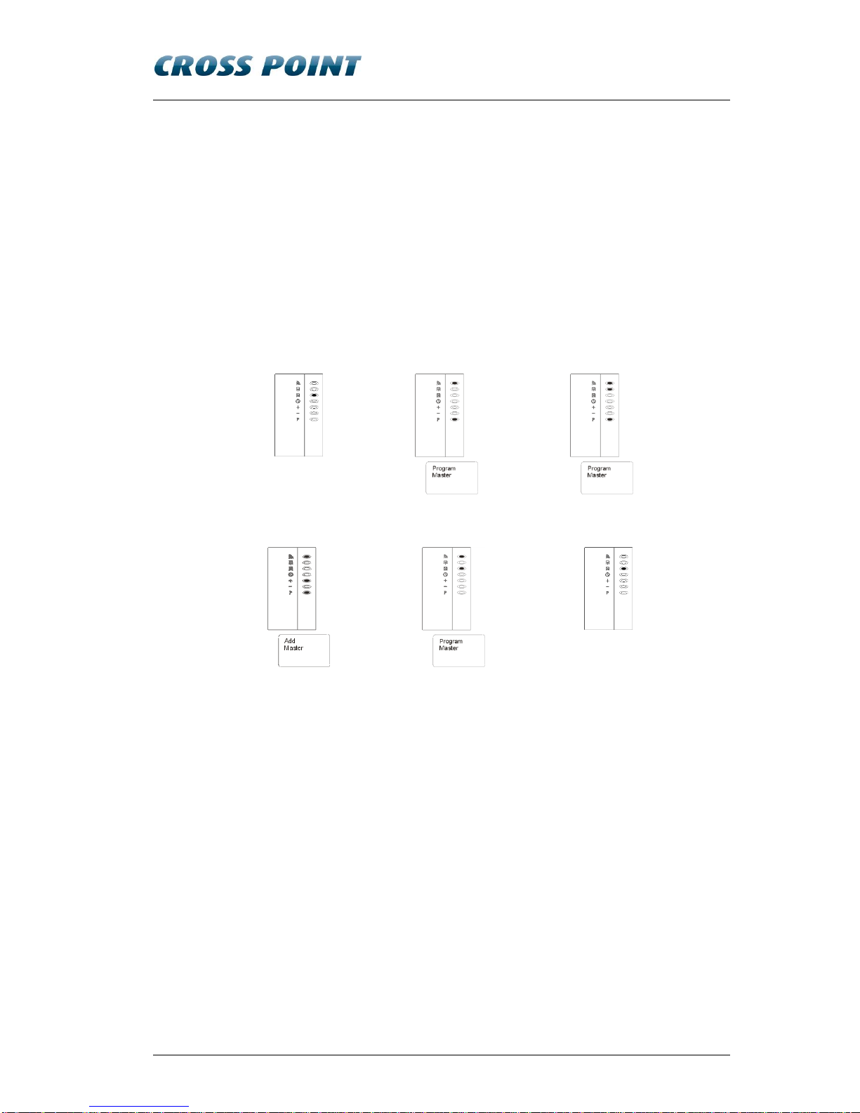
4.3.1 Learn the Program Master
To learn the Program Master, take the steps as mentioned in Figure 9.
NOTE To prevent tamper alarms, make sure the XM3 cover is placed.
1. Power on
2. Learn Program Master by
presenting it to the XM3
3. Normal operation of the XM3 is
resumed.
Figure 9: Learn Program Master

12 Configuring the XM3
4.3.2 Learn other Master Cards
Master cards are standard tags that have been
“promoted” to perform certain management functions.
Upon bringing the master card in the RF field of an
XM3, the master card can be used to perform its task.
The use of the Master Cards is explained in this Quick
Guide.
The following masters are available:
Program master
Void master
Add master
Night Lock master
Unlock master
Learning all Master Cards consists of the steps 1 up and including 8 as
mentioned in Figure 10. If you want to learn a certain Master Card, present
the Program Master to skip the steps that are not applicable to get to the step
where this Master Card can be learned. Learn the Master Card and present
the Program Master again to resume Normal operation.
For instance, you want to learn just the Add Master. You have to present the
Program Master 3 times to get to step 4, learn the Add Master and present
the Program Master 4 times to resume normal Operation.
NOTE Upon presenting the Program Master, a specific LED of the XM3 will go ON,
indicating which Master can be added.

Configuring the XM3 13
1. Enter program
mode by presenting
the Program
Master
2. Present Program
Master again and
the “-“ LED will go
ON indicating that
the Void Master
can be learned.
Proceed with step
3.
3. Present Void
Master to learn it to
the XM3 and the
“+” LED will go ON
indicating that the
Add Master can be
learned. Proceed
with step 4.
4. Present Add
Master to learn it
to the XM3 and
the “” LED will go
ON indicating
that the Night
Lock Master can
be learned.
Proceed with
step 5.
5. Present Night Lock
Master to learn it to
the XM3 and the “”
LED will go ON.
This LED has no
specific meaning
while learning
Master Cards.
Proceed with step
6.
6. Present program
master and the “”
LED will go ON to
indicate that the
Unlock Master can
be learned to the
XM3. Proceed with
step 7.
7. Present the Unlock
Master and the
learning process
automatically
finishes and normal
operation is
resumed (see step
8).
8. Normal operation
of the XM3 is
resumed.
Figure 10: Learn Master cards
14 Configuring the XM3
4.3.3 Set Open Time-out with Master Cards
Whenever access is granted, the relay of the XM3 will be activated during a
certain number of seconds, called the Open Time-Out.
This period of time can be adjusted from 1 to 255 seconds. The default value
is 2 sec, meaning that after presenting the tag to the XM3 reader, you have 2
seconds to open the door. If you want to use the default value, skip this step
and proceed with the next.
To use another setting than the default one, take the steps as mentioned in
Figure 11.
1. Normal
2. Program Master, enter
Program mode
3. Present Program Master
5x (skip steps)
4. Set Open Time-out to N
seconds: present Add
Master N* times
5. Program Master
6. Resume normal operation
*N= 1-255
Figure 11: Set Open Time-out with master cards

Configuring the XM3 15
4.3.4 Set Close Time-out with Master Cards
The XM3 has a special timer that is intended to check whether the gate or
door has been closed within a specific period of time.
This period of time is adjustable from 0 to 255 seconds. The default value is
“0”, meaning that the function is disabled. If you want to use the default
value, skip this step and proceed with the next.
NOTE I/O1 of the XM3 should be connected to ground or to ground via the door
switch when using this option. To use another setting than the default one,
take the steps as mentioned in Figure 12.
1. Normal
2. Program Master,
enter Program
mode
3. Present Program Master,
4x (skip steps)
4. Set Close Time-out to
0 seconds
5. Set Close Time-out to N
seconds: present Add Master
N* times
6. Program Master 2x (skip
steps), resume normal
operation
7. Resume normal operation
*N= 1-255
Figure 12: Set Close Time-out with master cards

16 Configuring the XM3
4.3.5 Adding cards with the Add Master Cards
If new cards must be part of your proximity system, the new cards must be
added to the XM3. An easy way to add cards is by using the Add Master. To
add cards with the Add Master cards, take the steps as mentioned in Figure
13.
NOTE A card that already has been learned to the XM3 or a card that cannot be
read correctly will cause the XM3 to generate an error.
1. Enter Add mode by
presenting Add Master
2. Add new User cards
(present each new card)
3. Present Add Master to resume
normal operation
Figure 13: Adding cards with the Add Master
4.3.6 Voiding cards with the Void Master
Using the Void Master is an easy way of removing cards from the XM3,
provided that the cards that have to be removed are available. Take the
steps as mentioned in Figure 14 to use the Void Master.
1. Enter Void mode by
presenting Add Master
2. Present the User card(s)
that need to be voided.
3. Present Void Master to resume
normal operation
Figure 14: Voiding cards with the Void Master
Other manuals for XM3 MICROPROXS
1
Table of contents
Popular Door Lock manuals by other brands


Philips
Philips EasyKey 9000 Series user manual

FingerTec
FingerTec ML-10B Admin & user guide

Trimco
Trimco 9 Series installation guide

schmersal
schmersal AZM 200 AS operating instructions

Assa Abloy
Assa Abloy effeff 118 Series manual

Assa Abloy
Assa Abloy Aperio C100 V3 Installation and mounting instructions

HES
HES KS100-640 Aperio installation instructions

Mardeco
Mardeco Groel Rose installation instructions

Corbin Russwin
Corbin Russwin Access 700 TCPAC1 Series installation instructions

Assa Abloy
Assa Abloy HES 9400 Installation Instructions and Frame Preparation

COX
COX Homelife Pairing Instructions

Sanela
Sanela SLZA 43A Mounting instructions