Crown CT33123 User manual


2
Content / Contenido / Содержание / Зміст / Мазмұны /
English
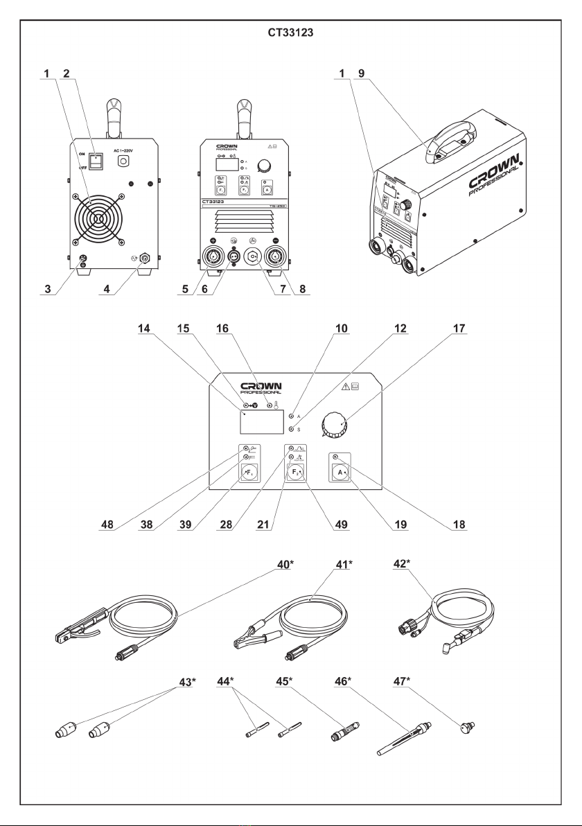
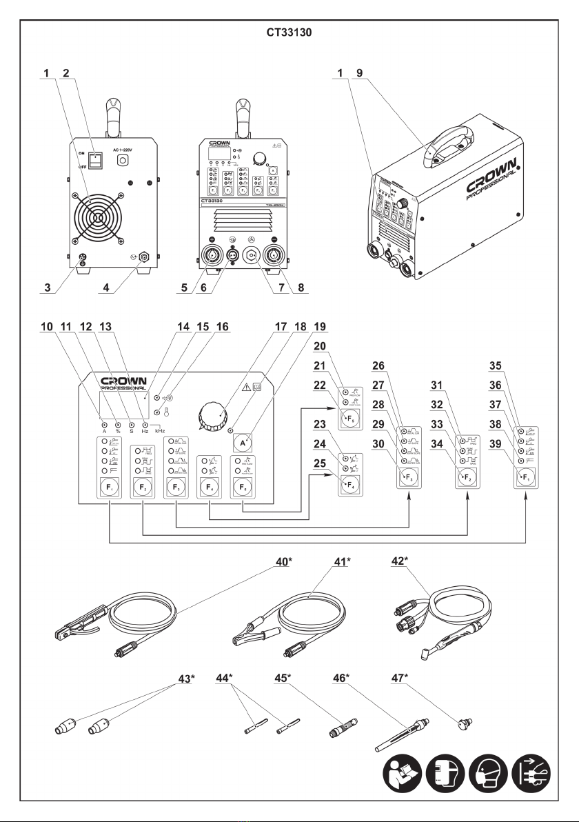
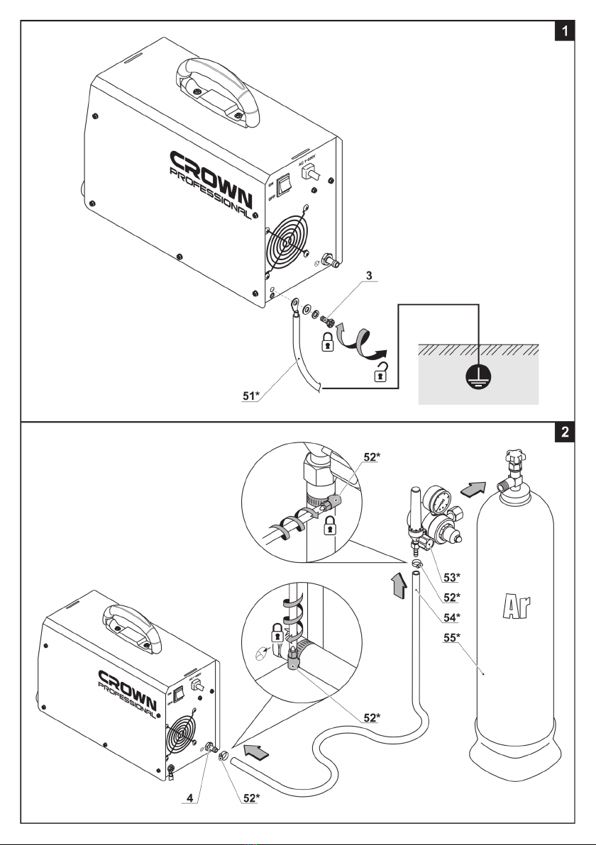
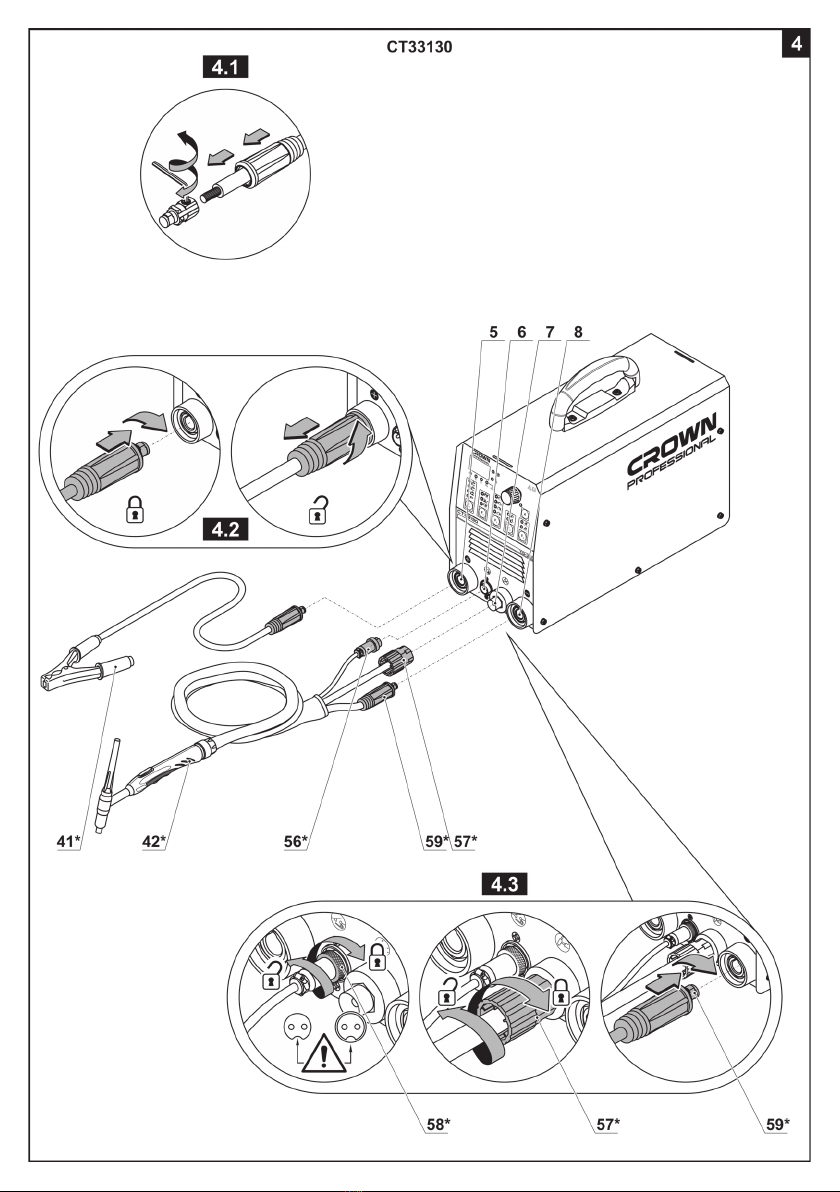
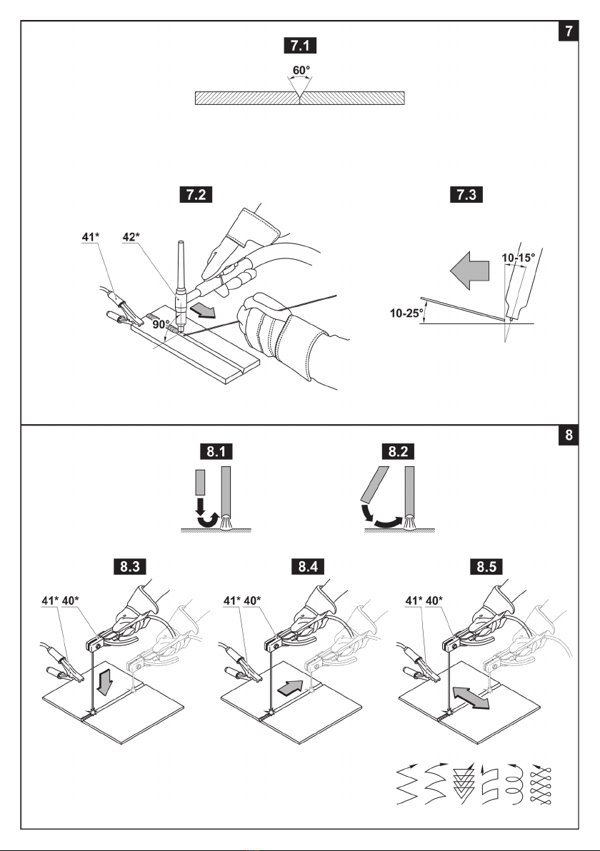
Explanatory drawings ������������������������������������������������������������������������������������������������������������ pages
General safety rules, instructions manual ����������������������������������������������������������������������������� pages
3 - 10
11 - 19
Español
Dibujos explicativos ������������������������������������������������������������������������������������������������������������ páginas
Recomendaciones generales de seguridad, manual de instrucciones ������������������������������ páginas
3 - 10
20 - 29
Русский
Пояснительные рисунки ������������������������������������������������������������������������������������������������ страницы
Общие указания по ТБ, инструкция по эксплуатации ������������������������������������������������� страницы
3 - 10
30 - 39
Украïнська
Пояснювальні малюнки ��������������������������������������������������������������������������������������������������� сторінки
Загальні вказівки по ТБ, iнструкція з експлуатації ��������������������������������������������������������� сторінки
3 - 10
40 - 49
Қазақ тілі
Түсіндіргіш әлеміштер �������������������������������������������������������������������������������������������������������� беттер
Жалпы қауіпсіздік жөніндегі ұсыныстар, пайдалану нұсқаулығы ���������������������������������������� беттер
3 - 10
50 - 59
����������������������������������������������������������������������������������������������������������������������������
����������������������������������������������������������������������������������������������������
3 - 10
60 - 68
�������������������������������������������������������������������������������������������������������������������������
��������������������������������������������������������������������������������������������
3 - 10
69 - 76

3

4

5

6

7

8

9

10

11
English
General safety recommendations
Safety instructions
These instructions contain important information which
either supplements or supersedes other instruction re-
lating to this product� Read these instructions carefully
before commencing operation�
Furthermore, the installation and use of the device
must follow the instructions given in the international
standard: IEC 60974-9 Arc welding equipment Part 9�
Installation and use
Use of personal protective equipment:
• The arc and its reecting radiation damage unpro-
tected eyes� Shield your eyes and face appropriately
before you start welding or observe welding� Also
note the different requirements for the darkness of the
screen in the mask as the welding current changes�
•The arc radiation and spatters burn unprotected
skin� Always wear protective gloves, clothing and foot-
wear when welding�
•Always wear hearing protection if the ambient noise
level exceeds the allowable limit�
General operating safety
•Exercise caution when handling parts heated in
welding� For example, the tip of the welding torch, the
end of the welding rod and the work piece will heat to
a burning temperature�
•Never carry the device or suspend it by the carrying
strap during welding�
•Do not expose the machine to high temperatures, as
this may cause damage to the machine�
•Keep the torch cable and earthling cable as close
to each other as possible throughout their length�
Straighten any loops in the cables� This minimizes
your exposure to harmful magnetic elds, which may
interfere with a pacemaker, for example�
•Do not wrap the cables around the body�
•In environments classied as dangerous, only use S-
marked welding devices with a safe idle voltage level�
These work environments include, for example, humid,
hot or small spaces where the user may be directly ex-
posed to the surrounding conductive materials�
•Do not use arc welding equipment for pipe thawing�
Spatter and re safety
•Welding is always classied as hot work, so pay atten-
tion to re safety regulations during welding and after it.
Machine specications
Inverter TIG welding machine CT33123 CT33129 CT33130
Machine code 425294 425300 425317
Rated input voltage [V] 1~ AC220 1~ AC220 1~ AC220
Rated frequency [Hz] 50 / 60 50 / 60 50 / 60
Rated input capacity
[TIG / MMA] [kVA] 7 / 8,2 7 / 8,2 7 / 8,2
Current adjustment range
[TIG / MMA] [A] 15-200 / 15-160 15-200 / 15-160 10-200 / 10-160
Rated output voltage
[TIG / MMA] [V] 10,8-18 / 20,6-26,4 10,6-18 / 20,6-26,4 10,4-18 / 20,4-26,4
No-load voltage [V] 95 95 95
Tungsten needle diameter
[TIG welding]
[mm]
[inches]
0,5 - 3,2
1/64" - 1/8"
0,5 - 3,2
1/64" - 1/8"
0,5 - 3,2
1/64" - 1/8"
Min. thickness of base metal
[TIG welding]
[mm]
[inches]
0,5
1/64"
0,5
1/64"
0,5
1/64"
Welding electrode diameter
[MMA welding]
[mm]
[inches]
1,6-4
1/16"-5/32"
1,6-4
1/16"-5/32"
1,6-4
1/16"-5/32"
Rated duty cycle (40°C) [%] 35 35 35
Efciency [%] ≥81 ≥81 ≥81
Weight [kg]
[lb]
7,7
16�98
7,7
16�98
7,7
16�98
Safety class IP21S IP21S IP21S
Insulation class HHH

12
English
• Remember that re can break out from sparks even
several hours after the welding work is completed�
•Protect the environment from welding spatter� Re-
move ammable materials, such as ammable uids,
from the welding vicinity and supply the welding site
with adequate reghting equipment.
•In special welding jobs, be prepared for hazards
such as re or explosion when welding container-type
work pieces�
•Never direct the spark spray or cutting spray of a
grinder toward the welding machine or ammable ma-
terials�
•Beware of hot objects or spatter falling on the ma-
chine when working above the machine�
• Welding in ammable or explosive sites is abso-
lutely forbidden�
General electric safety
•Only connect the welding machine to an earthed
electric network�
•Note the recommended mains fuse size�
•Do not take the welding machine inside a container,
vehicle or similar work piece�
•Do not place the welding machine on a wet surface
and do not work on a wet surface�
•Do not allow the mains cable to be directly exposed
to water�
•Ensure cables or welding torches are not squashed
by heavy objects and that they are not exposed to
sharp edges or a hot work piece�
•Make sure that faulty and damaged welding torches
are changed immediately as they can be lethal and
may cause electrocution or re.
•Remember that the cable, plugs and other electric
devices may be installed or replaced only by an electri-
cal contractor or engineer authorized to perform such
operations�
•Turn off the welding machine when it is not in use�
•In the case of abnormal behavior of the equipment,
such as smoke coming from the machine during nor-
mal use, take the machine to a CROWN service repre-
sentative for inspection�
Welding power circuit
•Insulate yourself from the welding circuit by using
dry and undamaged protective clothing�
•Never touch the work piece and welding rod, weld-
ing wire, welding electrode or contact tip at the same
time�
•Do not put the welding torch or ground cable on the
welding machine or other electric equipment�
•Turn off the machine from the main switch always
before you need to touch any components of the elec-
tric circuit, for example when replacing the electrode or
contact tip or moving the earth return clamp�
Welding fumes
•Ensure proper ventilation and avoid inhaling the
fumes�
•Ensure sufcient supply of fresh air, particularly in
closed spaces� You can also ensure the supply of clean
and sufcient breathing air by using a fresh-air mask.
•Take extra precautions when working on metals or
surface-treated materials containing lead, cadmium,
zinc, mercury or beryllium�
Transportation, lifting and suspension
•Pay attention to correct working position when lifting
a heavy device risk of injury to the back�
•Never pull or lift the machine by the welding torch
or other cables� Always use the lift points or handles
designed for that purpose�
•Only use a transport unit designed for the equip-
ment�
•Try to transport the machine in an upright position,
if possible�
•Never lift a gas cylinder and the welding machine at
the same time� There are separate provisions later for
gas cylinder transportation�
•Never use a welding machine when suspended un-
less the suspension device has been designed and ap-
proved for that particular purpose�
•It is recommended that the wire coil be removed dur-
ing lifting or transportation�
Environment
•The welding power source is not suitable for use in
rain or snow, although it can be used and stored out-
doors� Protect the equipment against rain and strong
sunlight�
•Always store the machine in a dry and clean space�
•Protect the machine from sand and dust during use
and in storage�
•The recommended operating temperature range
is -20°C to +40°C. The machine's operation efciency
decreases and it becomes more prone to damage if
used in temperatures in excess of 40°C�
•Place the machine so that it is not exposed to hot
surfaces, sparks or spatter�
• Make sure the airow to and from the machine is
unrestricted�
•Always use the machine in an upright position only�
•Arc welding equipment always cause electromag-
netic disturbance� To minimize the harmful effects of
this, use the equipment strictly according to the operat-
ing manual and other recommendations�
Gas cylinders and regulators
•Adhere to the instructions for handling gas cylinders
and regulators�
•Make sure that gas cylinders are used and stored
in properly ventilated spaces� A leaking gas cylinder
may replace the oxygen in the inhaled air, causing suf-
focation�
•Before use, make sure that the gas cylinder contains
gas suitable for the intended purpose�
• Always x the gas cylinder securely in an upright
position, against a cylinder wall rack or purpose-made
cylinder cart�
• Never move a gas cylinder when the ow adjuster
is in place� Put the valve cover in place during trans-
portation�
•Close the cylinder valve after use�
Circuit diagram and spare part lists
If the circuit diagram and the spare parts list are not in-
cluded in your delivery package, please request them
from your local CROWN service representative� For
more information, please visit www.crown-tools.com�

13
English
Disclaimer
While every effort has been made to ensure that the
information contained in this guide is accurate and
complete, no liability can be accepted for any errors
or omissions� CROWN reserves the right to change
the specication of the product described at any time
without prior notice�
Safety guidelines during machine opera-
tion
The operator or the machine's owner
shall be liable for the possible accidents
or damage that can be caused to the third
persons or their property.
Before starting the work
•Any operation of the machine with the damaged
or dismantled safety guards is prohibited� Never
operate the machine that is not properly assembled or
underwent the unapproved changes�
•The power network to which the machine is
connected must be equipped with safety devices or
the automatic circuit-breaker designed for current and
voltage matching the machine specications.
•The machine must be connected to the working
ground loop�
•The machine must be used in a vertical position
only - it must always rest on the rubber foots� Do not
put it down, suspend or put on end-faces�
•The machine is intended for continuous unattended
operation� Ensure that the machine is mounted far
from inammables and no external factors prevent
the normal cooling of the machine (free space around
machine must be no less than 50 cm)�
•The machine must not be used in the areas with
dust and containing explosive gases and vapours of
aggressive substances�
•Do not let small objects get into the machine - they
can disable it�
•Install the machine on a smooth, dry surface to
prevent tipping� Do not install the machine on a
vibrating surface�
•Carry the machine holding it only by its carrying
handle (handles) or a carrying belt� Pulling or lifting the
machine by a current-carrying, welding cable or gas
hose is strictly prohibited�
•It's necessary to ensure a proper ventilation of
workplace or to use special exhausts for removal of
fumes, formed during welding process�
•Follow precautions for storage, transportation and
usage of compressed gas cylinders:
•gas cylinders should be used and stored in proper
ventilated rooms;
•store a gas cylinder away from high-temperature
sources, protect it from direct sunlight;
•it is prohibited to move a shielding gas cylinder;
if it contains ow control valve, this valve should be
dismounted and valve cover should be installed;
•it's prohibited to lift simultaneously a gas cylinder
and a machine;
•transport cylinders by a special carriage;
•before use, please ensure that a gas cylinder
contains a gas relevant to work performed;
•protect cylinder against fall while using it, use
special legs, boxes, and x it with a lashing.
It is not recommended to stay close to
working machine for persons having
electronic cardiostimulators, due to a
danger of electromagnetic eld created,
which can cause its faulty operation.
During operation
•Observe the recommended machine time factor,
otherwise, the overload will result in the early wear of
its components thus reducing the machine service life�
•It is prohibited to expose the machine to rain or snow
and also use it in moist or humid environment�
•Don't point a welding torch to yourself, other people,
or animals�
•Don't touch a gas cylinder by tungsten electrode end
(if welding torch is turned on)�
•To avoid electrical shock do not touch machine
current-carrying elements�
•Do not touch the body of the connected machine
with wet hands, wet gloves or clothes�
•Do not get your body parts wound with welding
cables�
•Always switch off the machine when replacing an
electrode or shifting an earth clamp as well as moving
the machine�
•Never hold the running machine on your shoulder
and do not hang it on the carrying belt�
•Using the suspended machine except when a
suspension device has been specially designed for
this purpose is prohibited�
•The welding arch radiates bright visible light
beams both invisible ultra-violet and infra-red beams�
Inuence of light of an arch on the unprotected eyes
within 10-20 seconds in radius up to 1 meter from an
arch causes strong pains in eyes and a photophobia�
Longer inuence of light of an arch on the unprotected
eyes can result in serious diseases� Radiations of an
invisible spectrum cause burns on the unprotected
skin� Therefore it is forbidden to work without
a protective face shield, gloves and the special
clothes covering open skin.
•Observe rules and wear special protective clothes:
everything should be fully buttoned; valves of pockets
are to be let out; do not tuck a jacket in breeches, and
wear breeches atop a footwear�
•After operating do not touch the welding seam and
an area around it - you can be badly burnt�
•After operations the electrode end and torch ceramic
nozzle are hot, so manipulating with the electrode
(removal, replacement, etc�) should be done only in
protective gloves�
•Tungsten dust formed during electrode sharpening
is harmful (especially dust of tungsten electrodes
with additive of thorium), so always wear respiratory
protection during electrode end sharpening�
•Beware of ignition of surrounding objects due to
high temperature of a welding arch, or particles of the
melt metal� Remember, invisible design components
(wooden beams, insulation materials, etc�) can catch
re as well.
•Do not work next to highly inammable liquids,
gases and items (timber, paper, etc�)�
•Ensure, that incandescent items or weld spatter
don't fall on a machine, welding cables, gas hoses,
and gas cylinder�
•Be cautious when executing welding works on
capacities or pipelines in which combustible or toxic
substances were stored� Perform their decontamination

14
English
before the beginning of work; evaporations of
substances inside capacities or pipelines can cause
explosion, explosion or poisoning�
•Never execute welding works on the capacities
which are under pressure�
•Do not use the machine for defrosting frozen pipes�
•When working heights, observe safety procedure for
working heights�
After nishing operations
•Always turn off a gas cylinder valve after completion
of works�
•After the nal shut-off, examine a place where weld-
ing works were carried out, do not leave decaying sub-
jects, or the heated particles of metal - they can cause
a re.
•After nishing operation do not switch off the
machine at once, wait several minutes for the machine
to cool down sufciently.
Symbols used in the manual
Following symbols are used in the operation manual,
please remember their meanings� Correct interpreta-
tion of the symbols will allow correct and safe use of
the machine�
Symbol Meaning
Serial number sticker:
CT ��� - model;
XX - date of manufacture;
XXXXXXX - serial number�
Read all safety regulations
and instructions�
Wear a welding mask�
Wear a dust mask�
Disconnect the machine
from the mains before instal-
lation or adjustment�
Movement direction�
Rotation direction�
Symbol Meaning
Locked�
Unlocked�
Earthing loop�
Attention� Important�
Useful information�
Do not dispose of the ma-
chine in a domestic waste
container�
Machine designation
Machines are intended for creation of one-piece con-
nection of various metals (further in the text "welding of
metals") by their local fusion�
All models of welding inverter (TIG) allow welding
metals with direct current, with non-consumable elec-
trode (of tungsten) in an atmosphere of inert shielding
gases� Using this method, non-alloyed and low-alloyed
steel, stainless steel, copper, nickel, titanium, etc� can
be welded�
It is also possible to perform manual arc welding
(MMA) using consumable electrodes with coating�
Machine components
1 Ventilation hole
2 On / off switch
3 Ground bolt
4 Connecting pipe
5 Socket "+"
6 Welding torch control socket
7 Welding torch connector
8 Socket "-"
9 Carrying handle
10 Indicator "A" (current adjustment)
11 Indicator "%" (adjustment in parameters in per-
centage terms)
12 Indicator "S" (time adjustment)
13 "Hz-kHz" indicator (frequency adjustment)
14 Display
15 Power indicator
16 Temperature protection indicator

15
English
17 Regulator
18 Indicator "Current adjustment"
19 Button "A" (current adjustment)
20 Indicator "PRE FLOW" (gas purge time adjustment
before welding)
21 Indicator "POST FLOW" (gas purge time adjust-
ment after welding)
22 Button F5 (purge time adjustment)
23 Indicator "2T" (two-stroke torch operation mode)
24 Indicator "4T" (four-stroke torch operation mode)
25 Button F4 (torch operation mode selection)
26 Indicator "INITIAL CUR�" (adjustment of the start-
ing current)
27 Indicator "UP SLOPE" (adjustment of the current
increase time from the starting current to the op-
erating one)
28 Indicator "DOWN SLOPE" (adjustment of the
welding current decrease)
29 Indicator "CRATER CUR�" (adjustment of the cra-
ter lling current)
30 Button F3 (setting operating parameters for weld-
ing in a pulse mode)
31 Indicator "FREQ" (frequency adjustment when
working in a pulse mode)
32 Indicator "PEAK" (adjustment of the upper level
of the welding current when operating in a pulse
mode)
33 Indicator "BASE" (adjustment of the lower level
of the welding current when operating in a pulse
mode)
34 Button F2 (setting pulse mode parameters)
35 Indicator "LIFT TIG" (contact method for the arc
ignition)
36 Indicator "HF" (high-frequency method for the arc
ignition)
37 Indicator "Pulse mode"
38 Indicator "MMA welding"
39 Button F1 (welding method selection)
40 Electrode holder (assembled) *
41 Earth clamp (assembled) *
42 Torch *
43 Ceramic nozzle of the torch *
44 Collet *
45 Collet holder *
46 End cap (long) *
47 End cap (short) *
48 Indicator "TIG welding"
49 Button F2 (adjustment of the welding current de-
crease time / adjustment of the gas purge time
after welding)
50 Button "MMA welding"
51 Ground wire *
52 Clamp *
53 Gas pressure regulator with a gas ow regulator *
54 Hose *
55 Gas cylinder (argon) *
56 Torch control cable *
57 Connector of the torch connection cable *
58 Nut of the torch control cable connector *
59 Power connector of the torch *
60 Torch body *
61 Tungsten electrode *
* Optional extra
Not all of the accessories illustrated or described
are included as standard delivery.
Installation and regulation of machine
elements
Before carrying out any works on the machine it
must be disconnected from the mains.
Do not draw up the fastening ele-
ments too tight to avoid damaging the
thread.
Mounting / dismounting / setting-up of
some elements is the same for all ma-
chine models, in this case specic mod-
els are not indicated in the illustration.
Mounting / dismounting of a plug, current-carrying
cable, stationary network connection
Some machine models are supplied without plugs
and / or current-carrying cables - they must be installed
before the beginning of the operation�
Machines can also be connected to the network on a
stationary basis (not through a socket)�
Note: the stationary connection of the
machine to the network as well as instal-
lation or replacement of current-carrying
cables, plugs and other electrical units
must be performed only by a qualied electrician or
circuit installer authorized to perform such works.
Connection to the earthing loop (see g. 1)
Using grounding bolt 3connect one grounding wire
clamp 51 to the machine (see g. 1). Connect the sec-
ond grounding wire clamp 51 to the working grounding
loop�
Gas connection (see g. 2)
•Install a gas pressure regulator 53 on a gas cylin-
der 55 (see g. 2). Attention: ow rate meter ask
should be installed vertically upward.
•Put clamps 52 on the ends of hose 54� Connect one
end of the hose 54 to a connection pipe of the gas
pressure regulator 53, the other one - to the connec-
tion pipe 4� Fix the hose 54 on connection pipes by
clamps 52�
Connecting / disconnecting welding cables (see
g. 3-5)
During TIG welding (see g. 3-4)
•If necessary to attach the connector to the welding
cable, follow the steps shown in g. 3.1, 4.1.
•If electrode holder 40 is installed, disconnect it�
•Connect earth clamp 41 (see g. 3.2, 4.2) to the ma-
chine�
•Connect the welding torch 42 to the machine:
•connect a welding torch control cable� Set a con-
trol cable connector in socket 6and tighten a nut 58
by hand� During installation, pay attention that locat-
ing tab inside of a socket ts a location slot of the
cable connector (see g. 3.3, 4.3);

16
English
•put the screw nut 57 on the connector thread 7
(see g. 3.3), and tighten it manually;
•only for model CT33130 - connect power con-
nector 59 to socket "-" 8 (see g. 4.3).
•Disconnect all cables in reverse sequence�
During MMA welding (see g. 5)
•If welding torch 42 is installed, disconnect it�
•If necessary to attach the connector to the welding
cable, follow the steps shown in gure 5.1.
•Insert plugs of the welding cables to the machine
as shown on gure 5.2. When connecting, please
observe the recommended polarity�
•Disconnect plugs of the welding cables in a reverse
order (see g. 5.3)�
Welding torch assembly / disassembly / setting
process (see g. 6)
•A ceramic torch nozzle 43 is chosen on the basis of
actual operation recommendations�
•When installing a tungsten electrode 61, please
ensure that it's properly sharpened (see g. 6.4-6.6
and recommendations below)�
•Collet 44 inside diameter should be relevant to a
diameter of tungsten electrode 61�
•In order to perform works in tight areas, you may
install a short end cap 47, as illustrated on g. 6.2 (in
this case, please use the tungsten electrode 61 of a
proper length)�
•Screw the collet holder 45 and ceramic torch noz-
zle 43 into the welding torch body 60 (see g. 6.1-6.2).
•Put the collet 44 on the tungsten electrode 61 and
insert it into the collet holder 45�
•Adjust the distance for which tungsten electrode 61
protrudes from the ceramic nozzle 43� Normally, out-
let of the tungsten electrode 61 from a ceramic torch
nozzle 43 is 2-3 mm (see g. 6.3); however it can run
to 8 mm during angular welding�
•Screw the end cap 46 or 47 into the welding torch
body 60 (see g. 6.1-6.2).
•Dismantle in reverse order�
Initial operating of the machine
Before starting the operation the following steps are
necessary:
•always use the correct supply voltage: the power
supply voltage must match the information quoted
on the machine body;
•inspect the condition of all cables and replace the
cable where damage is found;
•inspect the condition of hose 54, replace it if dam-
age is found;
•please ensure that there is no gas leakage when
turning on the gas;
•inspect the condition of welding torch 42 (dur-
ing TIG welding), electrode holder 40 (during MMA
welding), and earth clamp 41, replace it if damage
is found;
•inspect the tungsten electrode sharpening ac-
curacy (during TIG welding) and a distance it over-
hangs a welding torch ceramic nozzle�
•Before starting the machine, make sure that elec-
trode and earth clamp 41 don't touch each other�
•After the machine is switched on, make sure that the
built-in cooling fan is working - the air will be blowing
from vent holes 1(on the back of the machine)�
Switching the machine on / off
Switching on:
Move switch 2into the "On" position (indicator 15 will
then light up and the built-in cooling fan will start rotat-
ing)�
Switching off:
Move switch 2into the "Off" position�
Design features of the machine
Buttons and indicators of the front panel
Temperature protection
Temperature protection prevents machine damage,
switching it off in case of overheating� When tempera-
ture protection goes on, indicator 16 lights up� Do not
switch the machine off, let it cool down and do not con-
tinue operation until then�
Power indicator
Power indicator 15 is on when the machine is
connected to the mains and is ready to be switched on�
Easy start
Only for welding in the MMA mode. The easy start
function (increased voltage of idle running) facilitates
the lighting up of the welding arc�
[CT33123]
F1 button (welding method selection)
Press button 39 (F1) to select one out of two welding
methods:
•TIG welding (welding with a non-consumable
electrode in an inert shielding gas medium with a
high-frequency method of arc ignition) - when this
mode is selected, indicator 48 is lit and the welding
current can be adjusted (see below);
•MMA welding (manual arc welding with
consumable electrodes with coating) - when this
mode is selected, indicator 38 is lit and the welding
current can be adjusted (see below)�
F2 button (adjustment of the welding current
decrease time / adjustment of the gas purge time
after welding)
TIG welding only� Press button 49 (F2) to select the
mode to adjust the welding current reduction time or
gas purge time after welding:
•mode to adjust the welding current decrease
time (DOWN SLOPE) - gradual reduction of the
welding current ensures high-quality crater welding
at the end of the welding seam)� When this mode is
selected, indicators 28 and 12 are lit� To change the
time, turn regulator 17 (the set value will be shown
on display 14);

17
English
•mode to adjust the gas purge time after welding
(POST FLOW) - when welding is nished, gas purge
allows the end of the welding seam to cool down
gradually, prevents cracking and the formation of
oxides� When this mode is selected, indicators 21
and 12 are lit� To change the time, turn regulator 17
(the set value will be shown on display 14)�
Button A (welding current adjustment)
Button 19 (A) allows to switch between the time
adjustment (F2 button, see above) and the welding
current adjustment for both TIG and MMA welding
modes� In the mode to adjust the welding current,
indicators 10 and 18 are lit; to change the welding
current, turn regulator 17 (the set value will be shown
on display 14)� The magnitude of the welding current
depends on the works performed, thickness of
workpieces to be welded, an electrode diameter, etc�
[CT33129]
Button "MMA welding"
Press button 50 to select one out of two welding meth-
ods:
•TIG welding (welding with a non-consumable
electrode in an inert shielding gas medium with a
high-frequency method of arc ignition) - when this
mode is selected, indicator 38 is not lit, welding
current can be adjusted (see below);
•MMA welding (manual arc welding using
consumable electrodes with coating) - when this
mode is selected, indicator 38 is lit, welding current
can be adjusted (see below)�
Welding current adjustment
To change the welding current, turn regulator 17 (the
set value will be shown on display 14)� The welding
current magnitude depends on the works performed,
thickness of workpieces to be welded, an electrode
diameter, etc�
[CT33130]
F1 button (welding method selection)
Press button 39 (F1) to select a welding method:
•LIFT TIG (non-consumable electrode welding
in an inert shielding gas medium with a contact
method of arc ignition) - when this mode is selected,
indicator 35 is lit;
•HF TIG (non-consumable electrode welding in an
inert shielding gas medium with a high-frequency
method of arc ignition) - when this mode is selected,
indicators 35 and 36 are lit;
•PULSE TIG (non-consumable electrode welding
in an inert shielding gas medium in a pulse mode;
in this mode the workpiece heating and distortion
during welding are reduced; it is suitable for welding
thin workpieces or decorative welding) - when this
mode is selected, indicators 35 and 37 are lit;
•MMA welding (manual arc welding using
consumable electrodes with coating) - when this
mode is selected, indicator 38 is lit�
F2 button (setting pulse mode parameters)
Only for welding in the PULSE TIG mode� Press
button 34 (F2) to set pulse mode parameters:
•frequency control mode (FREQ) - when this mode
is selected, indicators 31 and 13 are lit� To change
this parameter, turn regulator 17 (the set value will
be shown on display 14, when the frequency is set
to more than 999 Hz, display 14 will show values in
kHz, and indicator 13 will blink);
•mode to adjust the upper level of the welding
current (PEAK) - when this mode is selected, indi-
cators 32 and 11 are lit� To change this parameter,
turn regulator 17 (the set value will be shown on dis-
play 14);
•mode to adjust the low level of the welding cur-
rent (BASE) - when selecting this mode, indica-
tors 33 and 11 are lit� To change this parameter,
turn regulator 17 (the set value will be shown on
display 14)�
Button F3 (setting operating parameters for pulse
welding)
Only for welding in the PULSE TIG mode and four-
stroke torch operation mode (4T). Press button 30
(F3) to adjust operating parameters for pulse welding:
•starting current adjustment mode (INITIAL CUR) -
when this mode is selected, indicators 26 and 10 are
lit� To change this parameter, turn regulator 17 (the
set value will be displayed on display 14);
•mode to adjust the time for increasing the cur-
rent from the starting current to the operating one
(UP SLOPE) - when selecting this mode, indica-
tors 27 and 12 are lit� To change this parameter,
turn regulator 17 (the set value will be shown on
display 14);
•mode to adjust the welding current reduction time
(DOWN SLOPE) - when this mode is selected, indi-
cators 28 and 12 are lit� To change this parameter,
turn regulator 17 (the set value will be shown on dis-
play 14);
•mode to adjust the crater lling current (CRATER
CUR) - when this mode is selected, indicators 29
and 10 are lit� To change this parameter, turn regula-
tor 17 (the set value will be shown on display 14)�
F4 button (torch mode selection)
TIG welding only� Press button 25 (F4) to select one
out of two operating modes of torch 42:
•2T mode (two-stroke, when this mode is selected,
indicator 23 is lit) - press and hold torch 42 button to
turn it on� During operation, keep holding torch 42
button in a pressed position� To turn off, release
torch button 42;
•4T mode (four-stroke, when this mode is selected,
indicator 24 is lit) - press and release torch 42 button
to turn it on� During operation, do not hold torch 42
button in a pressed position� To turn off, press and
release torch 42 button�
F5 button (purge time adjustment)
TIG welding only� Press button 22 (F2) to select the
gas purge time before or after welding:
•mode to adjust the gas purging time before
welding (PRE FLOW) - gas purging before welding
allows the air to be displaced from a welding area to
prevent the formation of oxides� When this mode is
selected, indicators 20 and 12 are lit� To change this
parameter, turn regulator 17 (the set value will be
shown on display 14);

18
English
•mode to adjust the gas purging time after welding
(POST FLOW) - gas purging after welding allows
the end of the welding seam to cool down gradually,
preventing cracking and the formation of oxides�
When this mode is selected, indicators 21 and 12
are lit� To change this parameter, turn regulator 17
(the set value will be shown on display 14)�
Button A (welding current adjustment)
Button 19 (A) allows to switch from the adjustment of
other parameters to the welding current adjustment for
both the TIG and MMA welding modes� In the welding
current adjustment mode, indicators 10 and 18 are
lit� To change this parameter, turn regulator 17 (the
set value will be shown on display 14)� The welding
current magnitude depends on the works performed,
thickness of workpieces to be welded, an electrode
diameter, etc�
Recommendations on the machine op-
eration
Preliminary works (see g. 7)
•Clean welding surfaces from rust and paint coatings�
•The edges of pieces to be welded should be ma-
chined if welding blanks width is more than 1 mm (see
g. 7.1).
•Please remember that a large quantity of heat is
released during welding which can damage the sur-
rounding items, therefore, carefully choose the site
and take appropriate actions to prevent re.
Electrodes
The right choice of electrodes, to a great extent, pre-
determines the welding seam quality and the operation
speed� Before purchasing electrodes, carefully
examine the recommendations of their use� Consult a
specialist if necessary� It is also important to observe
the electrode storage conditions�
General operation recommendations
The recommendations below apply to all
machines connected through a socket
connector. In the case of stationary con-
nection the machine assembly and net-
work connection will be done beforehand.
•Place the machine in an even, dry, not vibrating
surface observing all above-mentioned safety proce-
dures�
•Connect the ground wire�
TIG welding (see g. 7)
•Connect gas feeding, earth terminal cable, and
welding torch to the machine� Connect earth clamp 41
to socket "+" 5�
•Fix earth clamp 41 on one of the parts to be weld-
ed�
•Connect the machine to the mains and switch it on�
•Select the TIG welding mode as described above�
•Slightly open the valve of gas pressure regulator 53
and turn on the valve of gas cylinder 55� Push and
hold button of welding torch 42, gas will come from a
ceramic torch nozzle 43; using the valve of gas pres-
sure regulator 53, set gas ow rate (l/min), necessary
for work performance; release the button of welding
torch 42�
•Set the welding current value�
•Adjust other process parameters as described
above, if necessary�
•Turn on welding torch 42 (as described above) and
light the arc:
•for the high-frequency ignition of the arc, bring
torch 42 to workpieces to be welded and hold it so
that the distance between tungsten electrode 61 and
a workpiece is 2-4 mm - a high-frequency discharge
will ignite the welding arc;
•for the contact ignition of the arc, touch the
workpiece with an end of tungsten electrode 61,
then slightly tilt and raise torch 42 until a 2-3 mm gap
forms between a tip of tungsten electrode 61 and the
workpiece - at this moment a welding arc will form�
•If you weld workpieces thicker than 1 mm, a rod of
proper diameter should be fed in arc burning area for
lling a welding seam.
•Hold welding torch 42 and a rod, as illustrated in
gures 7.2 and 7.3 (grey arrow shows a direction of
welding torch movement)� Move the welding torch 42
and rod along a welding seam, delivering a ller rod, as
it's consumed, in welding point�
•After completion of welding, release the button of
welding torch 42, but don't remove it, wait for crater lling
and cooling down of the shielding gas welding end�
•After completion of work, machine should cool down,
then disconnect it and close valve of gas pressure
regulator 53 and valve of gas cylinder 55�
MMA welding (see g. 8)
When describing MMA welding, elec-
trodes mean stick consumable elec-
trodes having coatings.
•Connect the welding cables to the machine� Weld-
ing can be performed with direct and reverse polarity�
The selection of polarity depends on the materials to
be welded and the recommendations on how to use
electrodes�
•Direct polarity - connect electrode holder 40 to
socket "-" 8, connect earth clamp 41 to socket "+" 5�
In such a mode the electrode heats less than the
basic metal, the electrodes get fused slower, the
welding joint is completed with a deeper penetration�
•Reverse polarity - connect electrode holder 40 to
socket "+" 5, connect earth clamp 41 to socket "-" 8�
In such a mode the work piece is heated less than
the electrode which can be used for welding high-
carbon, alloy and special steels sensitive to over-
heat as well as for welding sheet metal�
•Press the lever of the electrode holder 40 and install
the electrode end (the end free from coating) into elec-
trode holder 40 and then release the lever�
•Fix earth clamp 41 on one of the parts to be welded�
•Connect the machine to the mains and switch it on�
•Select the MMA welding mode as described above�
•Set the welding current value� The selection of
welding current depends on the electrode to be used,
thickness of material to be welded, spatial position of
a seam etc�
•Ignite the welding arc in one of two ways: ignition
by touching (see g. 8.1); ignition by scratching (see
g. 8.2).

19
English
•The main practices of welding electrode handling
are described below:
•usually welding is carried out with vertically po-
sitioned electrode or at its inclination concerning a
seam, in a corner forward or back� When welding by
a corner back, it is provided better fusion and smaller
width of a seam (but performance of work in this case
demands the certain skill);
•progressive motion of an electrode (see
g. 8.3) - on a direction of an axis of the electrode, for
maintenance of necessary arch length which should
make 0,5-1,1 of electrode diameter� The length of an
arch renders the serious inuence on quality of a weld-
ed seam and its form� A long arch causes intensive oxi-
dation and nitration of the fused metal, and increased
splashing of it;
•longitudinal movement of an electrode (see
g. 8.4) - for formation of a welded seam� Speed of
movement of an electrode depends on electric current,
electrode's diameter, type and spatial position of a seam;
at the high speed of an electrode the basic metal
has no time for fusion, what results in insufcient
depth of weld fusion spill is formed;
insufcient speed of moving of an electrode re-
sults in overheating and arc burn (through fusion)
of metal;
correctly chosen speed of longitudinal movement
along an axis of a welded seam allows obtaining its
width on 2-3 mm more than diameter of an electrode;
•lateral movement of an electrode (see g. 8.5) -
for formation of the widened welded seam� An elec-
trode is moved in lateral oscillatory movements more
often with constant frequency and the amplitude,
combined with progressive motion of an electrode
along an axis of the prepared groove, and to an axis
of an electrode� Lateral oscillations of an electrode
are various and are determined by the form, the
sizes, positions of a seam in space in which welding
is carried out, and skill of the welder� The width of
a welded seam in this case should not exceed 2-3
diameters of an electrode�
•Watch the electrode length and when 20-30 mm is left
to the electrode holder 41 jaws - replace the electrode�
•Wait for cooling down and crystallization of slag on
a welding seam upon which remove the slag using a
special hammer and a brush� You must wear protective
gloves or a mask when performing these operations�
•Check the welding seam quality and when the faults
are found remove them�
•Following the completion of work, let the machine
cool down, switch it off and then disconnect the cables�
Machine maintenance / preventive meas-
ures
Before carrying out any works on the machine it
must be disconnected from the mains.
Electrode sharpening (see g. 6.4-6.6)
Operations for non-consumable elec-
trodes (of tungsten or tungsten with ad-
ditives) only are described below.
Electrode end contamination or damage is made
because of touching the weld pool metal or a ller rod
by electrode, as well as because of a wrong selection
of shielding gas quantity, delivered to welding area�
The electrode should be sharpened properly and
timely�
During alternating current welding the electrode end
should be put into semi-spherical shape (see g. 6.4).
During direct-current welding the electrode end should
be put into conical shape� In general, sharpening cone
should be 2-2,5 of electrode diameters in length, a
sharpening angle should be 14°-60°� Sharpening cone
angle impact on arc form and metal penetration is
shown in gure 6.4.
Using the electrode with pointed end, weld very thin
metals (0,125-1 mm)� Welding thicker metal, blunt the
electrode end, otherwise it melts and tungsten enters
the welding seam�
Sharp the tungsten electrode axially, using a special
ne abrasive disk. Perform grinding operation in
direction of electrode length (see g. 6.5).
Don't sharpen the tungsten electrode as illustrated
in figure 6�6, it will result in unstable arc, it will im-
pair welding seam quality and make arc striking dif-
ficult�
Cleaning of the machine
An indispensable condition for a safe long-term ex-
ploitation of the machine is to keep it clean� Regularly
ush the machine with compressed air thought the
vent holes 1�
After-sales service and application service
Our after-sales service responds to your questions
concerning maintenance and repair of your product as
well as spare parts� Information about service centers,
parts diagrams and information about spare parts can
also be found under: www.crown-tools.com�
Transportation of the machine
•Categorically not to drop any mechanical impact on
the packaging during transport�
•When unloading / loading is not allowed to use any
kind of technology that works on the principle of clamp-
ing packaging�
Environmental protection
Recycle raw materials instead of dispos-
ing as waste.
Machine, accessories and packaging
should be sorted for environment-friendly
recycling�
The plastic components are labelled for categorized
recycling�
These instructions are printed on recycled paper man-
ufactured without chlorine�
The manufacturer reserves the possibility to introduce changes.

20
Español
Recomendaciones generales de seguri-
dad
Instrucciones de seguridad
Estas instrucciones contienen información importante
que complementa o reemplaza otras instrucciones re-
lacionadas con este producto� Lea estas instrucciones
cuidadosamente antes de comenzar a operar el pro-
ducto�
Además, la instalación y el uso del aparato debe se-
guir las instrucciones dadas en la norma internacional:
equipo para soldar de arco IEC 60974-9 Pieza 9�
Instalación y uso
Uso de equipo de protección personal:
•El arco y su radiación reectante dañan los ojos
que no están protegidos� Antes de comenzar a
soldar o de observar cómo se suelda, cúbrase los
ojos y el rostro� Tenga en cuenta también los dis-
tintos requisitos para la oscuridad de la pantalla en
la máscara a medida que cambia la corriente de la
soldadura�
•La radiación del arco y las esquirlas queman la piel
que no está protegida� Use siempre guantes, ropa y
calzado protector cuando suelde�
•Use siempre protección para los oídos si el nivel de
ruido ambiente excede el límite permitido�
Seguridad general en el funcionamiento
•Tenga cuidado cuando manipula piezas calientes de
la soldadura� Por ejemplo: la punta del soplete para
soldar, el extremo de la varilla para soldadura y la pie-
za de trabajo se calentarán hasta alcanzar una tempe-
ratura que provoque quemaduras�
•Nunca lleve el aparato ni lo cuelgue de la correa de
transporte mientras está soldando�
•No exponga la máquina a altas temperaturas, ya
que esto puede causar daño a la máquina.
•Mantenga el cable del soplete y el cable de descar-
ga a tierra tan cerca uno del otro como sea posible
en toda su longitud� Enderece cualquier bucle en los
cables� Esto minimiza su exposición a campos magné-
ticos nocivos, que pueden interferir, por ejemplo, con
un marcapasos�
•No envuelva los cables alrededor del cuerpo�
• En entornos calicados como peligrosos, utilice sólo
dispositivos de soldadura marcados con la letra S,
Características de la máquina
Máquina de soldar TIG Inversora CT33123 CT33129 CT33130
Código de la máquina 425294 425300 425317
Voltaje nominal de entrada [V] 1~ AC220 1~ AC220 1~ AC220
Frecuencia nominal [Hz] 50 / 60 50 / 60 50 / 60
Capacidad nominal de entrada
[TIG / MMA] [kVA] 7 / 8,2 7 / 8,2 7 / 8,2
Campo de regulación de corriente
[TIG / MMA] [A] 15-200 / 15-160 15-200 / 15-160 10-200 / 10-160
Voltaje nominal de salida [TIG / MMA] [V] 10,8-18 / 20,6-26,4 10,6-18 / 20,6-26,4 10,4-18 / 20,4-26,4
Voltaje sin carga [V] 95 95 95
Diámetro de aguja de
tungsteno [soldadura TIG]
[mm]
[pulgadas]
0,5 - 3,2
1/64" - 1/8"
0,5 - 3,2
1/64" - 1/8"
0,5 - 3,2
1/64" - 1/8"
Espesor mínimo del metal
base [soldadura TIG]
[mm]
[pulgadas]
0,5
1/64"
0,5
1/64"
0,5
1/64"
Ø electrodos de soldadura
[soldadura MMA]
[mm]
[pulgadas]
1,6-4
1/16"-5/32"
1,6-4
1/16"-5/32"
1,6-4
1/16"-5/32"
Ciclo de trabajo nominal (40°C) [%] 35 35 35
Eciencia [%] ≥81 ≥81 ≥81
Peso [kg]
[lb]
7,7
16�98
7,7
16�98
7,7
16�98
Clases de protección IP21S IP21S IP21S
Clase de aislamiento HHH
This manual suits for next models
2
Table of contents
Languages:
Other Crown Welding System manuals
Popular Welding System manuals by other brands

Miller
Miller TRAVEL MAASTER SPT-1C owner's manual

Sealey
Sealey SUPERMIG230 instruction manual

Hwayuan Electric
Hwayuan Electric ZX7-315IGBT Operator's manual

Chicago Electric
Chicago Electric 98870 Set up and operating instructions

Top Gun
Top Gun SYN 2500 PULSE user manual

Bug-O Systems
Bug-O Systems GO-FER III-OX Instructions and parts manual

Blue Demon
Blue Demon BlueArc 160STI owner's manual

DNIPRO M
DNIPRO M SAB-17DX Instructions for operation

McElroy
McElroy T-500 I Series manual

Costway
Costway GoPlus EP24430 user manual

Lincoln Electric
Lincoln Electric CLASSIC 300 D PERKINS Brochure & specs

Paton
Paton StandardMIG-160 Data sheet and operating manual