Crystal GauGeCaLXP User manual
Service Instruction Sheet
Introduction
These instructions are intended for use with comparator rebuild kit (PN 3143). Rebuild kit 3143 con-
tains all of the parts and tools required to rebuild the GaugeCalXP™pressure comparator. Rebuilds
should be performed only by qualied personnel.
Service Instructions
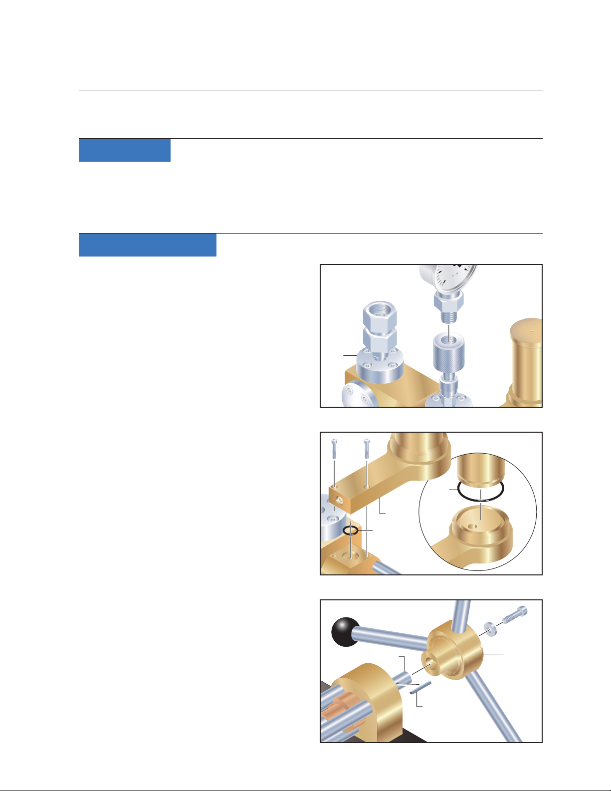
1Remove all gauges from the GaugeCalXP
pressure comparator (gure 1).
2Tip the comparator on its end to completely
drain the water, oil, or isopropyl alcohol from
the system. Always dispose of uids in a
responsible manner.
3Use a 3mm Allen key to remove the two (2)
cap screws securing the Reservoir to the
Main Seal Block, then lift to remove the Res-
ervoir and Reservoir o-ring (PN 2018)
(gure 2).
4Remove the press-t Reservoir Vessel,
and replace the lower seal o-ring (PN 3303
or PN 3376) (gure 2).
*Note:The GaugeCalXP is assembled with
a Reservoir o-ring in one of two sizes. Com-
pare your o-ring to the illustrated parts list
on page 6, to determine the appropriate
replacement size for your unit.
5Use a 5mm Allen key to remove the Handle
Assembly cap screw and washer, then pull to
slide the Handle Assembly from the Piston
Assembly (gure 3). Be sure to also remove
the Key from the Piston Assembly Leadscrew
(gure 3).
PRESSURE COMPARATOR
10000PSI–700bar
Gau
G
eCa
LXP
XP™
Figure 1
Figure 2
Figure 3
C R Y S T A L
engineering corporation
PSI
50
0300
Gauge
Base
Reservoir
O-ring(PN 2018)
O-ring
(PN 3303)
(PN 3376)
or *
Handle
Key
Leadscrew

Page 2 •GaugeCalXP Service Instruction Sheet
C R Y S T A L
engineering corporation
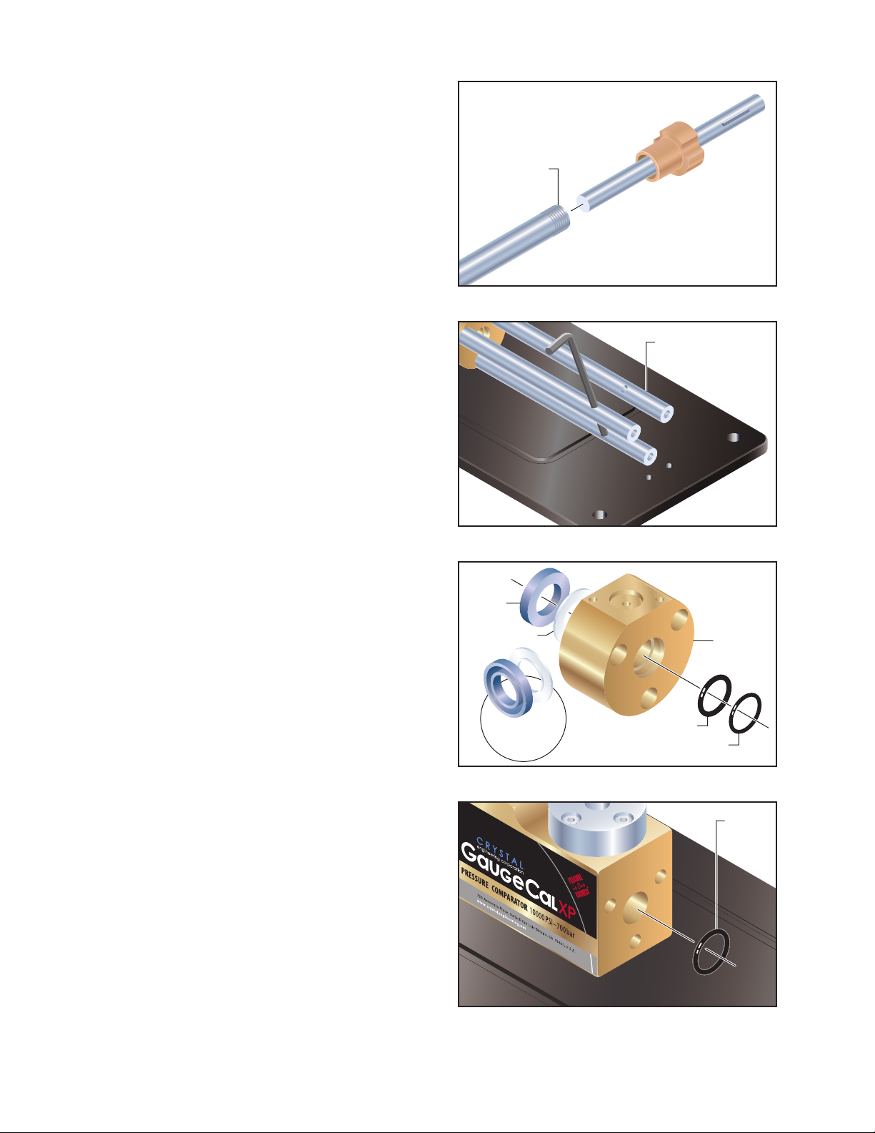
6Turn the comparator over to gain access to
the underside of the Baseplate.
Be aware that water or other test uid may
still be present in the system, and may drain
out as the comparator is turned over.
7Use a 4mm Allen key to remove the two (2)
cap screws holding the Bearing Block to the
Baseplate (gure 4).
8Turn the comparator back over, and then use
a 5mm Allen key to remove the three (3) cap
screws from the front of the Bearing Block
(gure 5).
9Carefully pull to slide the Bearing Block and
Piston Assembly from the Manifold Block
and Baseplate, taking care to avoid making
contact with the three guide rods (gure 6).
10 Pull to slide the Piston Assembly from the
rear of the Bearing Block, and then remove
the Bearing Ring and Bearing Washer from
the front of the Leadscrew (gure 7).
11 Unscrew the Piston Shaft from the Piston
Assembly for cleaning, and then apply a
light coat of grease before reassembling
(gure 8).
Note: The Piston Shaft has a left-hand
thread, so you will turn it clockwise to
remove it, and then counter-clockwise to
replace it.
Figure 4
Figure 5
Figure 6
Figure 7
Bearing Block
Baseplate
Piston
Assembly
Guide
Rod
Bearing
Washer
Bearing
Ring
Leadscrew
GaugeCalXP Service Instruction Sheet •Page 3
C R Y S T A L
engineering corporation
12 To remove the three (3) stainless steel Guide
Rods, insert the 4mm Allen key into the hole
in the side of each rod, and then pull to the
left (counter-clockwise) to loosen and un-
screw each one (gure 9).
When the nal Guide Rod has been re-
moved, the Main Seal Block will fall away
from the Manifold Block.
13 From the front of the Main Seal Block,
remove the o-ring (PN 3131) and the back-
up ring (PN 3151) (gure 10).
14 From the rear of the Main Seal Block, remove
the Rod Seal (PN 3152) and Rod Seal Backup
(PN 3434) (gure 10).
Note: When rebuilding the Main Seal Block
assembly, Dow Corning®111, or a similar sili-
cone-based lubricant, must be applied to the
grooved surface of the Rod Seal (PN 3152).
When the Rod Seal is installed, its at sur-
face should face toward the Main Seal Block,
while its grooved surface faces out to mate
with the Manifold Block (gure 10).
15 From the front of the Manifold Block,
remove the Main Seal Block o-ring (PN 3418)
(gure 11).
Note: When re-attaching the Main Seal
Block and Guide Rods to the Manifold Block,
you may nd it easier to rst remove the
Manifold Block from the Baseplate.
From the underside of the Baseplate, use a
4mm Allen key to remove the four (4) cap
screws holding the Manifold Block in place.
Use the three (3) Guide Rods to attach the
Main Seal Block to the Manifold Block, then
re-attach the Manifold Block to the Base-
plate before attaching the Piston Assembly
and Bearing Block.
Figure 8
Figure 9
Figure 10
Figure 11
Piston
Shaft
Guide Rod
Rod Seal and
Backup shown
rotated 90°
Rod Seal
(PN 3152)
Rod Seal Backup
(PN 3434)Main Seal
Block
O-ring (PN 3131)
Backup ring
(PN 3151)
O-ring
(PN 3418)
Page 4 •GaugeCalXP Service Instruction Sheet
C R Y S T A L
engineering corporation
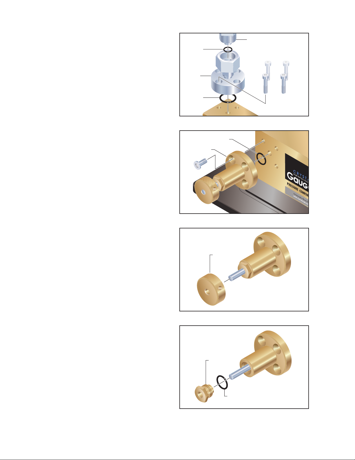
16 Use a 5mm Allen key to remove the four (4)
cap screws holding the rear Gauge Base to
the top of the Manifold Block. Then, lift the
Gauge Base and its o-ring (PN 3130) from
the Manifold Block and separate the Gauge
Adapter and its o-ring (PN 2018) from the
Gauge Base (gure 12). Remove the forward
Gauge Base by following the same procedure.
If the comparator is tted with an optional
Fine Adjust Kit, continue to step 18. If not,
you may skip ahead to step 24.
Note: A comparator without the Fine Adjust
option is instead tted with an Accessory
Cap, plus an o-ring that should be replaced.
The screws for the plate will require a 4mm
Allen key to remove. Screws included with
older Fine Adjust Kits will require a 5mm key,
while those included with recent, redesigned
kits will require a 4mm key.
18 Use either a 4- or 5mm Allen key to remove
the four (4) cap screws holding the Fine Ad-
just to the side of the Manifold Block, then
pull the Fine Adjust and its o-ring (PN 2018
or PN 3130) away from the Manifold Block
(gure 13).
19 Use a 3mm Allen key to loosen the set screw
inside the Fine Adjust knob, then slide the
knob o of the piston (gure 14).
20 Use a 15mm box wrench to remove the Fine
Adjust bushing from the body, then slide the
bushing and its o-ring (PN 2018) o of the
piston (gure 15).
21 With the front of the Fine Adjust body facing
toward you, turn the piston clockwise until
the piston threads are clear of the hole in the
back of the Fine Adjust body (gure 16).
22 From the back of the Fine Adjust body, slide
out the piston (gure 17).
Figure 12
Figure 13
Figure 14
Figure 15
Rear
Gauge
Base
Gauge
Adapter
O-ring
(PN 3130)
O-ring
(PN 2018)
O-ring
(PN 2018 or
PN 3130)
Fine Adjust
Fine Adjust
Knob
Fine Adjust
Bushing *
O-ring
(PN 2018)
*Whenreassembling, apply
Dow Corning 111 or a similar
silicone-based lubricant .

GaugeCalXP Service Instruction Sheet •Page 5
C R Y S T A L
engineering corporation
23 From the front of the Fine Adjust body,
remove the o-ring (PN 3129) and the backup
ring (PN 3150) (gure 18).
Note: The o-ring and backup ring may be
rmly seated in the Fine Adjust body. If so,
they can be extracted with a pair of tweezers
or other appropriate tool.
24 Use a 4mm Allen key to remove the four (4)
screws holding the Accessory Cap to the side
of the Manifold Block, then pull the cap and
its o-ring (PN 2018) away from the Manifold
Block (gure 19).
25 If the comparator is not tted with an
optional Fine Adjust, remove the second
Accessory Cap located on the other side of
the Manifold Block. Follow the procedure
outlined in step 24.
26 Clean all of the parts. Crystal recommends
you use an ultrasonic bath and an appropri-
ate cleaning solution.
In addition, we recommend that you use a
round brush to clean the piston hole in the
Manifold Block.
27 Reassemble the GaugeCalXP pressure com-
parator and optional Fine Adjust by follow-
ing the preceding steps in reverse order.
Replace all o-rings, backup rings, and main
seal with those supplied in the rebuild kit.
Refer to the illustrated parts list on page 6.
Dow Corning®111, or similar silicone-based
lubricants, are recommended for use on new
o-rings to ensure proper sealing.
When installing the gauge
bases, accessory caps, and ne
adjust; tighten the screws in the
order shown at right: rst to a
snug t, and then fully-torqued
to 85 in-lbs / 9.6 N-m.
List
Figure 16
Figure 17
Figure 18
Figure 19
1
32
4
Fine Adjust Piston
Fine Adjust Piston
Backup ring
(PN 3150)
O-ring
(PN 3129)
O-ring
(PN 2018)
Accessory
Cap
Page 6 •GaugeCalXP Service Instruction Sheet
C R Y S T A L
engineering corporation
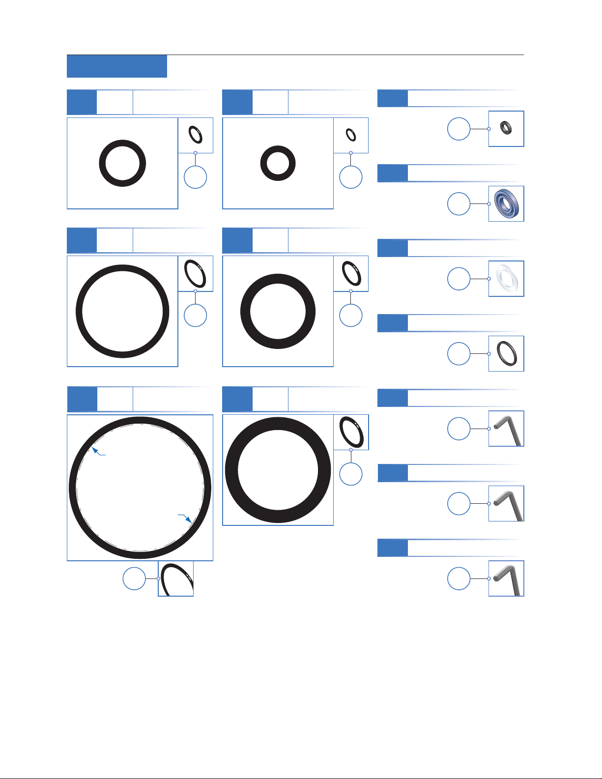
3143 Parts List
3130 O-ring 21.94mm x 1.78mm
0.864in x 0.070in
QTY
3
3150 Backup ring
3131 O-ring 1 5.1mm x 2.7mm
0.594in x 0.106in
QTY
1
3303
3376
O-ring See the dimensions
for each o-ringbelow.
O-ring 3303
34.65mm x 1.78mm
1.364in x 0.070in
QTY
1
3152 Rod Seal
QTY
1
3178 Allen key, 5mm
QTY
1
3177 Allen key, 4mm
QTY
1
3434 Rod Seal Backup
QTY
1
3176 Allen key, 3mm
QTY
1
QTY
1ea
O-ring 3376
35mm x 2.5mm
1.378in x 0.098in
2018 O-ring 9.25mm x 1.78mm
0.364in x 0.070in
QTY
6
3129 O-ring 6.07mm x 1.78mm
0.239in x 0.070in
QTY
1
3418 O-ring 21.82mm x 3.53mm
0.859in x 0.139in
QTY
1
3151 Backup ring
QTY
1
Notes:
The full-size o-ring diagrams may not
reproduce to scale when printed from
the pdf download.
All o-ring dimensions provide rst the
inside diameter, then the thickness.

GaugeCalXP Service Instruction Sheet •Page 7
C R Y S T A L
engineering corporation
How to Contact Us:
Phone (805) 595-5477
Toll-Free (800) 444-1850
Fax (805) 595-5466
Email service@crystalengineering.net
Web www.crystalengineering.net
Send your comments to: feedback@crystalengineering.net
Routine Flushing
If a complete rebuild is not required, ushing the GaugeCalXP can serve as a quick and simple way
to remove small amounts of dirt or sediment from the system. Flushing can also be used to ensure
that any air is removed from the system prior to performing a calibration test. Flushing the unit
should never serve as a substitute for a rebuild; and remember that any service beyond a routine
ush should always be performed by a qualied technician.
Flushing Instructions
1Remove all gauges from the GaugeCalXP pressure comparator.
2To completely open the reservoir, wind the handle counter-clockwise until you feel it stop.
3Securely grip the front of the Baseplate (near the bearing block) and lift to tip the GaugeCalXP
on its end. Any hydraulic uid in the system will run out through the rear Gauge Base port.
4Set the unit back down, at on the Baseplate, and begin to pour isopropyl alcohol, warm soapy
water, or clean hydraulic oil into the reservoir. Continue to ll the unit until the uid begins to
run out of the Gauge Base ports. Always dispose of uids in a responsible manner.
5Once again, tip the GaugeCalXP on its end until all of the uid in the system has drained out.
6Set the unit back down, then wind the handle clockwise at least 10 turns, then ll the reservoir
with test uid to within 6mm (1/4") from the top.
7Follow the operator instructions supplied with your GaugeCalXP to ll the system and begin
calibration testing.
CAUTION: Solvents can damage o-rings and should never be used when ushing or otherwise
cleaning the GaugeCalXP.

CRYSTAL
engineering corporation
© 2006 Crystal Engineering Corporation
708 Fiero Lane, Suite 9, San Luis Obispo, California 93401-8701
PN: 3175—Rev D
Table of contents
Other Crystal Test Equipment manuals

Popular Test Equipment manuals by other brands


Martindale Electric
Martindale Electric PD440S instruction manual

MULTI MEASURING INSTRUMENTS
MULTI MEASURING INSTRUMENTS ALCL-40 instruction manual

Atel Electronics
Atel Electronics DADI DA280 user guide

VOLTCRAFT
VOLTCRAFT VC-BT100 operating instructions

Klein Tools
Klein Tools NCVT-2P instructions

Varytec
Varytec Blitz Bar 240 user manual


