CS Instruments VD 500 User manual

VD 500 English V1.07 Seite 1 von 40
Instruction manual
Flow sensor VD 500
with Display, 4 ... 20 mA and Pulse output (galv. isolated)
Stationary and mobile
flow and consumption measurement for compressed air and gases
www.cs-instruments.com
EN - English
Sales Office South
Zindelsteiner Straße 15
D-78052 VS-Tannheim
DEUTSCHLAND
Tel.: +49 (0) 7705 978 99-0
Fax: +49 (0) 7705 978 99-20
Sales Office North
Gewerbehof 14
D-24955 Harrislee
Deutschland
Tel.: +49 (0) 461 700 20 25
Fax: +49 (0) 461 700 20 26

Table of Content
VD 500 English V1.07 Seite 2 von 40
II. Table of content
II. Table of content......................................................................................................... 2
1Intended use.................................................................................................................. 4
2Safety instructions........................................................................................................ 4
3Instruments description ............................................................................................... 5
4Technical data............................................................................................................... 6
5Installation..................................................................................................................... 7
5.1 Pipe/tube requirements ......................................................................................................... 7
5.2 Inlet / outlet runs .................................................................................................................... 7
5.3 Installation VD 500................................................................................................................. 8
5.3.1 ½“ welded nipple with ball valve ½“ ................................................................................... 8
5.3.2 Spot drilling collar with ball valve....................................................................................... 8
5.4 Installation of the Sensor...................................................................................................... 9
5.4.1 Mounting VD 500 onto the ball valve................................................................................. 9
5.4.2 Installation angle for locations that potentially hold water ............................................... 10
5.5 Display Head Position ......................................................................................................... 10
6Commissioning............................................................................................................11
6.1 Zero Point Adjustment......................................................................................................... 11
6.2 4… 20 mA Analogausgang.................................................................................................. 11
7Measuring ranges........................................................................................................12
7.1 Maximum Flow ranges „High speed“ ................................................................................ 13
7.2 Maximum Flow ranges „Ultra speed“ ................................................................................ 14
8Dimension ....................................................................................................................15
9Electrical wiring ...........................................................................................................16
9.1 Modbus RTU, 4..20mA, Pulse or MBus.............................................................................. 16
9.2 Ethernet (optional PoE) ...................................................................................................... 17

Table of Content
VD 500 English V1.07
Seite 3 von 40
10 Operation...................................................................................................................18
10.1 Initialization .......................................................................................................................... 19
10.2 Main menu ............................................................................................................................ 19
10.3 Settings................................................................................................................................. 20
10.3.1 Sensor Setup................................................................................................................... 21
10.3.1.1 Input / change tube diameter.................................................................................... 21
10.3.1.2 Input / change consumption counter ........................................................................ 22
10.3.1.3 Definition of the units for flow, velocity, temperature and pressure ......................... 22
10.3.1.4 Definition of the reference conditions....................................................................... 23
10.3.1.5 Setting of Zeropoint and Low-flow cut off................................................................. 25
10.3.2 Modbus Settings.............................................................................................................. 26
10.3.2.1 Modbus RTU Setup.................................................................................................. 26
10.3.2.2 Modbus TCP (Optional)............................................................................................ 27
10.3.2.2.1 Network Setup DHCP........................................................................................... 27
10.3.2.2.2 Network Settings static IP..................................................................................... 28
10.3.2.2.3 Modbus TCP Settings........................................................................................... 29
10.3.2.3 Modbus Settings Register (2001…2005) ................................................................ 30
10.3.2.4 Values Register (1001 …1500) ................................................................................ 30
10.3.3 Pulse /Alarm..................................................................................................................... 32
10.3.3.1 Pulse output.............................................................................................................. 32
10.3.4 User Setup....................................................................................................................... 33
10.3.4.1 Password.................................................................................................................. 33
10.3.4.2 Language.................................................................................................................. 33
10.3.4.3 Display / Touch......................................................................................................... 34
10.3.5 Advanced......................................................................................................................... 34
10.3.6 4 -20mA ........................................................................................................................... 35
10.3.7 VD 500 Info...................................................................................................................... 37
10.4 MBus...................................................................................................................................... 37
10.4.1 Default Settings communication...................................................................................... 37
10.4.2 Default values transmitted ............................................................................................... 37
11 Status / Error messages...........................................................................................38
11.1 Status messages.................................................................................................................. 38
11.2 Error messages.................................................................................................................... 39
12 Maintenance..............................................................................................................40
13 Re-Calibration...........................................................................................................40
14 Spare parts and repair..............................................................................................40
15 Calibration.................................................................................................................40
16 Warranty....................................................................................................................40
Safety Instructions
VD 500 English V1.07 Seite 4 von 40
1 Intended use
The VD 500consumption sensor is used for continuous flow measurements, based on a dynamic
pressure / differential pressure measurement.
The VD 500 consumption sensor is designed and constructed exclusively for the intended purpose
described here and may only be used accordingly.
The user must check whether the instrument is suitable for the selected application. It must be
ensured that the medium is compatible with the wetted parts. The technical data listed in the data
sheet are binding.
Improper handling or operation outside the technical specifications is not permitted. Claims of any kind
based on improper use are excluded.
2 Safety instructions
Please read carefully before starting the device!
Warning:
Do not exceed the pressure range of 16 bar.
Over 10 bar we recommend using the high-pressure protection for a safe installation and removal.
Observe the measuring ranges of the sensor!
Overheating destroys the sensor.
Observe the admissible storage and transportation temperature as well as the permitted operating
temperature (e.g. protect the instrument from direct insolation).
Always observe the direction of flow when positioning the sensor!
The safety ring at the sensor head must always remain undamaged and sit correctly in the destined
slot.
The screwed fixture must be pressure tight.
The adapter sleeve must be tightened with a torque of 20 to 30 Nm.
It is necessary to avoid condensation on the sensor element or water drops in the measuring air as
they may cause faulty.
The values of the inlet and outlet sections must not fall below the specified minimum values as this
causes increased deviations in the measuring results.
The manufacturer cannot be held liable for any damage that occurs because of non-observance or
non-compliance with these instructions. Should the device be tampered with in any matter other than a
procedure, which is described and specified in the manual, the warranty is cancelled and the
manufacturer is exempt from liability.
The device is destined exclusively for the described application.
CS Instruments GmbH offers no guarantee for the suitability for any other purpose and is not liable for
errors that may have slipped into this operation manual. CS Instruments GmbH is also not liable for
consequential damage resulting from the delivery, capability or use of this device.
We offer you to take back the instruments of the instruments family VD 500 which you would like to
dispose of.
Qualified employees from the measurement and control technology branch should only carry out
adjustments and calibrations.
!

Instruments description
VD 500 English V1.07 Seite 5 von 40
3Instruments description
The VD 500 is a compact consumption counter for compressed air and gases.
Special features:
- Optimum accuracy due to compact design
- Intgrated Display showing Flow, consuption, velocity and temperature
- Input inner tube diameter via display keys
- Units free selectable. m³/h, m³/min, l/min, l/s, kg/h, kg/min, kg/s, cfm
- Modbus RTU (RS485) Interface
- Analogoutput 4..20mA
- Pulse output galv. isolated.
CS Instruments Service Software
- Analogaoutput 4...20 mA scaleabler
- Selection of gas type (Air, Nitrogen, Argon, Nitrous oxide, CO2, Oxygen, Natural gas)
- Read out Service data
- Sensordiagnose

Technical data
VD 500 English V1.07 Seite 6 von 40
4Technical data
Measurement: Flow, Consumption, Velocity and Pressure
Reference: Standard settings ex works:
DIN 1945, ISO 1217 at 20°C and 1000 mbar
other standards can be adjusted by Display keys (optional)
or means of the CS Service Software.
Selectable Units: m³/h (Standard settings ex- factory)
m³/min, l/min, l/s, ft/min, cfm, m/s, kg/h, kg/min, kg/s, °C, °F
Measuring principle: Differential pressure
Sensor: Pressure, NTC
Measuring medium: Air, gases
Operating temperature: -20 ... 70°C housing
Medium temperature: -30 ... 180°C probe tube
Relative humidity for
measuring medium: < 95 % r.H (no condensation on the sensor element allowed)
Operating pressure: up to 20 bar
Power supply: 18 to 36 VDC
Power consumption: max. 5W
Digital output: RS 485 (Modbus RTU)
Optional: MBus, Ethernet (PoE)
Analog output: 4...20 mA (see tables page 13 -18),
max. burden < 500 Ohm
Pulse output: pulse output potential free (dry contact)
passive: max. 48Vdc, 150mA
1 pulse pro m³ resp. pro l,
Valency adjustable with the display keys
Accuracy: ± 1,5 % m.v.*, ± 0,3 % f.s. (20..224m/s)*
± 1,5 % m.v (>224 m/s)
Display: optional TFT 1.8“ Resolution 220 x 176
Mounting thread: G ½“, optional ½” NPT
Material: Stainless steel 1.4301 / 1.4404
Protection class IP65
‘* m.v. = measured values
f.s. = full scale
Installation
VD 500 English V1.07 Seite 7 von 40
5 Installation
5.1 Pipe/tube requirements
•Correctly sized gaskets
•Correct aligned flanges and gaskets
•Diameter mismatch at the pipe junctions should be avoided but must be less than 1mm. For
further information see ISO 14511
•Ensure clean pipes after installation
•.
5.2 Inlet / outlet runs
In order to maintain the accuracy stipulated in the data sheets, the sensor must be inserted in the centre
of a straight pip e section with an undisturbed flow progression.
An undisturbed flow progression is achieved if the sections in front of the sensor (inlet) and behind the
sensor (outlet) are sufficiently long, straight and without any obstructions such as edges, seams, curves
etc.
Therefore, it is necessary to ensure the recommended inlet and outlet runs.
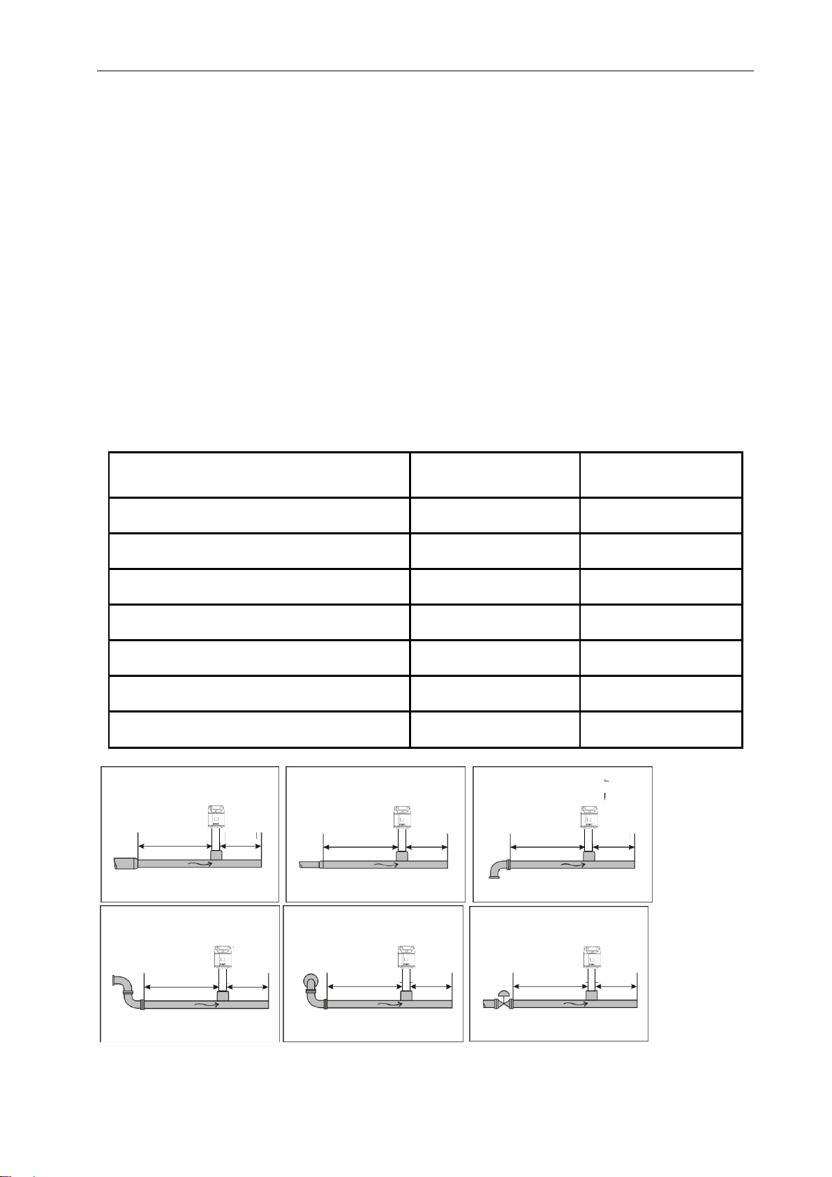
Table Inlet / Outlet runs
Flow obstruction before the measurement
section
Min length
Inlet run (L1)
Min length
Outlet run (L2)
Slight curve
(elbow < 90°)
12 x D
5 x D
Reduction
(Pipe narrows to the measurement section)
15 x D
5 x D
Expansion
(Pipe expands to the measurement section)
15 x D
5 x D
90° elbow or T-piece
15 x D
5 x D
2x elbow á 90°
in einer Ebene
20 x D
5 x D
2x elbow á 90°
3-dimensional
35 x D
5 x D
Control valve
45 x D
5 x D
15 x D 5 x D
15 x D 5 x D15 x D
15 x D 5 x D
20 x D 5 x D
35 x D 5 x D
5 x D45 x D
The values represent the min. lengths. In case the min. inlet / outlet runs could not be ensured, it must be
expected to get increased or significant deviations of the measurement values.
Installation
VD 500 English V1.07
Seite 8 von 40
5.3 Installation VD 500
The installation of the sensor is done via a ball valve ½ ".
If no valid measuring point with a ball valve ½ " is available there are following ways to set up a
measuring point.
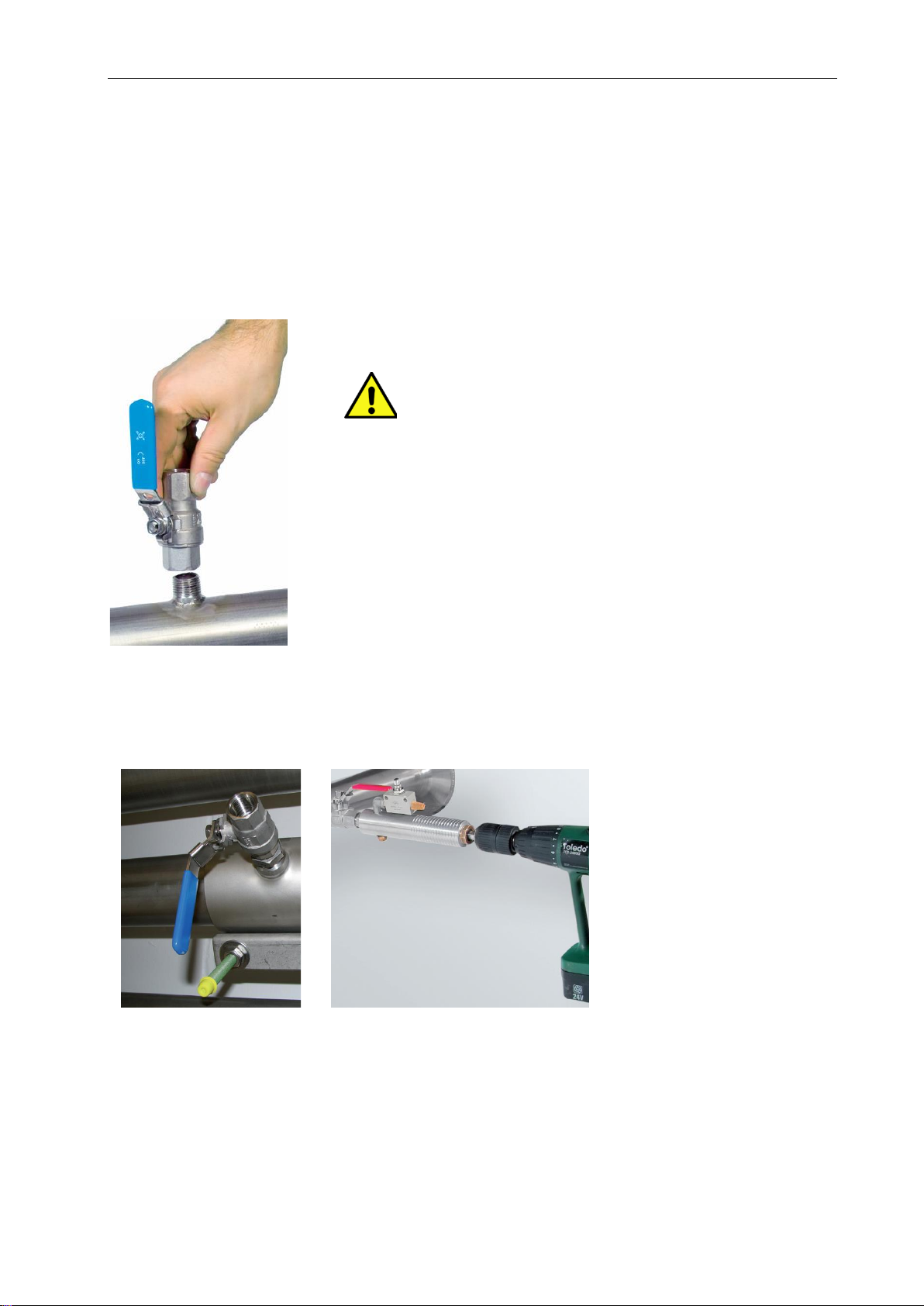
5.3.1 ½“ welded nipple with ball valve ½“
5.3.2 Spot drilling collar with ball valve
In case the system could not be shut down, means to be set depressurized, there could be used the CS
spot drilling collar (Order-No. 0530 1108) and drilling jig (Order-No. 0530 1108) to drill through the ball
valve.
Important:
Ensure that the system is in shut down, ie. depressurized.
Note for installation with ball valve
Ball valve R 1/2“, DN 15
Passage ball valve: Minimum Ø15 mm

Installation
VD 500 English V1.07
Seite 9 von 40
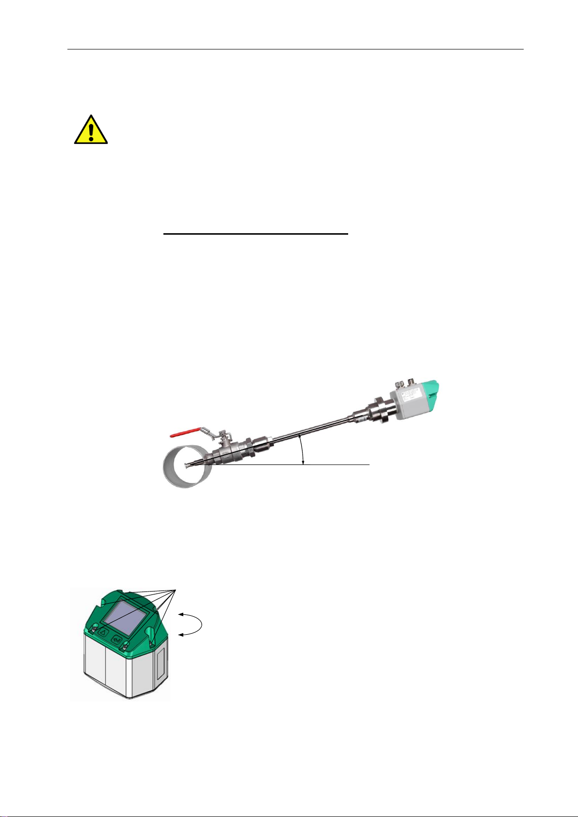
5.4 Installation of the Sensor
5.4.1 Mounting VD 500 onto the ball valve
•Assembly is carried out by inserting the connection thread with gasket. (G1/2“
thread, SW 32) into the ball valve with ½"internal thread.
The sensor has be tighten by hand as far as possible and then tighten with
stipulated torque of 25-30 Nm.
It must be ensured that the installation is pressure-tight.
•The sensor is then inserted to the required immersion depth (sensor tip in the
middle of pipe) and aligned according to the direction of the airflow.
A depth scale engraved on the probe tube, a flow alignment arrow and an
aligning device will be of help for you.
Once the sensor has been aligned the adapter sleeve must be tighten with
stipulated torque of 20-30Nm (SW 17).
Attention: Alignment of the sensor must not be modified when tightening the connection thread and
adapter sleeve. In this case, please check the immersion depth and alignment again and
correct it if necessary. The angular deviation should not be greater than 2° in relation to
ideal position as otherwise the measuring accuracy will decrease.
Calculation mounting depth: Alignment flow direction
Mounting depth = X + Y
dA = outer diameter
X = dA / 2
y
dA
x
160
170
180
Installation depth
Engraved depth scale for
accurate installation
Safety ring
Adapter sleeve
Connection thread
Sensor alignment
A max. angle deviation of ±2° is permitted to ensure correct
measured values..
Indication flow direction
Installation
VD 500 English V1.07
Seite 10 von 40
5.4.2 Installation angle for locations that potentially hold water
Location that potentially hold water should be avoided !
•It is recommended to install the VD 500 at an angle of 15 degrees (see
picture).This allows condensate or water to drip off in the event that it is
present.
•Installations in risers are basically possible.
•Not permitted installation of the VD 500:
oupside down sensor installation as condensate / water may no longer
drain off.
oAn installation from above (vertical) is also not permitted as water
penetration leads to measurement errors.
oAn installation in downpipes
15,0 °
5.5 Display Head Position
The Position of the Display head is twistable by 180 e.g. in
case of reverse flow direction.
For this purpose the 6 fastening screws are to be released
and the display head rotated 180°.
Caution:
It must be ensured that the connection plugs are still plugged
and the gasket is installed correctly.
Fastening screws

Commissioning
VD 500 English V1.07 Seite 11 von 40
6 Commissioning
The consumption sensor VD 500 measures the flow velocity (differential pressure principle) in the
center of the pipe.
6.1 Zero Point Adjustment
In order to achieve the required measurement accuracy, a zero point adjustment of
the sensor must first be carried out at the start of the measurement.
•To do this, pull the sensor out completely to the stop.
•Then start the zero point calibration on the sensor.
Main menu →Sensor settings→Zero point, see also chapter 10.3.1.5
Carrying out the zero point adjustment again is recommended every 180 days!
6.2 4… 20 mA Analogausgang
➢VD 500 with Display with 4… 20 mA analogue- and pulse output
Please enter inner diameter of the pipe!
Values indicated in the display:
Actual value in m³/h, m³/min etc.
Counter in m³, l, cf
as well as pulse output, 1 pulse per m³, l, cf
are calculated according to the set diameter. Please take the analogue value for flow rate
4. 20 mA from the tables on pages 13 - 14
4 mA always corresponds with the starting value 0 m³/h, 0 m³/min. The final value 20 mA can be taken
from the tables on pages 13 -17.
Example VD 500 High Speed version:
1“ with inner diameter 25,0 mm: 4mA = 0 m³/h 20 mA = 295 m³/h
2“ with inner diameter 53,1 mm: 4mA = 0 m³/h 20 mA = 1450 m³/h
➢VD 500 without Display with 4… 20 mA analogue- and pulse output
No adjustments are necessary at the consumption sensor.
The respective final values for the flow rate can be taken from the tables on the pages xx - xx.
Analogue start value 4 mA is always set as scaling value 0 m³/h, 0 m³/min etc.
Analogue end value 20 mA is the final value, see tables pages 13 –17..
Example VD 500 High Speed -Version:
1“ with inner diameter 25,0 mm: 4mA = 0 m³/h 20 mA = 295 m³/h
2“ with inner diameter 53,1 mm: 4mA = 0 m³/h 20 mA = 1450 m³/h

Measuring ranges
VD 500 English V1.07 Seite 12 von 40
7Measuring ranges
The consumption sensor VD 500 is available in 2 different versions:
•High Speed–Version max. measuring range of 224.0 m/s
•Ultra Speed –Version max. measuring range of 600.0 m/s
The sensors are programmed to pipe inner diameter of 53,1 mm.
Measuring range Analogoue output Scaling
•High Speed –Version 0 ...1450 m³/h 4mA =0 m³/h, 20mA = 1450 m³/h
•Ultra Speed –Version 0 ...2114 m³/h 4mA =0 m³/h, 20mA = 2114 m³/h
In case of use in other inner pipe diameter the diameter, using the display version, the diameter has to be
set first.
The corresponding scale values for the respective version could be found in sections 5.1 to 5.3.
Example:
Pipe 1“, Inner diameter 25mm Measuring range Analogoue output Scaling
•High Speed –Version 0 ...295 m³/h 4mA =0 m³/h, 20mA = 295 m³/h
•Ultra Speed–Version 0 ...430 m³/h 4mA =0 m³/h, 20mA = 430 m³/h
For changing the inner pipe diameter and adjusting the 4…20mA scaling, please refer to chapter
“Operation”.
Please note:
The area outside the pipe (environment of the sensor) is not allowed to be an explosive area. (Ex area) .

Measuring ranges
VD 500 English V1.07
Seite 13 von 40
The end values refer to application-typical conditions of 7 bara + 50°C.
The end values of the consumption sensor VD 500 depend on temperature and pressure and change
with changing operating conditions..
7.1 Maximum Flow ranges „High speed“
Inner diameter
of the pipe
Flow
(final value of
measuring range in
Nm³/h)
Max
Inner diameter
of the pipe
Flow
(final value of measuring
range in Nm³/h)
Max.
Inchl
mm
Air2)
Air 3)
m/s
Inch
mm
Air2)
Air 3)
m/s
3/4"
21,7
215
198
224,0
3"
80,0
3364
3097
224,0
1"
25,0
295
272
224,0
82,5
3582
3297
224,0
26,0
321
296
224,0
84,9
3794
3492
224,0
27,3
357
328
224,0
90,0
4268
3929
224,0
28,5
391
360
224,0
4"
100,0
5276
4856
224,0
30,0
437
402
224,0
107,1
6059
5577
224,0
1 1/4"
32,8
529
487
224,0
110,0
6391
5883
224,0
36,0
644
592
224,0
5"
125,0
8263
7606
224,0
36,3
655
603
224,0
133,7
9453
8701
224,0
1 1/2"
39,3
775
713
224,0
6"
150,0
11913
10965
224,0
40,0
804
740
224,0
159,3
13436
12367
224,0
41,9
886
816
224,0
182,5
17656
16251
224,0
43,1
941
866
224,0
190,0
19137
17614
224,0
45,8
1068
983
224,0
8"
200,0
21230
19540
224,0
2"
50,0
1283
1180
224,0
206,5
22632
20831
224,0
51,2
1346
1239
224,0
10"
250,0
33211
30568
224,0
53,1
1450
1335
224,0
260,4
36075
33204
224,0
54,5
1529
1408
224,0
12"
300,0
47881
44070
224,0
57,5
1713
1577
224,0
309,7
51027
46966
224,0
60,0
1870
1721
224,0
339,6
61356
56473
224,0
64,2
2148
1977
224,0
400,0
85122
78347
224,0
2 1/2"
65,0
2205
2029
224,0
500,0
133003
122417
224,0
70,3
2589
2383
224,0
600,0
191524
176281
224,0
71,1
2648
2437
224,0
700,0
260685
239938
224,0
76,1
3041
2799
224,0
800,0
340487
313388
224,0
900,0
430929
396632
224,0
1000,0
532011
489669
224,0
2) Referred to DIN 1945 / ISO 1217 (20°C, 1000mbar) and compressed air.
3) Referred to DIN 1343: 0°C, 1013,25 mbar

Measuring ranges
VD 500 English V1.07
Seite 14 von 40
7.2 Maximum Flow ranges „Ultra speed“
Inner diameter
of the pipe
Flow
(final value of
measuring range in
Nm³/h)
Max
Inner diameter
of the pipe
Flow
(final value of
measuring range in
Nm³/h)
Max
Inchl
mm
Air2)
Air 3)
m/s
Inchl
mm
Air2)
Air 3)
m/s
3/4"
21,7
578
531
600,0
3"
80,0
9012
8286
600,0
1"
25,0
791
727
600,0
82,5
9595
8822
600,0
26,0
860
791
600,0
84,9
10162
9344
600,0
27,3
956
879
600,0
90,0
11433
10512
600,0
28,5
1048
964
600,0
4"
100,0
14132
12994
600,0
30,0
1171
1077
600,0
107,1
16229
14922
600,0
1 1/4"
32,8
1416
1302
600,0
110,0
17120
15741
600,0
36,0
1724
1585
600,0
5"
125,0
22134
20351
600,0
36,3
1755
1614
600,0
133,7
25321
23282
600,0
1 1/2"
39,3
2075
1908
600,0
6"
150,0
31910
29340
600,0
40,0
2152
1979
600,0
159,3
35990
33091
600,0
41,9
2374
2183
600,0
182,5
47293
43484
600,0
43,1
2521
2318
600,0
190,0
51260
47131
600,0
45,8
2861
2631
600,0
8"
200,0
56865
52285
600,0
2"
50,0
3435
3158
600,0
206,5
60621
55738
600,0
51,2
3607
3316
600,0
10"
250,0
88958
81793
600,0
53,1
3884
3571
600,0
260,4
96628
88845
600,0
54,5
4097
3767
600,0
12"
300,0
128252
117922
600,0
57,5
4588
4218
600,0
309,7
136680
125690
600,0
60,0
5008
4605
600,0
339,6
164345
115130
600,0
64,2
5755
5291
600,0
400,0
228004
209670
600,0
2 1/2"
65,0
5906
5430
600,0
500,0
356256
327610
600,0
70,3
6934
6376
600,0
600,0
513009
471758
600,0
71,1
7092
6521
600,0
700,0
698262
642116
600,0
76,1
8145
7489
600,0
800,0
912017
838682
600,0
900,0
1154271
1061458
600,0
1000,0
1425026
1310441
600,0
2) Referred to DIN 1945 / ISO 1217 (20°C, 1000mbar) and compressed air.
3) Referred to DIN 1343: 0°C, 1013,25 mbar
Dimensions
VD 500 English V1.07 Seite 15 von 40
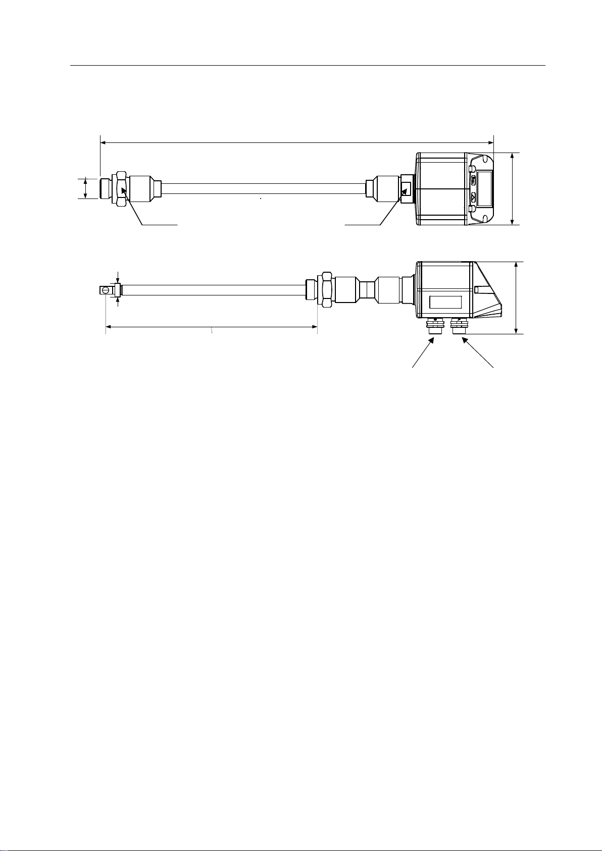
8Dimension
416,0 (Standard Schaft 220mm)
76,5
G ½“
(ISO 228/1)
SW 32 SW 27
75,0
220 mm(Standard)
Optional: 120, 160, 300, 400 mm
Ø11,7
Connector plug A
Connector plug B
Electrical wiring
VD 500 English V1.07
Seite 16 von 40
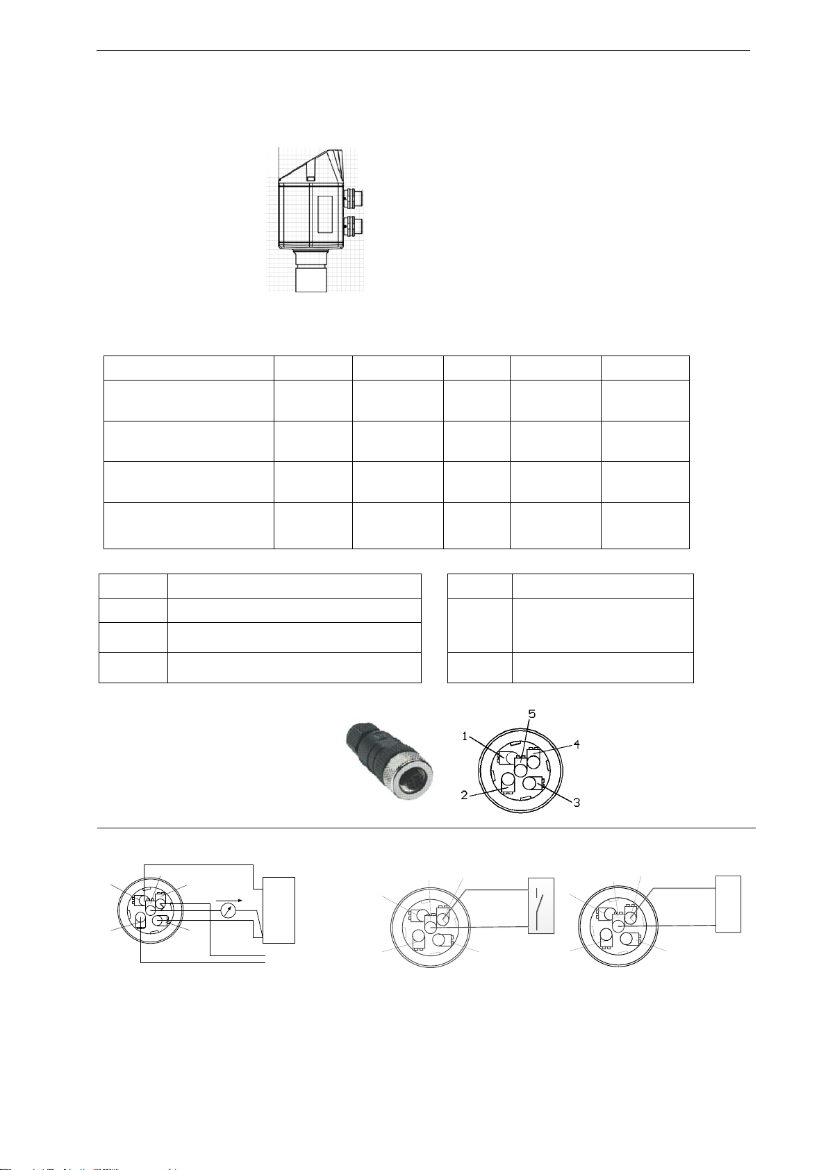
9Electrical wiring
9.1 Modbus RTU, 4..20mA, Pulse or MBus
Attention: Not required connections NC must not be connected to a voltage and/or to
protection earth. Cut and insulate cables.
Pin 1
Pin 2
Pin 3
Pin 4
Pin 5
Connector plug A
+VB
RS 485 (A)
-VB
RS 485 (B)
I+
4..20 mA
Connector plug B
Pulse output (standard)
NC
GND
DIR
Pulse
galv. isolated
Pulse
gavl. isolated
Connector plug B
Option MBus
NC
GND
DIR
MBus
MBus
Colours pulse cables
0553 0106 (5 m)
0553.0107 (10 m)
brown
white
blue
black
grey
Legend:
-VB
Negative supply voltage 0 V
Pulse
Pulse for consumption
+VB
Positive supply voltage 18...36 VDC smoothed
NC
Must not be connected to a voltage
and/or to protection earth. Please
cut and isolate cables.
I +
Current signal 4...20 mA –selected measured
signal
RS 485 (A)
RS 485 (B)
Modbus RTU A
Modbus RTU A
MBus
MBus (reverse polarity protected)
If no connection cable/ pulse
cable is ordered the sensor will
be supplied with a M12
connector plug. The user can
connect the supply and signal
cables as indicated in the
connection diagram.
.
M12 Connector plug
View from back side
(terminal side)
Connector plug A (M12 - A-coding) Connector plug B (M12 - A-coding)
3
4
5
1
2
+ VB
- VB
4 … 20mA
+ -
Grau / Grey
Blau / Blue
Weiss / White
Schwarz / Black
Modbus (B)
Modbus (A)
Braun / Brown
Remark: If the sensor is placed at the end of the Modbus system a termination is required. The sensors have
an internal switchable termination, therefore the 6 fastening screws from the lid are to be released
and set the internal DIP Switch to “On”. It must be ensured that the connection plugs are still plugged
and the gasket is installed correctly.
Alternatively, a 120R resistor can be installed in the plug between pin 2 and pin 4.
3
4
5
1
2
Grau / Grey
Schwarz / Black
Impulsausgang / Pulse output
3
4
5
1
2
Grau / Grey
Schwarz / Black
MBus
Option MBus
Connector plug A
Connector plug B
Electrical wiring
VD 500 English V1.07
Seite 17 von 40
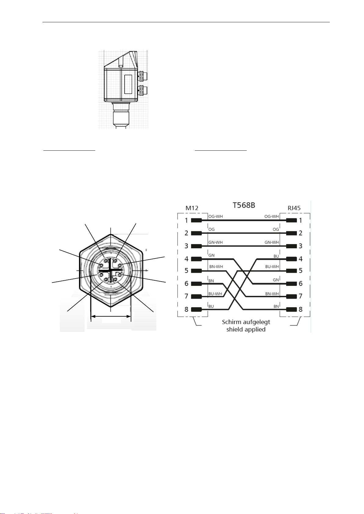
9.2 Ethernet (optional PoE)
Connector plug B Connection cable
M12 x-coded 8 pole M12 x-coded to RJ45
Data LINES: 1,2 und 3,4
PoE LINES: 5,6 und 7,8
2
81
3
5 4
6
7
M12 x 1
Connection cable: Cat 6.
*PoE: Power over Ethernet
- Connector plug B (M12 X-coded 8 pole)
- Connector plug A
Operation
VD 500 English V1.07 Seite 18 von 40
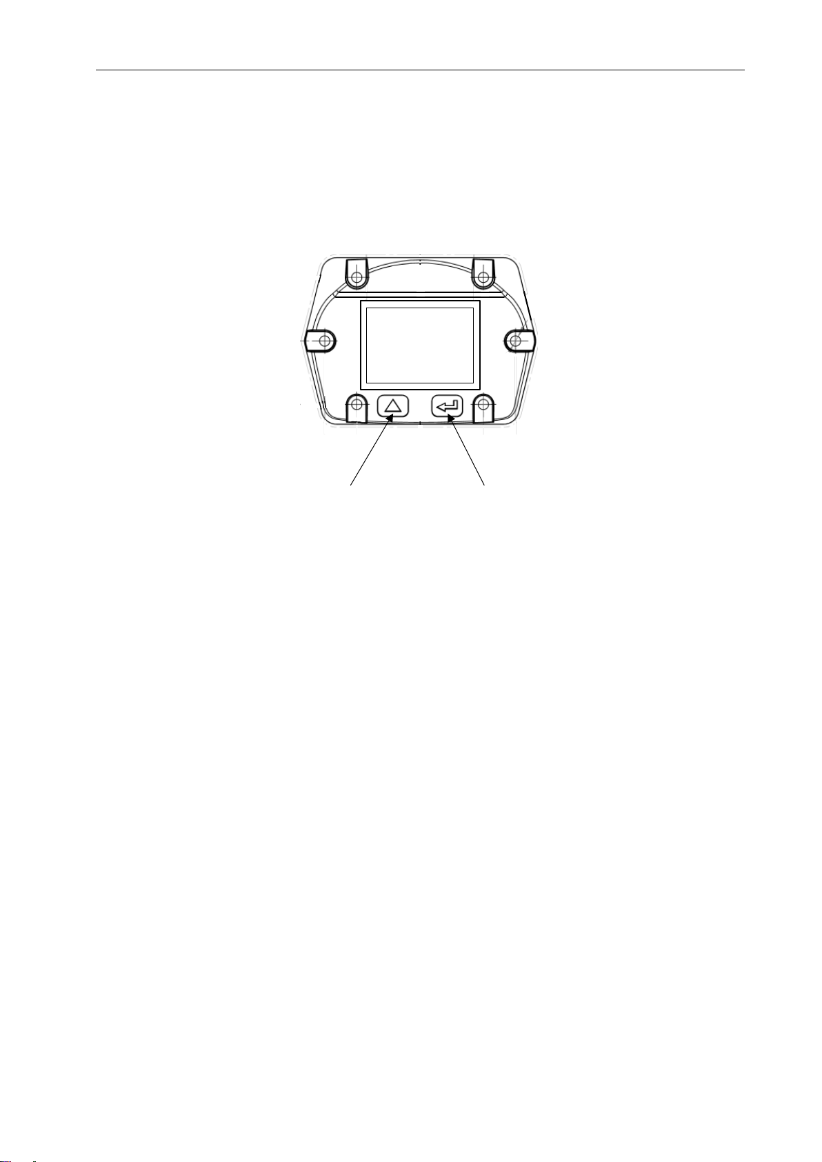
10 Operation
Remark: In version with display only.
“Up“ ( ) “OK“ ( )
The operation of the VD 500 is done by the two capacitive key buttons Up () und Enter ()
Operation
VD 500 English V1.07
Seite 19 von 40
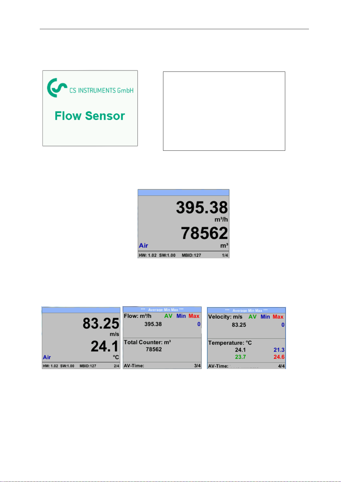
10.1 Initialization
10.2 Main menu
HW Version Page-No.
Gas /
Status Info
SW Version Modbus ID
*** VA 500 ***
Switching to pages 2-4 or back by pressing key „“
*** VA 500 ***
391.23
391
1 minutes
410,34
1 minute
91,3282.46
AV-Time ( Period for average value calculation) could be changed under Sensor Setup.-Advanced–AV-
Time
After switching on the VD 500, the initialized
screen is displayed followed by the main
menu.
*** VD 500 ***

Operation
VD 500 English V1.07
Seite 20 von 40
10.3 Settings
The settings menu could accessed by pressing the key „OK“.
But the access to the settings menu is password protected.
Selection of a menu item or to change a value
is done with the key „“,a final move to the
chosen menu item or takeover of the value
change needs the confirmation by pressing the
key „OK“
Factory settings for password at the time of
delivery: 0000 (4 times zero).
If required the password could be changed at
Setup–User setup-Password.
.
Table of contents
Other CS Instruments Accessories manuals

CS Instruments
CS Instruments VA 500 User manual

CS Instruments
CS Instruments FA 550 User manual

CS Instruments
CS Instruments Vortex VX 570 User manual

CS Instruments
CS Instruments VA 550 User manual

CS Instruments
CS Instruments VA 452 User manual

CS Instruments
CS Instruments VA 400 User manual

CS Instruments
CS Instruments VA 570 User manual

CS Instruments
CS Instruments VA 525 User manual

CS Instruments
CS Instruments VA 500 User manual

CS Instruments
CS Instruments VA 521 User manual


