CS Instruments VA 570 User manual

VA 570 English V1.19 Page 1 of 44
EN - English
Instruction manual
Flow Sensor
VA 570

Foreword
VA 570 English V1.19 Page 2 of 44
I. Foreword
Dear customer,
thank you very much for deciding in favour of the VA 570. Please read this installation and
operation manual carefully before mounting and initiating the device and follow our advice.
A riskless operation and a correct functioning of the VA 570 are only guaranteed in case of
careful observation of the described instructions and notes
Sales Office South / Geschäftsstelle Süd
Zindelsteiner Str. 15
D-78052 VS-Tannheim
Tel.: +49 (0) 7705 978 99 0
Fax: +49 (0) 7705 978 99 20
Mail: info@cs-instruments.com
Web: http://www.cs-instruments.com
Sales Office North / Geschäftsstelle Nord
Am Oxer 28c
D-24955 Harrislee
Tel.: +49 (0) 461 700 20 25
Fax: +49 (0) 461 700 20 26
Web: http://www.cs-instruments.com

Table of Content
VA 570 English V1.19 Page 3 of 44
II. Table of Content
I. Foreword ....................................................................................................................... 2
II. Table of Content ........................................................................................................ 3
1Pictograms and Symbols ............................................................................................. 5
2Signalwords according ISO 3864 and ANSI Z 535...................................................... 5
3Safety instructions........................................................................................................ 6
3.1 Intended Use........................................................................................................................... 7
3.2 Installation and commissioning ........................................................................................... 7
4Technical data............................................................................................................... 8
4.1 Signal circuits......................................................................................................................... 9
4.1.1 Modbus.............................................................................................................................. 9
4.1.2 Current output.................................................................................................................... 9
4.1.2.1 Aktive.......................................................................................................................... 9
4.1.2.2 Passive....................................................................................................................... 9
4.1.3 Pulse.................................................................................................................................. 9
4.1.4 Alarm.................................................................................................................................. 9
4.2 Measuring range flow VA 570............................................................................................. 10
5Dimensions ..................................................................................................................11
5.1 Dimension VA 570 Thread-version..................................................................................... 11
5.2 Dimension VA 570 Flanged-version................................................................................... 12
6Installation....................................................................................................................13
6.1 Pipe/tube requirements ....................................................................................................... 13
6.2 Inlet / outlet runs .................................................................................................................. 13
6.2.1 Installation of VA 570...................................................................................................... 14
6.3 Alignment Display (Housing).............................................................................................. 14
6.4 Tightening torques............................................................................................................... 15
7Connection diagram ....................................................................................................16
7.1 Cable glands - clamping ranges......................................................................................... 16
7.2 Connector pin assignment.................................................................................................. 16
7.3 Wire connection ................................................................................................................... 18
7.3.1 General:........................................................................................................................... 18
7.3.2 Power supply ................................................................................................................... 18
7.3.3 Modbus RTU................................................................................................................... 18
7.3.4 Modbus TCP (Ethernet) Optional PoE ............................................................................ 19
7.3.5 Pulse Output.................................................................................................................... 19

Table of Content
VA 570 English V1.19 Page 4 of 44
8Operation VA 570.........................................................................................................20
8.1 Main menu (Home)............................................................................................................... 21
8.1.1 Intialization....................................................................................................................... 21
8.2 Main menu ............................................................................................................................ 21
8.3 Settings................................................................................................................................. 22
8.3.1 Sensor Setup................................................................................................................... 22
8.3.1.1 Input / change tube diameter.................................................................................... 22
8.3.1.2 Input / change consumption counter........................................................................ 23
8.3.1.3 Definition of the units for flow, velocity, temperature and pressure ......................... 23
8.3.1.4 Definition of the reference conditions....................................................................... 24
8.3.1.5 Setting of Zeropoint and Low-flow cut off................................................................. 26
8.3.2 Modbus RTU.................................................................................................................... 27
8.3.2.1 Setup ........................................................................................................................ 27
8.3.3 Modbus TCP (Optional)................................................................................................... 28
8.3.3.1 Setup ........................................................................................................................ 28
8.3.3.1.1 Network Setup DHCP........................................................................................... 28
8.3.3.1.2 Network Settings static IP..................................................................................... 29
8.3.3.1.1 Modbus TCP Settings........................................................................................... 30
8.3.3.2 Modbus Settings (2001…2005)............................................................................. 31
8.3.3.3 Values Register (1001 …1500) ................................................................................ 31
8.3.4 Pulse /Alarm..................................................................................................................... 33
8.3.4.1 Pulse output.............................................................................................................. 33
8.3.5 User Setup....................................................................................................................... 34
8.3.5.1 Password.................................................................................................................. 34
8.3.5.2 Language.................................................................................................................. 34
8.3.5.3 Display / Touch......................................................................................................... 35
8.3.6 Advanced......................................................................................................................... 35
8.3.7 4 -20mA ........................................................................................................................... 36
8.3.8 VA 570 Info...................................................................................................................... 38
8.4 MBus...................................................................................................................................... 39
8.4.1 Change of communication settings.................................................................................. 39
8.4.2 Coding VIF (Value Information Field) .............................................................................. 40
8.4.3 Default Settings communication...................................................................................... 40
8.4.4 Default values transmitted ............................................................................................... 40
9Supplementary Documentation ..................................................................................41

Pictogram / Symbols
VA 570 English V1.19 Page 5 of 44
1 Pictograms and Symbols
General Warning symbol (Danger, Warning, Caution)
General note
Installation- and Instruction manual to consider (on Nameplate)
Installation- and Instruction manual to consider
2 Signalwords according ISO 3864 and ANSI Z 535
Danger!
Imminent danger
As a consequence of incorrect handling: serious personal injury or death
Warning!
Possible harzard
As a consequence of incorrect handling: possible serious injury or death
Caution!
Imminent hazard
As a consequence of incorrect handling: possible personal injury or damage
Note!
Possible harzard
As a consequence of incorrect handling: possible personal injury or damage
Important!
Additional notes, information, tips
As a consequence of incorrect handling: Disadvantages in operation and maintenance,
no danger

Safety instructions
VA 570 English V1.19 Page 6 of 44
3 Safety instructions
Please check whether this manual corresponds with the device type.
Please attend to all notes indicated in this instruction manual. It contains essential information,
which has to be followed during installation, operation and maintenance. Therefore this
instruction manual has to be read categorically by the technician as well as by the responsible
user/qualified personnel before installation, initiation and maintenance
Regional and national regulations respectively, have to be observed in addition to this
instruction manual if necessary.
This instruction manual has to be available at any time at the operation site of the DS 500.
Ensure that the VA 570 operates within the permissible and listed limits on the nameplate.
Otherwise there is a risk to human and material, and it may occur functional and operational
disturbances
In case of any obscurities or questions with regard to this manual or the instrument please
contact CS Instruments GmbH.
Warning!
Risk of injury in case of inadequate qualification!
Improper handling can result in significant personal injury and damage.
All activities described in this operating instructions manual must be carried out only by qualified
personnel qualifications described below.
Professionals (Technical staff)
The technical staff is based on his education/training, his knowledge of measurement and control
technology as well of the local regulations, standards and guidelines in the position to do the work as
described and to identify the possible hazards.
Special working conditions require further appropriate knowledge, e.g. of aggressive media.
Caution!
Malfunction of VA 570
Faulty installation and insufficient maintenance may lead to malfunctions of the Va 570, which may
affect the display and open to misinterpretation.
Danger!
Inadmissible operating parameters!
By exceeding or falling short of limits there is a risk for people and material, in addition there
may occur further functional and operational disturbances.
Measures:
•Make sure that the VA 570 operates only within the permissible and listed limits on the nameplate
•Ensure the operation within the performance data of VA 570 in connection with the application
•Do not exceed the admissible storage and transportation temperature.
Additional safety information:
•When installing and operating the relevant national regulations and safety rules must also be
observed.
In gas hazardous areas (explosive media) only the version VA 570 EX must be used.
When using the Flow-/ Consumption sensors VA 570 Ex in gas hazardous areas the special
requirements specified in the Ex documentation must be observed.

Safety instructions
VA 570 English V1.19 Page 7 of 44
3.1 Intended Use
The instrument described in this manual is exclusively to use for measuring the thermal mass flow of
gases. At the same time, the gas temperature is measured too.
The VA 570 can be configured for measuring a predetermined range of pure gases or of
gas mixtures.
Consumption measurement of gases such as Air, oxygen, nitrogen, carbon dioxide, argon, etc.
and with ATEX approval explosive gases such as natural gas, methane, propane and hydrogen.
Improper or incorrect use the operational reliability will be canceled. The manufacturer is not liable for
any damage resulting by improper or incorrect use.
3.2 Installation and commissioning
•Installation, electrical installation, commissioning, operation and maintenance of the device
must only be carried by qualified personnel, which were authorized by the plant operator.
The personnel must read the operating instructions, understand and follow the instructions.
•If carrying out welding work on the pipeline the grounding of the welding unit is not allowed to
be done over the VA570 itself.
•The installer has to ensure that the VA 570 is connected according to the electrical
connection diagrams properly. The sensor must be grounded, unless special protective
measures have been taken (e.g. galvanically isolated power supply)
•The existing/ applicable national regulations governing opening and repair of the device have
to be applied.
•When using the VA 570 (ATEX Version) hazardous areas, in addition with the standard
manual a separate Ex documentation is enclosed. The installation instructions and connection
values indicated in these must also be observed.
•The device fulfills the general safety requirements in accordance with EN 61010-1,
the EMC requirements of IEC / EN 61326 and NAMUR recommendation NE 43.

Technical data
VA 570 English V1.19 Page 8 of 44
4 Technical data
Measures:mass flow, consumption
flow speed, temperature
Measuring principle: thermal mass flow sensor
Medium temperature range: -40 ... 180°C Probe (ATEX-Version -20°C … 120°C)
Operating temperature range: -20 ... 70 °C
Operating pressure: 50 bar
Power supply: 18 … 36 VDC
Optional: PoE according to IEEE 802.3af, PD Class 2 (max.
6.5W), voltage from 36V to 57V DC
Power consumption: max. 5W
Output: Modbus RTU (acc. EIA/TIA-485 Standard)
2 x 4...20 mA active (optional passive) RL < 500Ohm
galvanically isolated pulse (Pulse weight freely selectable,
Alarm max. 48Vdc 0,5A (Relay: Normally Closed)
optional: Modbus TCP, HART, Profibus DP, Profinet,
Accuracy: ± 1.5 % m.v. ± 0.3 % f.s.
Standard version*
(m.v. of meas. value)
(f.s. of full scale)
Accuracy: ± 1.0 % m.v. ± 0.3 % f.s.
Precision version*
(m.v. of meas. value)
(f.s. of full scale)
Repeatability : 0.25% m.v in case of correct mounting (mounting aid,
position, inlet section
Accuracy indications: referred to ambient temperature 22°C +/-2°C, system
pressure 6bar
Response time: t90 < 3s
Display: 2“ TFT Color Display (320 x 240)
Screw in thread: G 1/2“ ISO 228, NPT 1/2“, R 1/2“, PT 1/2“
Material: Housing aluminum die cast,
probe stainless steel1,4571
Protection class IP67
* Reference conditions for Temperature and pressure can be freely set, standard conditions are 0 ° and 1013 mbar.

Technical data
VA 570 English V1.19 Page 9 of 44
4.1 Signal circuits
4.1.1 Modbus
•According Standard EIA/TIA-485
4.1.2 Current output
4.1.2.1 Aktive
•Galvanically isolated
•4 … 20 mA
•RL< 500 Ohm
4.1.2.2 Passive
•Galvanically isolated
•4 … 20 mA
•RL< 500 Ohm
•Vin 12-36Vdc
4.1.3 Pulse
•Galvanically isolated (dry contact)
•Passive: 48Vdc , 500 mA
•Max. pulse output freq. 50Hz
4.1.4 Alarm
•Galvanically isolated (dry contact)
•Max. 48Vdc, 500mA

Measuring Range
VA 570 English V1.19 Page 10 of 44
4.2 Measuring range flow VA 570
1/2"
3/4"
1"
1 ¼"
1 ½"
2"
2 ½"
3"
Analog
output
20mA
Analog
output
20mA
Analog
output
20mA
Analog
output
20mA
Analog
output
20mA
Analog
output
20mA
Analog
output
20mA
Analog
output
20mA
[m³/h]
[m³/h]
[m³/h]
[m³/h]
[m³/h]
[m³/h]
[m³/h]
[m³/h]
Reference DIN1945/ ISO 1217: 20°C, 1000 mbar (Reference during calibration)
Air
Low Speed
20
45
75
140
195
320
550
765
Standard
45
85
145
265
365
600
1025
1420
Max
90
175
290
530
730
1195
2050
2840
High Speed
110
215
355
640
885
1450
2480
3440
Adjustment to DIN 1343: 0°C, 1013,25 mbar
Air
Low Speed
20
40
70
130
180
295
505
705
Standard
40
80
135
240
335
550
945
1305
Max
80
160
270
485
670
1100
1885
2610
High Speed
100
195
325
590
815
1330
2280
3165
Argon
(Ar)
Low Speed
35
75
120
220
305
505
865
1200
Standard
70
135
230
415
570
935
1605
2225
Max
140
275
460
830
1140
1870
3205
4440
High Speed
170
335
555
1005
1385
2265
3880
5380
Carbon dioxide
(CO2)
Low Speed
20
45
75
140
195
320
545
760
Standard
45
85
145
260
360
590
1015
1405
Max
90
175
290
525
720
1185
2030
2810
High Speed
105
210
350
635
875
1430
2455
3405
Nitrogen
(N2)
Low Speed
20
40
70
130
180
295
505
705
Standard
40
80
135
240
335
550
945
1305
Max
80
160
270
485
670
1100
1885
2610
High Speed
100
195
325
590
815
1330
2280
3165
Oxygen f
(O2)
Low Speed
20
45
75
135
185
305
525
730
Standard
40
80
140
250
345
570
980
1355
Max
85
165
280
505
695
1140
1955
2710
High Speed
105
205
340
610
845
1380
2365
3280
Nitrous oxide
(N2O)
Low Speed
20
45
75
140
190
315
540
750
Standard
40
85
140
260
355
585
1005
1395
Max
85
170
285
520
715
1170
2010
2785
High Speed
105
210
345
630
865
1420
2435
3375
Natural gas
(NG)
Low Speed
15
25
45
85
115
190
325
450
Standard
25
50
85
155
215
355
605
840
Max
50
105
170
310
430
705
1210
1680
High Speed
65
125
210
380
520
855
1465
2035
Other gases on request
Dimension
VA 570 English V1.19 Page 11 of 44
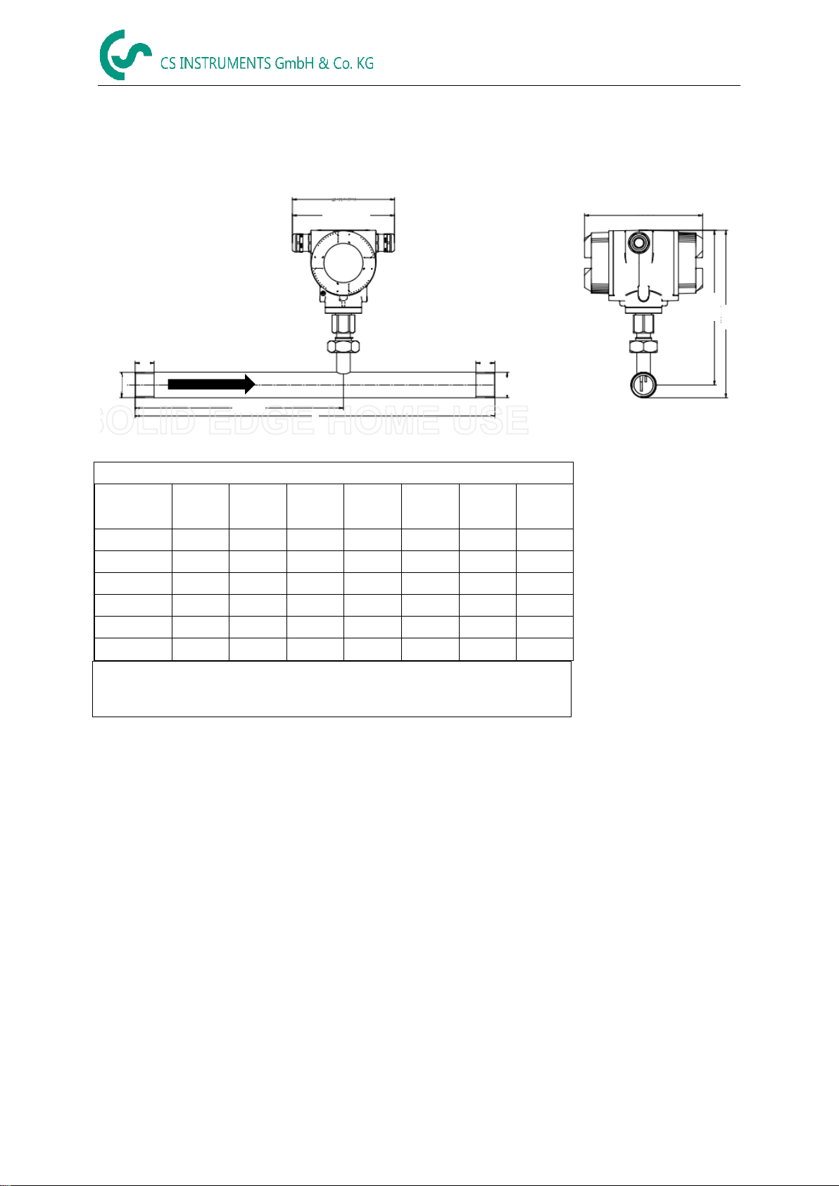
5 Dimensions
5.1 Dimension VA 570 Thread-version
VA 570 thread version
Connection
thread
Outer
pipe dia.
[mm]
Inner
pipe dia.
[mm]
L
[mm]
L1
[mm]
H
[mm]
H1
[mm]
A
[mm]
1/2“
21,3
16,1
300
210
228
218
20
3/4“
26,9
21,7
475
275
231
218
20
1“
33,7
27,3
475
275
235
218
25
1 1/4“
42,4
36
475
275
239
218
25
1 1/2“
48,3
41,9
475**
275
242
218
25
2“
60,3
53,1
475**
275
248
218
30
** Attention: Shortend inlet section! Please observe the recommended minimum inlet section
(length = 10x inner diameter)
138 (max) Ex Version
132 (max)
156 (max)
A
A
D1
D1
L
A
L1
A
H1
H
Flow direction

Dimension
VA 570 English V1.19 Page 12 of 44
5.2 Dimension VA 570 Flanged-version
VA 570 flanged version
Flange DIN EN 1092-1
Measuring
section
Outer
pipe
dia.
[mm]
Inner
pipe
dia.
[mm]
L
[mm]
L1
[mm]
H
[mm]
H1
[mm]
ØD
[mm]
ØK
[mm]
n x ØL
DN 15
21,3
16,1
300
210
267
218
95
65
4 x 14
DN 20
26,9
21,7
475
275
270
218
105
75
4 x 14
DN 25
33,7
27,3
475
275
275
218
115
85
4 x 14
DN 32
42,4
36
475
275
288
218
140
100
4 x 18
DN 40
48,3
41,9
475**
275
293
218
150
110
4 x 18
DN 50
60,3
53,1
475**
275
300
218
165
125
4 x 18
DN 65
76,1
68,9
475**
275
320
228
185
145
8 x 18
DN 80
88,9
80,9
475**
275
328
228
200
160
8 x 18
** Attention: Shortened inlet section! Please observe the recommended minimum inlet section (length = 10x inner diameter)
138 (max) Ex Version
132 (max)
156 (max)
H1
H
L
L1
Flow direction

Installation
VA 570 English V1.19 Page 13 of 44
6 Installation
6.1 Pipe/tube requirements
•Correctly sized gaskets
•Correct aligned flanges and gaskets
•Diameter mismatch at the pipe junctions should be avoided but must be less than 1mm.
For further information see ISO 14511
•Ensure clean pipes after installation
6.2 Inlet / outlet runs
The principle of thermal Mass flow measurement is very sensitive against disturbances. Therefore, it is
necessary to ensure the recommended inlet and outlet runs.
Table Inlet / Outlet runs
Flow obstruction before the measurement
section
Min length
Inlet run (L1)
Min length
Outlet run (L2)
Slight curve
(ellbow < 90°)
12 x D
5 x D
Reduction
(Pipe narrows to the measurement section)
15 x D
5 x D
Expansion
(Pipe expands to the measurement section)
15 x D
5 x D
90° ellbow or T-piece
15 x D
5 x D
2x ellbow á 90°
in einer Ebene
20 x D
5 x D
2x ellbow á 90°
3-dimensional
35 x D
5 x D
Control valve
45 x D
5 x D
15 x D 5 x D
15 x D 5 x D15 x D
15 x D 5 x D
20 x D 5 x D
35 x D 5 x D
5 x D45 x D
The values represent the min.lenghts. In case the min. inlet / outlet runs could not be ensured, it must
be expected to get increased or significant deviations of the measurement values.
Installation
VA 570 English V1.19 Page 14 of 44
6.2.1 Installation of VA 570
The sensor VA 570 is pre-supplied with the measuring section.
An installation at customer site is only allowed in the unpressurized state of the
system
The connecting nut is tightened to a torque of 25 -30 Nm.
Tightness of the connection must be checked and ensured.
Important: Please check flow direction, see therefore label on measuring section and pictures
of chapter 5.1 and chapter 5.2
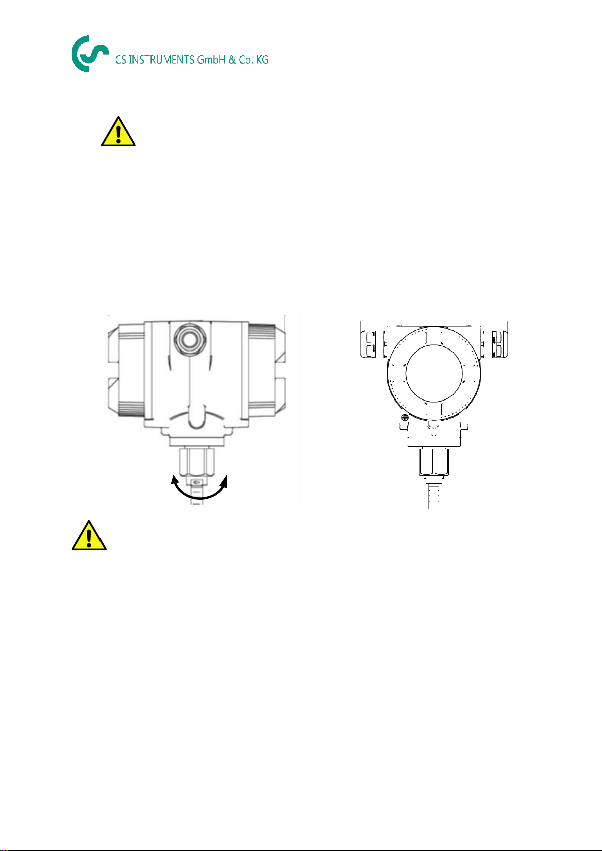
6.3 Alignment Display (Housing)
The sensor housing VA 570 can be turned in both directions, max. 345 °. For this purpose, the
housing-connecting nut must be opened. The housing can be rotated to the desired position, a bigger
rotaion angle is prevented by internal stop pins.
After that, the housing-connecting nut is firmly retighten
Housing
connection nut
Loosen the housing connection nut only, do not unscrew it
completely!

Installation
VA 570 English V1.19 Page 15 of 44
6.4 Tightening torques
To secure and guarantee of the function and tightness following tightening torques have to be
applied, see table 1.
Description
Tightening torque
[Nm]
VA570 Cover with glass
3
VA570 Cover closed
3
Grub screw with hexagon socket M4x6 DIN 914 A2
2
Housing connection nut
15
Cable glands
8
Table 1
Wiring
VA 570 English V1.19 Page 16 of 44
7 Connection diagram
7.1 Cable glands - clamping ranges
For ensuring the tightness and strain relief, connector cables with the following diameters must be
used.
VA570 Standard clamping range : Ø5-9mm
VA570 Ex clamping range: Ø5-10mm
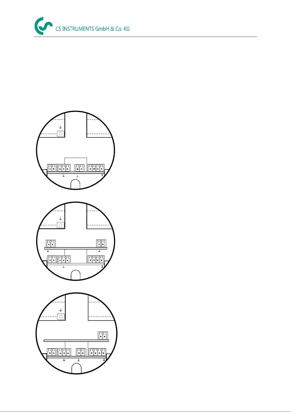
7.2 Connector pin assignment
Pulse
12
I (4-20mA)
X1 X2 X3
12
GND
VB+
1 2 3
Mod(A)
1 2 3 4
Pulse
DIR
Main Board
Mod(B)
X4
Standard version with 1x analogue output (not galvanically
isolated)
Pulse
12
I (4-20mA)
12
X1 X2 X4
X6
X5
I (4-20mA)
12
GND
VB+
1 2 3
Mod(A)
1 2 3 4
Pulse
DIR
Main Board
Mod(B)
Option Board 4-20mA
Version with option board 2x analogue outputs galvanically
isolated
Pulse
21
X1 X2 X4
K1
MBUS
12
GND
VB+
1 2 3
Mod(A)
1 2 3 4
Pulse
DIR
Main Board
Mod(B)
Option Board MBus
I ( 4...20mA)
X3
Version with option board MBus

Wiring
VA 570 English V1.19 Page 17 of 44
Connector
Pin
Signal description
X1
Power
supply
1
VB - (GND)
2
VB+
X2
Modbus
1
Modbus (B)
2
Modbus shield
3
Modbus (A)
X3
urrent output
1
I- Active
2
I+ Active
X4
Direction / Pulse
1
Pulse / Alarm *
2
Pulse / Alarm *
3
Direction input
4
GND
X5
Current output
1
1
I- Active**
2
I+ Active **
X6
Current output
2
1
I- Active **
2
I+ Active **
K1
MBus
1
MBus
2
MBus
* Outputs are galvanically isolated.
** The Current outputs, X5 and X6, are optional.(Active and passive version
available).
Wiring
VA 570 English V1.19 Page 18 of 44
7.3 Wire connection
7.3.1 General:
•Wiring to be done in strainless state only.
•Length of cable skinning to be minimized
•Not used cable entries must be closed with end caps
•Use of cables with cross section of >= 0.25mm²
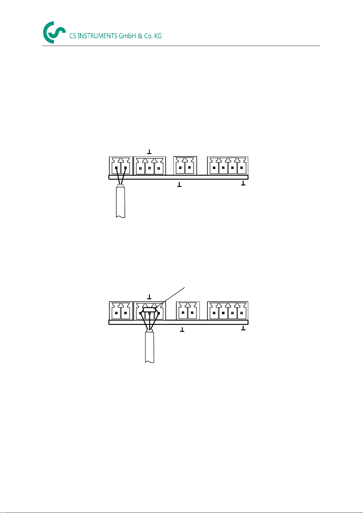
7.3.2 Power supply
Pulse
X1 X2
X4
12
GND
VB+
1 2 3
Mod(A)
1 2 3 4
Pulse
DIR
Main Board
Mod(B)
12
I (4...20mA)
X3
7.3.3 Modbus RTU
If the sensor placed at the end oft he Modbus system a termination is required.
Therfore the enclosed 120R resistor ist o be connected at Pin 1 and Pin 3 of connector „X2“
Pulse
X1 X2
X4
12
GND
VB+
1 2 3
Mod(A)
1 2 3 4
Pulse
DIR
Main Board
Mod(B)
120R
Terminierung Modbus
12
I (4...20mA)
X3

Wiring
VA 570 English V1.19 Page 19 of 44
7.3.4 Modbus TCP (Ethernet) Optional PoE
M12 x-coded
Data LINES: 1,2 und 3,4
PoE LINES: 5,6 und 7,8
2
81
3
5 4
6
7
M12 x 1
Connection cable: Cat 6.
*PoE: Power over Ethernet
7.3.5 Pulse Output
Pulse
X1 X2
X4
12
GND
VB+
1 2 3
Mod(A)
1 2 3 4
Pulse
DIR
Main Board
Mod(B)
Potentialfreier
Schaltkontakt
Max. 48Vdc , 500mA
12
I (4...20mA)
X3
Operation
VA 570 English V1.19 Page 20 of 44
8 Operation VA 570
Remark: Only for version with display
The operation of the VA 570 are carried out by 2 optical keys through the glass cover Thus, the VA 570
can be operated from the outside without opening the cap.
OK
OK
Optical keys
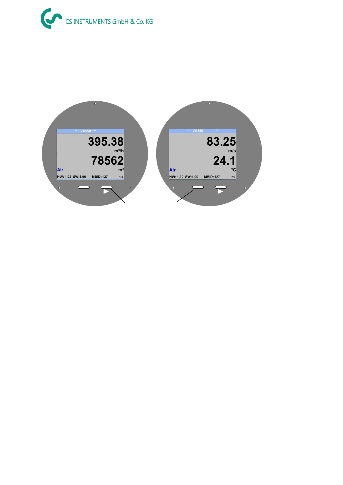
Selection of the individual menu items is done by pressing the ">" and confirm by pressing "OK".
Inputs or changes can be made with all white deposit fields, selcted filed will be highlighted with yellow
background.
Words in green font refer mainly to the pictures in the section of the chapter, but also on important menu
paths or menu items that are related to are in green font.
The menu navigation is generally in a green font!
The table of contents and chapter references in blue font contain links to the respective chapter title.
Table of contents
Other CS Instruments Accessories manuals

CS Instruments
CS Instruments VA 452 User manual

CS Instruments
CS Instruments FA 550 User manual

CS Instruments
CS Instruments VD 500 User manual

CS Instruments
CS Instruments VA 500 User manual

CS Instruments
CS Instruments Vortex VX 570 User manual

CS Instruments
CS Instruments VA 500 User manual

CS Instruments
CS Instruments VA 521 User manual

CS Instruments
CS Instruments VA 525 User manual

CS Instruments
CS Instruments VA 400 User manual

CS Instruments
CS Instruments VA 550 User manual


