CS Instruments VA 452 User manual

0970 0042 VA 452 English, V1.9, 13.08.13 0970 0042 VA 452 English, V1.9, 13.08.13
Flow sensor VA 452 Flow sensor VA 452
VA 452
thermal mass flow sensor
Operating Instruction
11A Floor, D3 Building, TCL International E City, No. 1001
Zhongshanyuan Road, Nanshan District,
Shenzhen 518057, China
Tel: +86 (0)755 - 8619 3164
Fax: +86 (0)755 - 8619 3165
Website: http://www.csinstrument.com
CS Instruments (Shenzhen) Co. Ltd.
Room 1506, Hong Qiao Silver City Building, No.933
Zhongshan Road(w), Shanghai 200051, China.
Tel: +86 (0) 21-5111 3860
Fax: +86 (0) 21-5111 3861
Website: http://www.csinstrument.com
CS Instruments (Shanghai) branch
Asia Head Quarters
Room 31, Tower B, Cambridge Plaza,188 San Wan Road,
Sheung Shui, N.T. , Hong Kong
Tel: +86 (0)755 - 8619 3164
Fax: +86 (0)755 - 8619 3165
Website: http://www.csinstrument.com
CS Instruments (Asia) Co. Ltd.
Shanghai office
Hong Kong office

0970 0042 VA 452 English, V1.9, 13.08.13 0970 0042 VA 452 English, V1.9, 13.08.13
Flow sensor VA 452 Flow sensor VA 452
2
Table of Contents
Chapter 1 General Information
23
Chapter 2 Introduction
Chapter 3 Installation
Important information………………………………………………………...……....3
Area of application…………………………………………………………...……….3
Installation considerations………………………………………………...………....3
Notes on safety…………………………………………….……..…………………..4
Product feature……………………...…………………………………..……….…...5
Inlet / outlet runs…………………………………………..…….………………..…..5
Flow conditioner……………………………………………………………………....6
Pipe requirements……………………………………………...……….…………....7
Installation…………………………………………………………………...………...7
Wiring……………………………………………………...…………..……………..10
Connection diagram…………………………………………………………...……10
Connecting DS 300 ………………………………………...……...………..…..…11
Connecting analogue / pulse outputs………………………………….……….…12
Connecting HART………………………………………………...………….…..…12
Connecting Modbus …………………….……………………...…………….....…12
Connecting MBus ………………………………...………...…………………...…13
Chapter 4 Operation
Chapter 5 Trademarks………………….………………...……......……...….
21
Chapter 6 Warranty………………………………………………………..…..
21
Startup…………………………………………………...………...……..……...…..14
Display…………………………………………………...……………………..……14
Configuration…………………………………………………...…….………..….…15
Bluetooth…………………………………………………...……………………..….16
Service Kit…………………………………………………...…………………....…16
Technical data…………………………………………………...……………..…...17
Measuring…………………………………………………...………...………....….17
Dimensions …………………………………………………...…………………..…20

0970 0042 VA 452 English, V1.9, 13.08.13 0970 0042 VA 452 English, V1.9, 13.08.13
Flow sensor VA 452 Flow sensor VA 452
The operating instructions must be read in full and carefully ob-
served before starting up the device. The manufacturer cannot be
held liable for any damage which occurs as a result of non-
observance or non-compliance with this manual.
Should the device be tampered with in any manner other than a
procedure which is described and specified in the manual, the war-
ranty is cancelled and the manufacturer is exempt from liability.
CS Instruments is not liable for errors which may have slipped into
this operating manual.
The CS flow meter VA 452 works based on the thermal mass flow
principle and is to be used for measuring the mass flow of gases.
The device can be configured to measure pure gases (e.g. CO2, N2,
O2, Ar etc.) or gas mixtures (e.g. air, natural gas). It is used to meas-
ure gas/air consumption, control and monitor flow rates.
Any use other than that described here compromises the safety of
persons and the entire measuring system and is, therefore, not per-
mitted.
The manufacturer is not liable for damage caused by improper or
non-designated use.
Important
information
Area of
application
322
Installation
and operation
The measuring device must only be installed, connected, commis-
sioned and maintained by qualified and authorized specialists (e.g.
electrical technicians) in full compliance with the instructions in this
manual, the applicable norms, legal regulations and certificates
(depending on the application).
The measuring device may only be modified or repaired if such work
is permitted in this instruction manual.
In order to achieve and maintain the accuracy stipulated in the tech-
nical data, the sensor must be installed according to the instructions
in this manual.
Unhindered flow characteristics are achieved if the sections in front
of the sensor (inlet) and behind the sensor (outlet) are sufficiently
long, absolutely straight and without obstructions such as edges,
seams, bends etc.
Careful attention must be paid to the design of the outlet section as
obstructions can cause counter-flow turbulence as well as turbu-
lence in the direction of the flow.
1. General information

0970 0042 VA 452 English, V1.9, 13.08.13 0970 0042 VA 452 English, V1.9, 13.08.13
Flow sensor VA 452 Flow sensor VA 452
•
VA 452 is designed to meet state-of-the-art safety require-
ments, has been tested, and left the factory in a condition in
which it is safe to operate. Relevant regulations and European
standards have been observed.
•
The wiring of the device has to be done correctly in accord-
ance with the wiring diagrams.
•
Observe the technical data on the nameplate!
•
Do not exceed the pressure range of 4.0 MPa.
•
Observe permissible storage, transport and operating tempera-
tures.
•
VA 452 for use in hazardous areas are labeled accordingly on
the nameplate. Relevant national regulations must be ob-
served when operating the device in hazardous areas. Ob-
serve the installation regulations, connection data and safety
instructions provided in the Ex documentation must be ob-
served.
Notes on
safety
4 21
CS provides a warranty for this product of 24 months covering the
material and workmanship under the stated operating conditions
from the date of delivery.
Please report any findings immediately and within the warranty
time guaranteed by us.
Excluded from this warranty is damage caused by improper use
and non-adherence to the instruction manual.
The warranty is also cancelled once the measuring instrument has
been opened provided this is not described in the instruction man-
ual for maintenance purposes. This is also the case if the serial
number has been changed, damaged or removed.
If in addition to the warranty service necessary repairs, adjust-
ments or similar are carried out, the warranty services are free of
charge but there is a charge for other services such as transport
and packing costs. Other claims, especially those for damage
occurring outside the instrument are not included unless responsi-
bility is legally binding.
Warranty
HART®
Registered trademark of HART Communication Foundation, Austin,
USA
MODBUS®
Registered trademark of the MODBUS Organization
MBUS®
Registered trademark of the MBUS Organization
Bluetooth®
Registered trademark of the Bluetooth Organization
Trademarks
6. Warranty
5. Trademarks

0970 0042 VA 452 English, V1.9, 13.08.13 0970 0042 VA 452 English, V1.9, 13.08.13
Flow sensor VA 452 Flow sensor VA 452
5
Product
features
•
Direct measurement of mass flow and standard flow without
the need of pressure compensation
•
Wide range of tube sizes are supported with insertion type
for big tubes and inline types for small tubes
•
No moving parts, non clogging
•
All parts which come into contact with the measurement
medium are made of stainless steel 316L.
•
Robust metal enclosure suitable for out-door applications in
harsh environment
•
Wireless Bluetooth interface for commissioning on site
•
Display showing flow rates, consumption, medium tempera-
ture and diagnostic results
•
2 analogue outputs (4-20 mA) and 1 pulse output
•
Available options:
•
Fieldbus interface: HART, Modbus, MBus
•
Hazardous approval ATEX: II 2 G Ex IIC T4
•
2-directional measurement
•
Flow conditioning
20
inlet / outlet
runs
Thermal mass flow meters are sensitive disturbances in the flowing
gas stream (e.g. vortex formation). As a general rule, the installed
sensor should always be installed as far away as possible from any
flow disturbances . Further information can be found in ISO Standard
14511.
Please observe the following recommended minimum values with
regard to the inlet and outlet runs.
2. Introduction
Dimensions
Pipe
nominal
size
[inch]
Outer diameter x
thickness/[inner dia]
[mm]
L
total
length
[mm]
L1
inlet
length
[mm]
H
total
height
[mm]
H1 from
pipe
center to
casing
top [mm]
1/2" Ø21.3 x 2.6/[Ø16.1] 300 210 247.65 200.15
3/4" Ø26.9 x 2.6/[Ø21.7] 475 275 252.65 200.15
1" Ø33.7 x 3.2/[Ø27.3] 475 275 257.65 200.15
1 ¼" Ø42.4 x 3.2/[Ø36.0] 475 275 270.15 200.15
1 ½" Ø48.3 x 3.2/[Ø41.9] 475 275 275.15 200.15
2" Ø60.3 x 3.6/[Ø53.1] 475 275 282.65 200.15
2 ½" Ø76.1 x 3.6/[Ø68.9] 475 275 300.55 208.05
3" Ø88.9 x 4.0/[Ø80.9] 475 275 314.45 214.45
DN
DN15
DN20
DN25
DN32
DN40
DN50
DN65
DN80

0970 0042 VA 452 English, V1.9, 13.08.13 0970 0042 VA 452 English, V1.9, 13.08.13
Flow sensor VA 452 Flow sensor VA 452
6 19
Flow
conditioner
In areas where the required inlet / outlet rungs can not be achieved
it’s recommended to use a flow conditioner upstream of the sensor.
This will reduce the minimum inlet run to 5-8 x D.
Pressure loss calculation:
DP = K * v
2
* ρ
DP: Pressure loss [hPa or mbar]
K: Constant = 0.008
v: Actual velocity of gas at conditioner inlet [m/s]
ρ: Density of gas [kg/m3]
conditioner
gasket
gasket
Device type: Slave
Polling address: 1 to 15
Bus address can be set through software
Physical interface: BELL 202
Protocol version: V5.2
Tag: VA 452
Tag description: FLOW METER
Frame/parity/Stop: 8, O, 1
HART
Device type: Slave
Address range: 1 to 247
Bus address can be set through software
Physical interface: RS485 in accordance with EIA/TIA-485
standard
Baudrates: 1200, 2400, 4800, 9600, 19200, 38400, 57600,
115200 Baud
Transm. mode: ASCII, RTU
Response times: Direct data access = 0 to 255 ms (can be con
figured)
Modbus
MBus
Approvals
Certificates
CE mark: The measuring system is conform with the
statutory requirements of the EC Directives.
CS Instruments has successful tested the
device and affixed the CE mark.
Ex approval: CS Instruments provides a separate
documentation.
Other
Standards
EN 60529 Protection by housing (IP code)
IEC/EN 61326 EMC- requirements
ISO 14511 Thermal mass flowmeters.
NAMUR NE 43 Standardization analogue outputs
Device type: Slave
Address range: 1 to 251
Bus address can be set through software
Physical interface: Meter-Bus, EN1434-3
Baudrates: 300, 2400, 9600 Baud
Frame/parity/Stop: 8, E, 1

0970 0042 VA 452 English, V1.9, 13.08.13 0970 0042 VA 452 English, V1.9, 13.08.13
Flow sensor VA 452 Flow sensor VA 452
718
Installation
1. Orientation
Pipe
requirements
At all times good installation practice should be followed:
•
Clean pipes and flange welded joints
•
Correctly sized gaskets
•
Correctly aligned flanges and gaskets
•
Use seamless pipes immediately upstream of the flowme-
ter.
•
Use of pipes that match in regards of the internal diameter
next to the flowmeter. Avoid any disturbance or miss-
alignment greater than 1 mm.
•
Anything that disturbs the smoothness of the internal pipe
wall (see figure below) should be eliminated; the goal
should be a smooth uninterrupted internal surface. For
further information please refer to ISO 14511.
3. Installation
Accuracy
Uncertainty: 1.5% of reading + 0.3% of full scale
Repeatability: 0.25 % of reading
Stated uncertainty at:
Ambient / process temperature: 23 °C ± 3 °C
Ambient / process humidity: <90%, no condensation
Process pressure: 0.6 MPa
Response /
Sampling
Response time: T
95
< 5 seconds
Sampling rate: 5 samples per second
Display is refreshed every 0.5 seconds
Outputs are refreshed every 0.2 seconds
Process
connection
R thread (ISO 7-1), Flange EN 1092-1
All parts in contact with the medium are of stainless steel 316L
Power supply
16 - 30 VDC, 7 W
Environment
conditions
Ambient temp.: -30 … +65 °C (non display version)
-25 … +65 °C (display version)
Storage temp.: -40 … +65 °C
Protection: IP 67
Shock resistance: IEC 60068-2-31
Vibration resist.: IEC 60068-2-6
EMC: IEC / EN 61326
Operating
conditions
Medium temp.: -40 … +100 °C
Pressure loss: < 3 hPa (4” pipe)
Medium pressure: -0.1 … 4.0 MPa
Analogue
output
Active / passive selectable, galvanic isolated
Active: 4 to 20 mA, RL < 400 Ω
Passive: 4 to 20 mA; supply voltage 1 ! 30 V DC, RL <
500 Ω
for HART: RL ≥250 Ω
Uncertainty: < 0.3% of reading
Resolution: 0.005 mA
Pulse/Alarm
output
NO switch, no polarity required, galv. isolated
Max rating: 30 VDC, 200 mA
Pulse width: 10 … 100 msec (depending on flow rate)
Communication Distance: < 3m (depend on environment)
Device name: VA 452 + s/n (Can be edited)
Bluetooth
DN 15 (1/2”), DN 20 (3/4”), DN 25 (1”), DN 32 (1 ¼”),
DN 40 (1 ½”), DN 50 (2”), DN 65 (2 ½”), DN 80 (3”)
Tube size
0970 0042 VA 452 English, V1.9, 13.08.13 0970 0042 VA 452 English, V1.9, 13.08.13
Flow sensor VA 452 Flow sensor VA 452
8 17
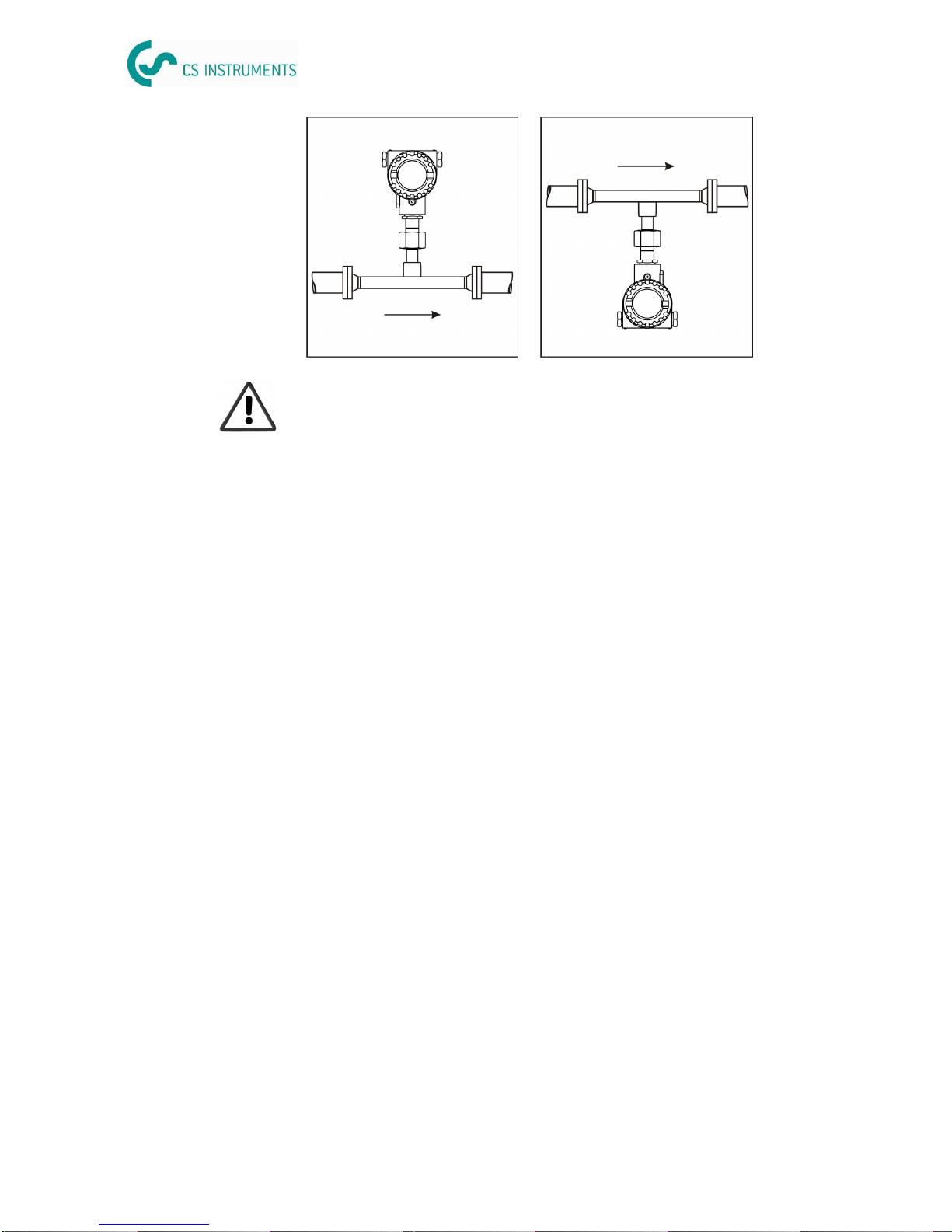
The unit can be installed in any position in the piping. In the case of
wet/dirty gases, upward flow is recommended in vertical pipes to
minimize condensation/contamination on or around the sensing
element. In particular, where free condensation can occur (e.g. Bio-
gas) the sensor should be orientated to prevent water collecting on
or around the sensing elements (e.g. do not install the sensor at a
low point in the installation without adequate drainage).
Ensure that the direction arrow on the sensor matches the direction
of flow .
2. Display orientation
The display version of VA 452 can be rotated in both directions
270°. For this purpose the the nut at the top of the shaft has to be
opened fully. Then pull up the metal casing and rotate it in the de-
sired direction. It can be rotated in 90°steps in both directions. A
metal pin locks the position. When the desired position is achieved,
press down the metal casing onto the shaft so that the metal pin can
insert into the position hole. Tighten up the nut.
Technical
data
Measuring
range
Pipe sm
3
/h kg/h
Inch DN mm Min Max Min Max
1" DN25 27.3 0.6 147.7 0.7 175.5
1 1/4" DN32 36.0 1.1 266.3 1.3 316.5
1 1/2" DN40 41.9 1.5 366.7 1.7 435.9
2” DN50 53.1 2.4 600 2.9 713
2 1/2" DN65 68.9 4.1 1027 4.9 1220
3” DN80 80.9 5.7 1424 6.8 1693
3/4” DN20 21.7 0.4 89.1 0.4 105.9
1/2” DN15 16.1 0.2 45.6 0.2 54.2
Volumetric flow is stated at 1000 hPa and 20 °C
VA 452 can measure from zero flow onwards, the stated minimum
flow is only required for achieving the specification. Flow rates above
the maximum flow can not be measured.
Standard range calibration:
Pipe sm
3
/h kg/h
Inch DN mm Min Max Min Max
1" DN25 27.3 1.2 294.7 1.4 350.3
1 1/4" DN32 36.0 2.1 531.5 2.5 631.7
1 1/2" DN40 41.9 2.9 731.9 3.5 869.9
2” DN50 53.1 4.8 1198 5.7 1423
2 1/2" DN65 68.9 8.2 2049 9.7 2435
3” DN80 80.9 11.4 2841 13.5 3377
3/4” DN20 21.7 0.7 177.8 0.8 211.4
1/2” DN15 16.1 0.4 100.0 0.4 108.1
Max range calibration:

0970 0042 VA 452 English, V1.9, 13.08.13 0970 0042 VA 452 English, V1.9, 13.08.13
Flow sensor VA 452 Flow sensor VA 452
16 9
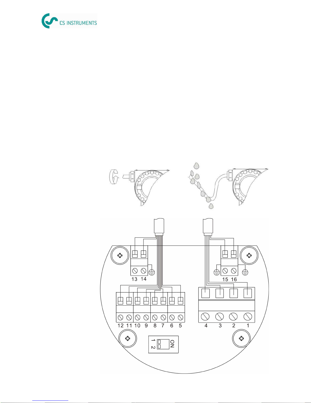
3. Protect sensor tip
The sensor unit can be removed from the measuring section for
example for cleaning or service / calibration. To protect the sensor
during transportation we recommend to use a sensor protection cap
as indicated in the picture below.
Please contact our local service for sensor protection cap.
Sensor head can be rotated in 90°steps through the screw nut
Power
supply
PC VA 452
Bluetooth
Power
supply
PC VA 452Service
Kit
Bluetooth
Bluetooth provides a convenient way of configuring the sensor with-
out the hazel of cable connections. VA 452 needs to be powered up.
Ensure that the distance between VA 452 and PC is no more that 5
meter and the PC Bluetooth antenna should point roughly in the
direction of the display (front part). Please follow the instruction in
the service software and the help file.
Service Kit
The diagram above shows the connection when using the optional
service kit (0554 2005). Please ensure that also in this case the
power supply of either VA 452 or of the service kit is connected
(USB port is not supplying enough power).
0970 0042 VA 452 English, V1.9, 13.08.13 0970 0042 VA 452 English, V1.9, 13.08.13
Flow sensor VA 452 Flow sensor VA 452
10 15
When installing the cables please consider following points:
•
Keep the stripped and twisted lengths of cable shield as
short as possible.
•
Screen and ground the signal lines
•
Install the measuring device that the cable entries do not
point upwards.
•
Do not remove the seal from the cable entry.
•
Unused cable entries must be closed with closers.
•
Cable outer diameter should be between 6 and 8 mm
•
Single wire cross section area should be between 0.25 …
0.75 mm
2
•
The thread size for the cable glands is M20 / 1.5
Wiring
Connection
diagram
Configuration
Configuration settings have to be done through the service software
which is included in the scope of delivery. The service software can
be isntalled on any PC with windows operating system. To
communicate with the sensor the PC needs to have a Bluetooth
interface. Alternativly a service kit can be used which cis as option
Area Available settings Default
Measurement Tube diameter
Flow unit
Consumption unit
Reference conditions
Gas type selection
Consumption counter
Operation pressure
Flow direction
54.0
m
3
/h
m
3
P
S
= 1000 hPA
T
S
= 20 °C
Air
0 m
3
0.6 MPa
Standard
Analogue
output 1 Measurement channel
Scaling
Active / passive
Flow
4 mA: 0 m
3
/h
20 mA: max flow
Active
Pulse output Pulse / Alarm
Pulses per consumption unit Pulse
1
HART Fieldbus address
Manufacturer ID
Device type code
0
255
0
Modbus Device address
Baudrate
Framing/parity/Stop bit
Transmission mode
1
19200
8, E, 1
RTU
MBus Address
Manufacturer code
Baudrate
Access Number
0
END
300
0
Analogue
output 2 Measurement channel
Scaling
Active / passive
Medium Temp.
4 mA: -50 °C
20 mA: 200 °C
Active
In order to fully utilize ethe functionality of VA 452 a configuration is
required. There are various paramters which need to be set in the flow
meter. The table below gives an overview about the available settings.
0970 0042 VA 452 English, V1.9, 13.08.13 0970 0042 VA 452 English, V1.9, 13.08.13
Flow sensor VA 452 Flow sensor VA 452
1114
Connecting
DS 300
DS 300 is connected to VA 452 through a 3 pole cable.
VA 452 DS 300
Pin Signal Pin Pin
4 SDI I-3 G-6
2 V+ I-1 G-8
3 V- I-4 G-7
DS 300 has 2 inputs (I and G) for flow / dew point sensors.
If there are more than 1 VA 452 to be connected to DS 300 a sepa-
rate power supply has to be used for at least one of the VA 452,
since DS 300 can only supply one VA 452 flow sensor.
VA 452 DS 300 Ext. 24 VDC
Pin Signal Pin Pin
4 SDI I-3 G-6
2 V+ N.C. N.C. 24V+
3 V- I-4 G-7 24V-
Startup
Initializing...
2 sec.
Software: 1.31
Hardware: 1.20
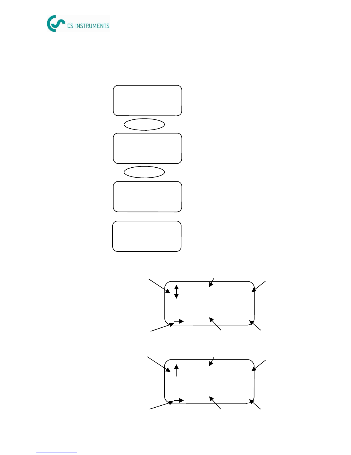
The version with display will startup in the sequence as described
below.
1345.6
12345670
m
3
/h
2 sec.
Software and hardware version
VA 452 will then show the actual online
values of flow and total consumption.
After reset the sensor has a warm-up
time of about 20 seconds., during this
time the flow rate is zero.
m
3
M: 43.6 °C
A: 25.7 °C
E: 00 00 00 00
Every 5 seconds the display will show the
medium and the ambient temperature
together with an error code. The error
code information is helpful for service
engineers .
Display
Flow unit
Consumption unit10 digit consumption
6 digit flow
Flow direction
Overflow indication
12345.6
1234567890
m
3
m
3
/h
4. Operation
Flow unit
Consumption unit10 digit consumption
6 digit flow
Flow direction
Alarm indication
12345.6
1234567890
m
3
m
3
/h
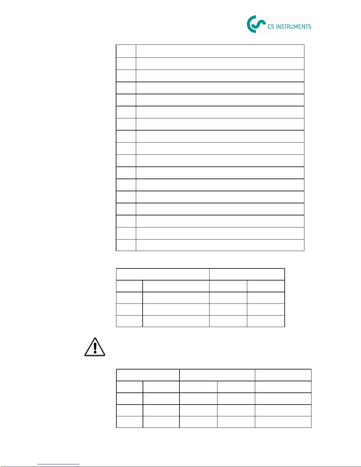
Pin Signal description
1 Ground for SDI
2 V+
3 V-
4 SDI
5 Direction input D1 (flow switch)
6 Direction input D2 (flow switch)
7 Pulse output P1 / Alarm switch A1
8 Pulse output P2 / Alarm switch A2
9 Current output channel 1 - / HART bus
10 Current output channel 1 + / HART bus
11 Current output channel 2 - / MODBUS data + / MBUS M1
12 Current output channel 2 + / MODBUS data - / MBUS M2
13 Ground for MODBUS cable
14 Earth
15 Earth
16 Earth

0970 0042 VA 452 English, V1.9, 13.08.13 0970 0042 VA 452 English, V1.9, 13.08.13
Flow sensor VA 452 Flow sensor VA 452
12 13
Connecting
analogue /
pulse outputs
VA 452 in the standard configuration comes with 2 analogue outputs
and 1 pulse output. All signals are electrically isolated. The analogue
output can be used as an active output—current is sourced through
the positive connection pin—or passive. In the passive configuration
a current signal is modulated onto the external signal voltage.
Pin Signal Description
12 Analog 2 I+ Positive signal output
11 I- Negative signal output
10 Analog 1 I+ Positive signal output
9 I- Negative signal output
7 Pulse P1 No polarity required
8 P2 No polarity required
Connecting
HART
Pin Signal Description
10 Analog 1 I+ / HART+ Positive signal output
9 I- / HART- Negative signal output
The HART signal is modulated on analogue output 1. In case VA
452 is used in a multi drop configuration (more than 1 slave on the 4-
20 mA line) the analogue output can not be used anymore.
Connecting
Modbus
The version with Modbus comes with one analogue output
and one pulse output.
Pin Signal Description
11 Modbus Data+ RS-485
12 Data- RS-485
10 Analog 1 I+ Positive signal output
9 I- Negative signal output
7 Pulse P1 No polarity required
8 P2 No polarity required
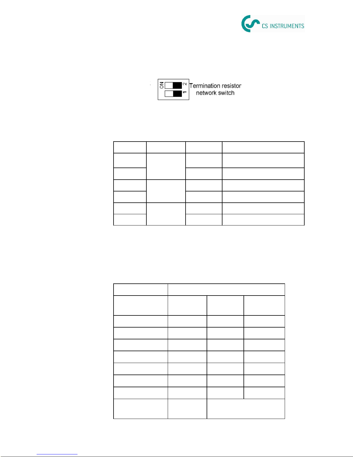
Modbus requires to activate terminal resistors at the last device on
the bus system. For this purpose the DIP switches on the connector
board should be set to “ON” position.
Connecting
MBus
The version with MBus comes with one analogue output and one
pulse output.
Pin Signal Description
11 MBus M1 MBus
12 M2 MBus
10 Analog 1 I+ Positive signal output
9 I- Negative signal output
7 Pulse P1 No polarity required
8 P2 No polarity required
Pulse output
The maximum number of pulses per second is limited to 45 pulse
per second. As a result depending on the flow rate and the selected
consumption unit the maximum flow rate is limited to the values in
the table below..
Unit Max flow
Pulses per con-
sumption unit 1 1/10 1/100
m3/h 162,000 1,620,000 16,200,000
m3/min 2,700 27,000 270,000
l/min 2,700 27,000 270,000
cfm 2,700 27,000 270,000
Kg/h 162,000 1,620,000 16,200,000
Kg/min 2,700 27,000 27,0000
Kg/s 45 450 4,500
Default To be configured by ser-
vice software
0970 0042 VA 452 English, V1.9, 13.08.13 0970 0042 VA 452 English, V1.9, 13.08.13
Flow sensor VA 452 Flow sensor VA 452
12 13
Connecting
analogue /
pulse outputs
VA 452 in the standard configuration comes with 2 analogue outputs
and 1 pulse output. All signals are electrically isolated. The analogue
output can be used as an active output—current is sourced through
the positive connection pin—or passive. In the passive configuration
a current signal is modulated onto the external signal voltage.
Pin Signal Description
12 Analog 2 I+ Positive signal output
11 I- Negative signal output
10 Analog 1 I+ Positive signal output
9 I- Negative signal output
7 Pulse P1 No polarity required
8 P2 No polarity required
Connecting
HART
Pin Signal Description
10 Analog 1 I+ / HART+ Positive signal output
9 I- / HART- Negative signal output
The HART signal is modulated on analogue output 1. In case VA
452 is used in a multi drop configuration (more than 1 slave on the 4-
20 mA line) the analogue output can not be used anymore.
Connecting
Modbus
The version with Modbus comes with one analogue output
and one pulse output.
Pin Signal Description
11 Modbus Data+ RS-485
12 Data- RS-485
10 Analog 1 I+ Positive signal output
9 I- Negative signal output
7 Pulse P1 No polarity required
8 P2 No polarity required
Modbus requires to activate terminal resistors at the last device on
the bus system. For this purpose the DIP switches on the connector
board should be set to “ON” position.
Connecting
MBus
The version with MBus comes with one analogue output and one
pulse output.
Pin Signal Description
11 MBus M1 MBus
12 M2 MBus
10 Analog 1 I+ Positive signal output
9 I- Negative signal output
7 Pulse P1 No polarity required
8 P2 No polarity required
Pulse output
The maximum number of pulses per second is limited to 45 pulse
per second. As a result depending on the flow rate and the selected
consumption unit the maximum flow rate is limited to the values in
the table below..
Unit Max flow
Pulses per con-
sumption unit 1 1/10 1/100
m3/h 162,000 1,620,000 16,200,000
m3/min 2,700 27,000 270,000
l/min 2,700 27,000 270,000
cfm 2,700 27,000 270,000
Kg/h 162,000 1,620,000 16,200,000
Kg/min 2,700 27,000 27,0000
Kg/s 45 450 4,500
Default To be configured by ser-
vice software
0970 0042 VA 452 English, V1.9, 13.08.13 0970 0042 VA 452 English, V1.9, 13.08.13
Flow sensor VA 452 Flow sensor VA 452
1114
Connecting
DS 300
DS 300 is connected to VA 452 through a 3 pole cable.
VA 452 DS 300
Pin Signal Pin Pin
4 SDI I-3 G-6
2 V+ I-1 G-8
3 V- I-4 G-7
DS 300 has 2 inputs (I and G) for flow / dew point sensors.
If there are more than 1 VA 452 to be connected to DS 300 a sepa-
rate power supply has to be used for at least one of the VA 452,
since DS 300 can only supply one VA 452 flow sensor.
VA 452 DS 300 Ext. 24 VDC
Pin Signal Pin Pin
4 SDI I-3 G-6
2 V+ N.C. N.C. 24V+
3 V- I-4 G-7 24V-
Startup
Initializing...
2 sec.
Software: 1.31
Hardware: 1.20
The version with display will startup in the sequence as described
below.
1345.6
12345670
m
3
/h
2 sec.
Software and hardware version
VA 452 will then show the actual online
values of flow and total consumption.
After reset the sensor has a warm-up
time of about 20 seconds., during this
time the flow rate is zero.
m
3
M: 43.6 °C
A: 25.7 °C
E: 00 00 00 00
Every 5 seconds the display will show the
medium and the ambient temperature
together with an error code. The error
code information is helpful for service
engineers .
Display
Flow unit
Consumption unit10 digit consumption
6 digit flow
Flow direction
Overflow indication
12345.6
1234567890
m
3
m
3
/h
4. Operation
Flow unit
Consumption unit10 digit consumption
6 digit flow
Flow direction
Alarm indication
12345.6
1234567890
m
3
m
3
/h
Pin Signal description
1 Ground for SDI
2 V+
3 V-
4 SDI
5 Direction input D1 (flow switch)
6 Direction input D2 (flow switch)
7 Pulse output P1 / Alarm switch A1
8 Pulse output P2 / Alarm switch A2
9 Current output channel 1 - / HART bus
10 Current output channel 1 + / HART bus
11 Current output channel 2 - / MODBUS data + / MBUS M1
12 Current output channel 2 + / MODBUS data - / MBUS M2
13 Ground for MODBUS cable
14 Earth
15 Earth
16 Earth

0970 0042 VA 452 English, V1.9, 13.08.13 0970 0042 VA 452 English, V1.9, 13.08.13
Flow sensor VA 452 Flow sensor VA 452
10 15
When installing the cables please consider following points:
•
Keep the stripped and twisted lengths of cable shield as
short as possible.
•
Screen and ground the signal lines
•
Install the measuring device that the cable entries do not
point upwards.
•
Do not remove the seal from the cable entry.
•
Unused cable entries must be closed with closers.
•
Cable outer diameter should be between 6 and 8 mm
•
Single wire cross section area should be between 0.25 …
0.75 mm
2
•
The thread size for the cable glands is M20 / 1.5
Wiring
Connection
diagram
Configuration
Configuration settings have to be done through the service software
which is included in the scope of delivery. The service software can
be isntalled on any PC with windows operating system. To
communicate with the sensor the PC needs to have a Bluetooth
interface. Alternativly a service kit can be used which cis as option
Area Available settings Default
Measurement Tube diameter
Flow unit
Consumption unit
Reference conditions
Gas type selection
Consumption counter
Operation pressure
Flow direction
54.0
m
3
/h
m
3
P
S
= 1000 hPA
T
S
= 20 °C
Air
0 m
3
0.6 MPa
Standard
Analogue
output 1 Measurement channel
Scaling
Active / passive
Flow
4 mA: 0 m
3
/h
20 mA: max flow
Active
Pulse output Pulse / Alarm
Pulses per consumption unit Pulse
1
HART Fieldbus address
Manufacturer ID
Device type code
0
255
0
Modbus Device address
Baudrate
Framing/parity/Stop bit
Transmission mode
1
19200
8, E, 1
RTU
MBus Address
Manufacturer code
Baudrate
Access Number
0
END
300
0
Analogue
output 2 Measurement channel
Scaling
Active / passive
Medium Temp.
4 mA: -50 °C
20 mA: 200 °C
Active
In order to fully utilize ethe functionality of VA 452 a configuration is
required. There are various paramters which need to be set in the flow
meter. The table below gives an overview about the available settings.

0970 0042 VA 452 English, V1.9, 13.08.13 0970 0042 VA 452 English, V1.9, 13.08.13
Flow sensor VA 452 Flow sensor VA 452
16 9
3. Protect sensor tip
The sensor unit can be removed from the measuring section for
example for cleaning or service / calibration. To protect the sensor
during transportation we recommend to use a sensor protection cap
as indicated in the picture below.
Please contact our local service for sensor protection cap.
Sensor head can be rotated in 90°steps through the screw nut
Power
supply
PC VA 452
Bluetooth
Power
supply
PC VA 452Service
Kit
Bluetooth
Bluetooth provides a convenient way of configuring the sensor with-
out the hazel of cable connections. VA 452 needs to be powered up.
Ensure that the distance between VA 452 and PC is no more that 5
meter and the PC Bluetooth antenna should point roughly in the
direction of the display (front part). Please follow the instruction in
the service software and the help file.
Service Kit
The diagram above shows the connection when using the optional
service kit (0554 2005). Please ensure that also in this case the
power supply of either VA 452 or of the service kit is connected
(USB port is not supplying enough power).

0970 0042 VA 452 English, V1.9, 13.08.13 0970 0042 VA 452 English, V1.9, 13.08.13
Flow sensor VA 452 Flow sensor VA 452
8 17
The unit can be installed in any position in the piping. In the case of
wet/dirty gases, upward flow is recommended in vertical pipes to
minimize condensation/contamination on or around the sensing
element. In particular, where free condensation can occur (e.g. Bio-
gas) the sensor should be orientated to prevent water collecting on
or around the sensing elements (e.g. do not install the sensor at a
low point in the installation without adequate drainage).
Ensure that the direction arrow on the sensor matches the direction
of flow .
2. Display orientation
The display version of VA 452 can be rotated in both directions
270°. For this purpose the the nut at the top of the shaft has to be
opened fully. Then pull up the metal casing and rotate it in the de-
sired direction. It can be rotated in 90°steps in both directions. A
metal pin locks the position. When the desired position is achieved,
press down the metal casing onto the shaft so that the metal pin can
insert into the position hole. Tighten up the nut.
Technical
data
Measuring
range
Pipe sm
3
/h kg/h
Inch DN mm Min Max Min Max
1" DN25 27.3 0.6 147.7 0.7 175.5
1 1/4" DN32 36.0 1.1 266.3 1.3 316.5
1 1/2" DN40 41.9 1.5 366.7 1.7 435.9
2” DN50 53.1 2.4 600 2.9 713
2 1/2" DN65 68.9 4.1 1027 4.9 1220
3” DN80 80.9 5.7 1424 6.8 1693
3/4” DN20 21.7 0.4 89.1 0.4 105.9
1/2” DN15 16.1 0.2 45.6 0.2 54.2
Volumetric flow is stated at 1000 hPa and 20 °C
VA 452 can measure from zero flow onwards, the stated minimum
flow is only required for achieving the specification. Flow rates above
the maximum flow can not be measured.
Standard range calibration:
Pipe sm
3
/h kg/h
Inch DN mm Min Max Min Max
1" DN25 27.3 1.2 294.7 1.4 350.3
1 1/4" DN32 36.0 2.1 531.5 2.5 631.7
1 1/2" DN40 41.9 2.9 731.9 3.5 869.9
2” DN50 53.1 4.8 1198 5.7 1423
2 1/2" DN65 68.9 8.2 2049 9.7 2435
3” DN80 80.9 11.4 2841 13.5 3377
3/4” DN20 21.7 0.7 177.8 0.8 211.4
1/2” DN15 16.1 0.4 100.0 0.4 108.1
Max range calibration:

0970 0042 VA 452 English, V1.9, 13.08.13 0970 0042 VA 452 English, V1.9, 13.08.13
Flow sensor VA 452 Flow sensor VA 452
718
Installation
1. Orientation
Pipe
requirements
At all times good installation practice should be followed:
•
Clean pipes and flange welded joints
•
Correctly sized gaskets
•
Correctly aligned flanges and gaskets
•
Use seamless pipes immediately upstream of the flowme-
ter.
•
Use of pipes that match in regards of the internal diameter
next to the flowmeter. Avoid any disturbance or miss-
alignment greater than 1 mm.
•
Anything that disturbs the smoothness of the internal pipe
wall (see figure below) should be eliminated; the goal
should be a smooth uninterrupted internal surface. For
further information please refer to ISO 14511.
3. Installation
Accuracy
Uncertainty: 1.5% of reading + 0.3% of full scale
Repeatability: 0.25 % of reading
Stated uncertainty at:
Ambient / process temperature: 23 °C ± 3 °C
Ambient / process humidity: <90%, no condensation
Process pressure: 0.6 MPa
Response /
Sampling
Response time: T
95
< 5 seconds
Sampling rate: 5 samples per second
Display is refreshed every 0.5 seconds
Outputs are refreshed every 0.2 seconds
Process
connection
R thread (ISO 7-1), Flange EN 1092-1
All parts in contact with the medium are of stainless steel 316L
Power supply
16 - 30 VDC, 7 W
Environment
conditions
Ambient temp.: -30 … +65 °C (non display version)
-25 … +65 °C (display version)
Storage temp.: -40 … +65 °C
Protection: IP 67
Shock resistance: IEC 60068-2-31
Vibration resist.: IEC 60068-2-6
EMC: IEC / EN 61326
Operating
conditions
Medium temp.: -40 … +100 °C
Pressure loss: < 3 hPa (4” pipe)
Medium pressure: -0.1 … 4.0 MPa
Analogue
output
Active / passive selectable, galvanic isolated
Active: 4 to 20 mA, RL < 400 Ω
Passive: 4 to 20 mA; supply voltage 1 ! 30 V DC, RL <
500 Ω
for HART: RL ≥250 Ω
Uncertainty: < 0.3% of reading
Resolution: 0.005 mA
Pulse/Alarm
output
NO switch, no polarity required, galv. isolated
Max rating: 30 VDC, 200 mA
Pulse width: 10 … 100 msec (depending on flow rate)
Communication Distance: < 3m (depend on environment)
Device name: VA 452 + s/n (Can be edited)
Bluetooth
DN 15 (1/2”), DN 20 (3/4”), DN 25 (1”), DN 32 (1 ¼”),
DN 40 (1 ½”), DN 50 (2”), DN 65 (2 ½”), DN 80 (3”)
Tube size

0970 0042 VA 452 English, V1.9, 13.08.13 0970 0042 VA 452 English, V1.9, 13.08.13
Flow sensor VA 452 Flow sensor VA 452
6 19
Flow
conditioner
In areas where the required inlet / outlet rungs can not be achieved
it’s recommended to use a flow conditioner upstream of the sensor.
This will reduce the minimum inlet run to 5-8 x D.
Pressure loss calculation:
DP = K * v
2
* ρ
DP: Pressure loss [hPa or mbar]
K: Constant = 0.008
v: Actual velocity of gas at conditioner inlet [m/s]
ρ: Density of gas [kg/m3]
conditioner
gasket
gasket
Device type: Slave
Polling address: 1 to 15
Bus address can be set through software
Physical interface: BELL 202
Protocol version: V5.2
Tag: VA 452
Tag description: FLOW METER
Frame/parity/Stop: 8, O, 1
HART
Device type: Slave
Address range: 1 to 247
Bus address can be set through software
Physical interface: RS485 in accordance with EIA/TIA-485
standard
Baudrates: 1200, 2400, 4800, 9600, 19200, 38400, 57600,
115200 Baud
Transm. mode: ASCII, RTU
Response times: Direct data access = 0 to 255 ms (can be con
figured)
Modbus
MBus
Approvals
Certificates
CE mark: The measuring system is conform with the
statutory requirements of the EC Directives.
CS Instruments has successful tested the
device and affixed the CE mark.
Ex approval: CS Instruments provides a separate
documentation.
Other
Standards
EN 60529 Protection by housing (IP code)
IEC/EN 61326 EMC- requirements
ISO 14511 Thermal mass flowmeters.
NAMUR NE 43 Standardization analogue outputs
Device type: Slave
Address range: 1 to 251
Bus address can be set through software
Physical interface: Meter-Bus, EN1434-3
Baudrates: 300, 2400, 9600 Baud
Frame/parity/Stop: 8, E, 1

0970 0042 VA 452 English, V1.9, 13.08.13 0970 0042 VA 452 English, V1.9, 13.08.13
Flow sensor VA 452 Flow sensor VA 452
5
Product
features
•
Direct measurement of mass flow and standard flow without
the need of pressure compensation
•
Wide range of tube sizes are supported with insertion type
for big tubes and inline types for small tubes
•
No moving parts, non clogging
•
All parts which come into contact with the measurement
medium are made of stainless steel 316L.
•
Robust metal enclosure suitable for out-door applications in
harsh environment
•
Wireless Bluetooth interface for commissioning on site
•
Display showing flow rates, consumption, medium tempera-
ture and diagnostic results
•
2 analogue outputs (4-20 mA) and 1 pulse output
•
Available options:
•
Fieldbus interface: HART, Modbus, MBus
•
Hazardous approval ATEX: II 2 G Ex IIC T4
•
2-directional measurement
•
Flow conditioning
20
inlet / outlet
runs
Thermal mass flow meters are sensitive disturbances in the flowing
gas stream (e.g. vortex formation). As a general rule, the installed
sensor should always be installed as far away as possible from any
flow disturbances . Further information can be found in ISO Standard
14511.
Please observe the following recommended minimum values with
regard to the inlet and outlet runs.
2. Introduction
Dimensions
Pipe
nominal
size
[inch]
Outer diameter x
thickness/[inner dia]
[mm]
L
total
length
[mm]
L1
inlet
length
[mm]
H
total
height
[mm]
H1 from
pipe
center to
casing
top [mm]
1/2" Ø21.3 x 2.6/[Ø16.1] 300 210 247.65 200.15
3/4" Ø26.9 x 2.6/[Ø21.7] 475 275 252.65 200.15
1" Ø33.7 x 3.2/[Ø27.3] 475 275 257.65 200.15
1 ¼" Ø42.4 x 3.2/[Ø36.0] 475 275 270.15 200.15
1 ½" Ø48.3 x 3.2/[Ø41.9] 475 275 275.15 200.15
2" Ø60.3 x 3.6/[Ø53.1] 475 275 282.65 200.15
2 ½" Ø76.1 x 3.6/[Ø68.9] 475 275 300.55 208.05
3" Ø88.9 x 4.0/[Ø80.9] 475 275 314.45 214.45
DN
DN15
DN20
DN25
DN32
DN40
DN50
DN65
DN80
Other manuals for VA 452
1
Table of contents
Other CS Instruments Accessories manuals

CS Instruments
CS Instruments VA 550 User manual

CS Instruments
CS Instruments Vortex VX 570 User manual

CS Instruments
CS Instruments VD 500 User manual

CS Instruments
CS Instruments VA 521 User manual

CS Instruments
CS Instruments FA 550 User manual

CS Instruments
CS Instruments VA 500 User manual

CS Instruments
CS Instruments VA 525 User manual

CS Instruments
CS Instruments VA 570 User manual

CS Instruments
CS Instruments VA 500 User manual

CS Instruments
CS Instruments VA 400 User manual


