14 V5-02-2010
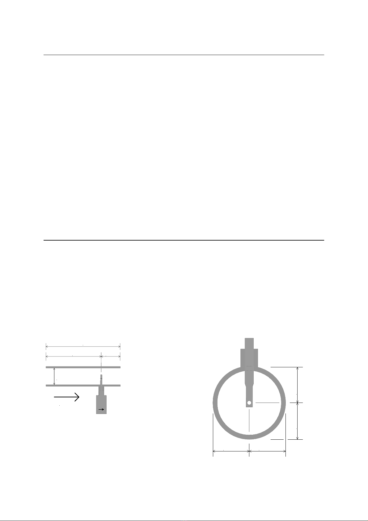
Measuring ranges depending from the inner diameter of the pipe
MEASURING RANGES HIGH SPEED
The sensor VA 400 - high speed version with or without display, has a maximum measuring
range of 224.0 m/sec. The flow rate is programmed to:
Inner diameter: 53.1 mm
This corresponds with an analogue output 4… 20 mA of
0… 1450.06 m³/h 0… 24.17 m³/min 0… 24167.64 l/min 0…402.79 l/sec 0… 224.0 m/sec.
In case of the version with display the inner diameter 25.00 has to be set first if the sensor is used in
other pipes, e. g. 1", 25 mm.
The analogue output for 1" can be taken from the table below: 4… 20 mA =
0… 295.30 m³/h 0... 4.92 m³/min 0… 4921.62 l/min 0… 82.03 l/sec 0… 224.0 m/sec.
In case of the version with display please adjust the respective inner diameter (see page 21).
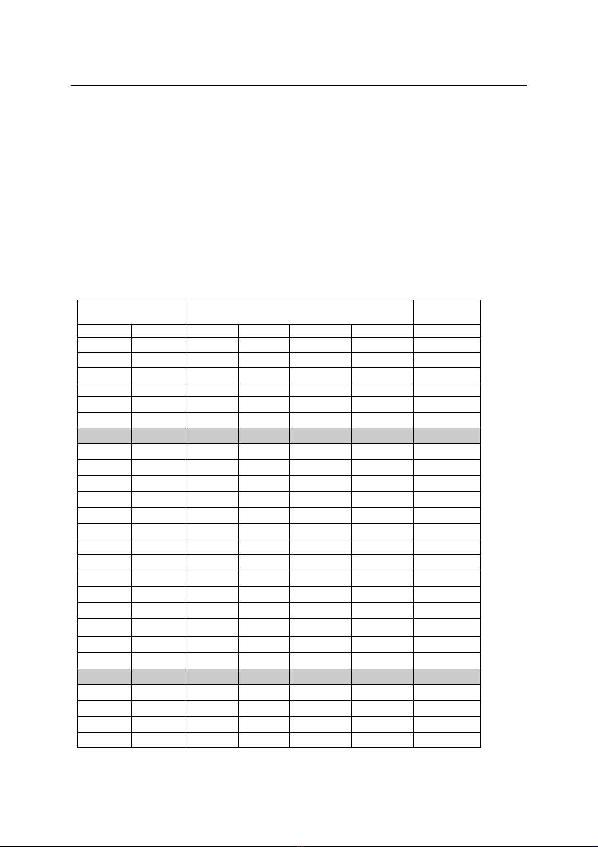
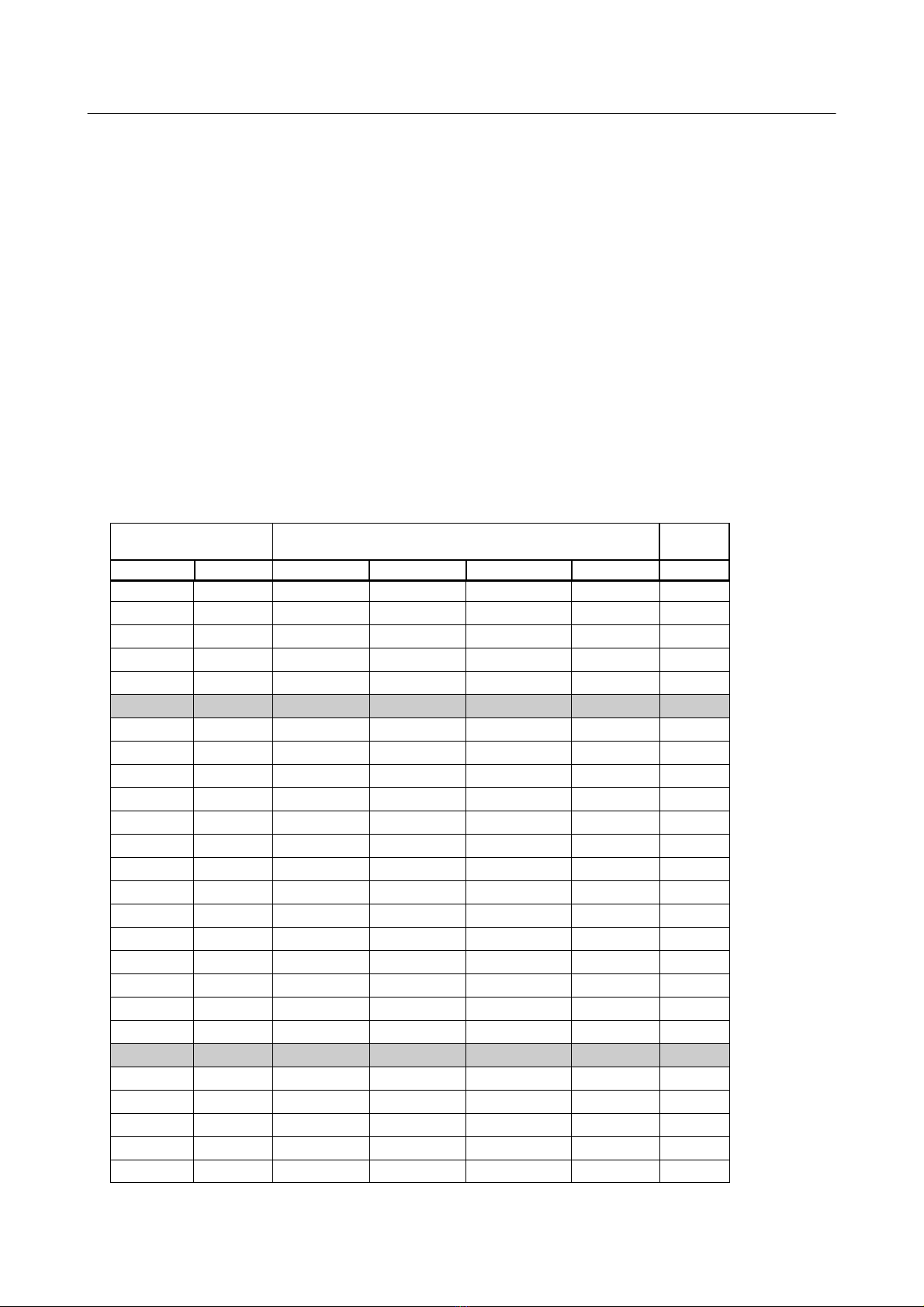
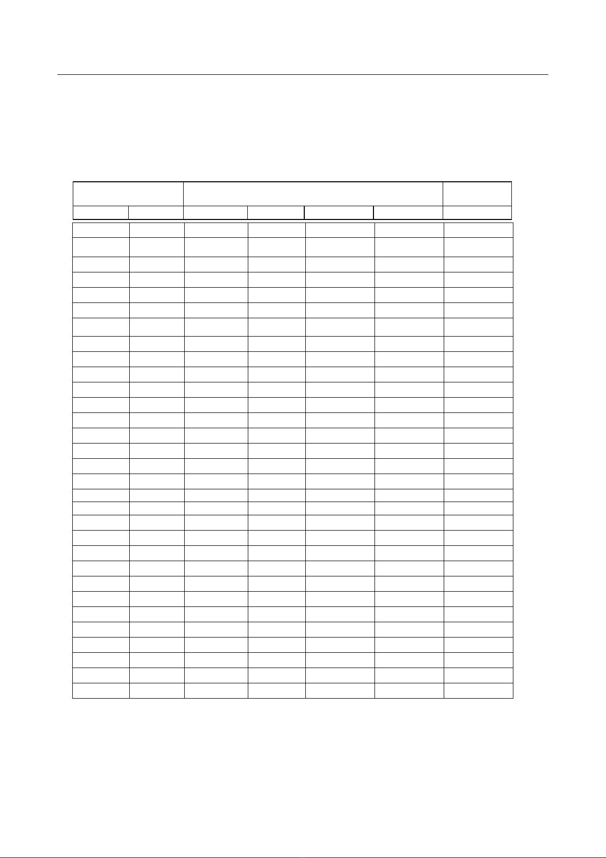
Inner diameter
of the pipe Flow
(final value of measuring range) max.
Inch mm m³/h m³/min l/min l/s m/s
1/4" 6.0 11.40 0.19 190.00 3.17 224.0
10.0 36.42 0.61 606.96 10.12 224.0
15.0 94.05 1.57 1567.53 26.13 224.0
1/2" 16.1 110.16 1.84 1835.96 30.60 224.0
3/4" 21.7 215.33 3.59 3588.77 59.81 224.0
1" 25.0 295.30 4.92 4921.62 82.03 224.0
26.0 321.11 5.35 5351.77 89.20 224.0
27.3 356.85 5.95 5947.52 99.13 224.0
28.5 391.48 6.52 6524.74 108.75 224.0
30.0 437.20 7.29 7286.64 121.44 224.0
1 1/4" 32.8 528.75 8.81 8812.49 146.87 224.0
36.0 643.52 10.73 10725.32 178.76 224.0
36.3 655.12 10.92 10918.73 181.98 224.0
1 1/2" 39.3 774.73 12.91 12912.18 215.20 224.0
40.0 803.59 13.39 13393.14 223.22 224.0
41.8 881.96 14.70 14699.41 244.99 224.0
43.1 941.21 15.69 15686.78 261.45 224.0
45.8 1068.14 17.80 17802.30 296.71 224.0
2" 50.0 1282.52 21.38 21375.40 356.26 224.0
51.2 1346.48 22.44 22441.40 374.02 224.0
53.1 1450.06 24.17 24167.64 402.79 224.0
54.5 1529.41 25.49 25490.17 424.84 224.0
57.5 1712.89 28.55 28548.16 475.80 224.0
60.0 1869.63 31.16 31160.58 519.34 224.0
64.2 2148.38 35.81 35806.27 596.77 224.0
Referred to DIN 1945/ISO 1217 (20 °C, 1000 mbar) and compressed air