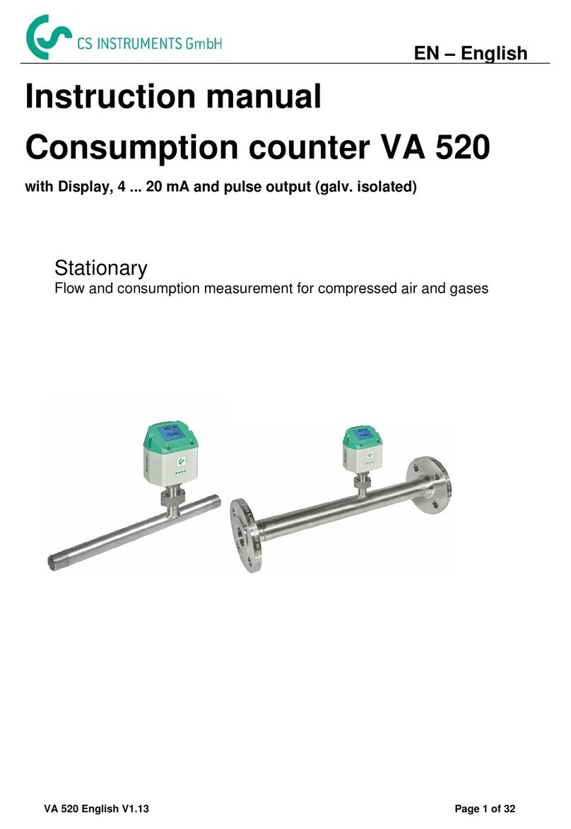
CS Instruments VA 520 User manual

VA 520 English V1.06 Page 1 of 30
EN –English
Instruction manual
Consumption counter VA 520
with Display, 4 ... 20 mA and pulse output (galv. isolated)
Stationary
Flow and consumption measurement for compressed air and gases

VA 520 English V1.06 Page 2 of 30
I. Foreword
Dear customer,
thank you very much for deciding in favour of the VA 520. Please read this
installation and operation manual carefully before mounting and initiating the device
and follow our advice. A riskless operation and a correct functioning of the
VA 520 are only guaranteed in case of careful observation of the described
instructions and notes
Sales Office South / Geschäftsstelle Süd
Zindelsteiner Str. 15
D-78052 VS-Tannheim
Tel.: +49 (0) 7705 978 99 0
Fax: +49 (0) 7705 978 99 20
Mail: [email protected]
Web: http://www.cs-instruments.com
Sales Office North / Geschäftsstelle Nord
Am Oxer 28c
D-24955 Harrislee
Tel.: +49 (0) 461 700 20 25
Fax: +49 (0) 461 700 20 26
Web: http://www.cs-instruments.com

VA 520 English V1.06 Page 3 of 30
II. Table of Contents
I. Foreword ....................................................................................................................... 2
II. Table of Contents ...................................................................................................... 3
1Safety instructions........................................................................................................ 5
2Instruments description ............................................................................................... 6
3Technical data............................................................................................................... 7
4Installation Description ................................................................................................ 8
4.1 Displayhead Position............................................................................................................. 9
5Flow measuring ranges...............................................................................................10
5.1 Flow air.................................................................................................................................. 10
5.2 Flow for different gases....................................................................................................... 10
6Dimensions ..................................................................................................................11
6.1 With measurement section and screw-in thread.............................................................. 11
6.2 With measurement section and flange (Material stainless steel 1.4404):...................... 12
7Electrical wiring / Displayhead position.....................................................................13
7.1 Electrical wiring.................................................................................................................... 13
8Operation......................................................................................................................14
8.1 Initialization .......................................................................................................................... 14
8.2 Main menu ............................................................................................................................ 15
8.3 Settings................................................................................................................................. 15
8.3.1 Sensor Setup................................................................................................................... 16
8.3.1.1 Input / change tube diameter.................................................................................... 16
8.3.1.2 Input / change consumption counter........................................................................ 17
8.3.1.3 Definition of the units for flow, velocity, temperature and pressure ......................... 17
8.3.1.4 Definition of the reference conditions....................................................................... 18
8.3.1.5 Setting of Zeropoint and Low-flow cut off................................................................. 19
8.3.2 Modbus Setup.................................................................................................................. 20
8.3.2.1 Modbus Settings (2001…2005)............................................................................. 21
8.3.2.2 Values Register (1001 …1500) ................................................................................ 21
8.3.3 Pulse /Alarm..................................................................................................................... 23
8.3.3.1 Pulse output.............................................................................................................. 23
8.3.4 User Setup....................................................................................................................... 24
8.3.5 Advanced......................................................................................................................... 24
8.3.6 4 -20mA ........................................................................................................................... 25
8.3.7 VA 520 Info...................................................................................................................... 27

Inhaltsverzeichnis
VA 520 English V1.06 Page 4 of 30
9Maintenance.................................................................................................................28
10 Cleaning of the sensor head....................................................................................28
11 Re-Calibration...........................................................................................................28
12 Spare parts and repair..............................................................................................28
13 Calibration.................................................................................................................28
14 Warranty....................................................................................................................29

VA 520 English V1.06 Page 5 of 30
1Safety instructions
Please read carefully before starting the device!
Warning: Do not exceed the pressure range of 16 bar!
Observe the measuring range of the sensor!
Always observe the direction of flow when positioning the sensor!
The screwed fixture must be pressure tight.
It is absolutely necessary to avoid condensation on the sensor element or water drops in the
measuring air as they may cause faulty measuring results.
The manufacturer cannot be held liable for any damage which occurs as a result of non-
observance or non-compliance with these instructions. Should the device be tampered with
in any manner other than a procedure which is described and specified in the manual, the
warranty is cancelled and the manufacturer is exempt from liability.
The device is destined exclusively for the described application.
We offer no guarantee for the suitability for any other purpose and are not liable for errors
which may have slipped into this operation manual. We are also not liable for consequential
damage resulting from the delivery, capability or use of this device.
We offer you to take back the instruments of the instruments family VA 520 which you would
like to dispose of.
Qualified employees from the measurement and control technology branch should only carry
out adjustments and calibrations.
The consumption sensor VA 520 works according to the calorimetric measuring procedure.
Flammable gases
If this consumption sensor is used for measurement of flammable gases (e. g. natural gas
and so on) we expressly would like to point out that the sensor has no DVGW admission,
however, it can be used for measurements in natural gas. A DVGW admission is not
mandatory.
The consumption sensor corresponds with the current state of technology and basically it can be used
in any flammable and non-flammable gases.
If the sensor is used e.g. in the medium natural gas, the sensor will be adjusted for natural
gas. The calibration protocol (inspection certificate) will be included in the scope of delivery.
The area outside the pipeline (ambient area of the sensor) must not be an explosive area.
The installation has to be carried out by authorized professionals.

VA 520 English V1.06 Page 6 of 30
2Instruments description
The VA 520 is a compact consumption counter for compressed air and gases.
Special features:
- Optimum accuracy due to compact design
- Integrated in- and outlet section
- Less flow due to measuring section
- Integrated Display, Units free selectable. m³/h, m³/min, l/min, l/s, kg/h, kg/min, kg/s, cfm
- Modbus RTU (RS485) Interface
- Analogue output 4..20mA
- Pulse output galv. isolated.
-
CS Instruments Service Software
- Analogue output 4...20 mA scalable
- Selection of gas type (Air, Nitrogen, Argon, Nitrous oxide, CO2, Oxygen, Natural gas)
- Read out Service data
- Sensor diagnoses

VA 520 English V1.06 Page 7 of 30
3Technical data
Measurement: Flow and consumption
Standard settings ex works:
DIN 1945, ISO 1217 at 20°C and 1000 mbar
Selectable Units m³/h (Standard settings ex works)
m³/min, l/min, l/s, ft/min, cfm, m/s, kg/h, kg/min, kg/s
Measuring principle: calorimetric measurement
Sensor: Pt45, Pt1000
Measuring medium: Air, gases
Operating temperature: -30 ... 80°C
Operating pressure: up to 16 bar, special version PN 40 (40 bar)
Power supply: 18 to 36 VDC
Power consumption: max. 5W
Digital output: RS 485 (Modbus RTU)
Analog output: 4...20 mA (see table below),
max. burden < 500 Ohm
Description
Analogue output
VA 520 with integrated 1/4" meas. section
4… 20 mA =
0...90 l/min
VA 520 with integrated 1/2" meas. section
4… 20 mA =
0...90 m³/h
VA 520 with integrated 3/4" meas. section
4… 20 mA =
0...170 m³/h
VA 520 with integrated 1" meas. section
4… 20 mA =
0...290 m³/h
VA 520 with integrated 1 1/4" meas. section
4… 20 mA =
0...530 m³/h
VA 520 with integrated 1 1/2" meas. section
4… 20 mA =
0...730 m³/h
VA 520 with integrated 2" meas. section
4… 20 mA =
0…1195m³/h
VA 520 with integrated 2 1/2" meas. section
4… 20 mA =
0…2185m³/h
VA 520 with integrated 3" meas. section
4… 20 mA =
0…2910m³/h
Pulse output: pulse output potential free (dry contact)
passive: max. 48Vdc, 500mA
1 pulse pro m³ resp. pro l, Valency
adjustable with the display keys
Accuracy: ± 1,5 % m.v., ± 0,3 % f. s.*
Display: TFT 1.8 Resolution 220 x 176
Mounting thread: R 1/4", R1/2", R3/4", R1", R 1 1/4" R1 1/2", R 2” DIN EN
10226 (ISO 7-1)
Material: Stainless steel 1.4301 / 1.4404
Version with flange DIN EN 1092-1: Stainless steel 1.4404
‘* m.v. = measured values
f.s. = full scale

VA 520 English V1.06 Page 8 of 30
4Installation Description
The following table shows the required inlet sections depending on the existing disturbance / flow
disturbance.
Table of additionally required inlet sections
Flow obstruction in front of the
measuring section
Minimum length inlet
section (L1)
Minimum length
outlet section (L2)
Slight curve
(bend < 90°)
12 x D
5 x D
Reduction
(pipe narrows towards the meas. section)
15 x D
5 x D
Expansion
(pipe expands towards the meas. section)
15 x D
5 x D
90° bend
or T-piece
15 x D
5 x D
2 bends á 90°
on one level
20 x D
5 x D
2 bends á 90°
3-dimensional change of direction
35 x D
5 x D
Shut-off valve
45 x D
5 x D
15 x D 5 x D
15 x D 5 x D15 x D
15 x D 5 x D
20 x D 5 x D
35 x D 5 x D
5 x D45 x D
The respective minimum values required are indicated here. If it is not possible to observe the
stipulated equalising sections, considerable deviations in the measuring results must be expected.
Attention:
The measuring sections of VA 520 consumption counters with 1 1/2" and 2" measuring section
have reduced inlet and outlet sections. Please take into consideration the recommended inlet and
outlet sections. Dimension please see page 9 and 10.

VA 520 English V1.06 Page 9 of 30
4.1 Displayhead Position
The Position of the Displayhead is twistable by 180 e.g. in
case of reverse flow direction.
For this purpose the 6 fastening screws are to be released
and the displayhead rotated 180°.
Caution:
It must be ensured that the connection plugs are still plugged
and the gasket is installed correctly.
Fastening screws

VA 520 English V1.06 Page 10 of 30
5Flow measuring ranges
5.1 Flow air
Pipe size
Inner pipe
Ø
Pipe size
VA 520
Consumption
Inch
mm
Meas. ranges from … to
Standard setting
1/4“
8,5
DN 8
0,8…90 l/min
l
1/2“
16,1
DN 15
0,2…90 m³/h
m³
3/4“
21,7
DN 20
0,3...170 m³/h
m³
1“
27,3
DN 25
0,5...290 m³/h
m³
1¼“
36,8
DN 32
0,7…530m³/h
m³
1 ½"
41,8
DN 40
1,0…730 m³/h
m³
2“
53,1
DN 50
2,0...1195 m³/h
m³
2 ½"
71,1
DN 65
4,0…2185 m³/h
m³
3“
81,9
DN 80
7,0…2910 m³/h
m³
Reference DIN 1945/ ISO 1217: 1000mbar /20°C; Air
5.2 Flow for different gases
1/4"
1/2"
3/4"
1"
1 ¼"
1 ½"
2"
2 ½"
3"
Analog
output
20mA
Analog
output
20mA
Analog
output
20mA
Analog
output
20mA
Analog
output
20mA
Analog
output
20mA
Analog
output
20mA
Analog
output
20mA
Analog
output
20mA
l/min
[m³/h]
[m³/h]
[m³/h]
[m³/h]
[m³/h]
[m³/h]
[m³/h]
[m³/h]
Reference DIN1945/ ISO 1217: 20°C, 1000 mbar (Reference during calibration)
Air
90
90
170
290
530
730
1195
2185
2910
Adjustment to DIN 1343: 0°C, 1013,25 mbar
Air
80
20
160
270
490
670
1100
2010
2675
Argon
Ar
140
140
275
460
830
1140
1870
3415
4555
Carbon dioxide
CO2
85
90
175
290
525
720
1185
2160
2880
Nitrogen
N2
80
80
155
260
470
650
1060
1940
2590
Oxygen
O2
85
85
165
280
505
695
1140
2080
2775
Nitrous oxide
N2O
85
85
170
285
520
715
1170
2140
2855
Natural gas
NG
50
50
105
170
310
430
705
1290
1720
Other gases on request
Please note:
The consumption sensor corresponds with the current state of technology and basically it can be used
in any flammable and non-flammable gases.
If this consumption sensor is used for measurement of flammable gases (e.g. natural gas and so on)
we expressly would like to point out that the sensor has no DVGW admission, however, it can be used
for measurements in natural gas. A DVGW admission is not mandatory.
The area outside the pipeline (ambient area of the sensor) must not be an explosive area.

VA 520 English V1.06 Page 11 of 30
6Dimensions
6.1 With measurement section and screw-in thread
Pipe size
AD / ID
(mm)
L
(mm)
L1
(mm)
H
(mm)
H1
(mm)
R
A
(mm)
VA 520 1/4"
DN 8
13,7 / 8,5
194
137
176,6
166,3
R 1/4"
15
VA 520 1/2“
DN 15
21,3 / 16,1
300
210
177,0
166,3
R 1/2“
20
VA 520 3/4“
DN 20
26,9 / 21,7
475
275
179,8
166,3
R 3/4“
20
VA 520 1“
DN 25
33,7 / 27,3
475
275
183,2
166,3
R 1“
25
VA 520 1 1/4"
DN 32
42,4 / 36,0
475
275
187,5
166,3
R 1 1/4"
25
VA 520 1 1/2“
DN 40
48,3 / 41,9
475
275
190,5
166,3
R 1 1/2“
25
VA 520 2“
DN 50
60,3 / 53,1
475
275
196,5
166,3
R 2“
30
Order no.
stainless
steel
1.4404
Order no.
stainless
steel
1.4301
Description
Analogue output
0695 1520
0695 0520
VA 520 with integrated 1/4" meas. section
4… 20 mA =
0...90 l/min
0695 1521
0695 0521
VA 520 with integrated 1/2" meas. section
4… 20 mA =
0...90 m³/h
0695 1522
0695 0522
VA 520 with integrated 3/4" meas. section
4… 20 mA =
0...170 m³/h
0695 1523
0695 0523
VA 520 with integrated 1" meas. section
4… 20 mA =
0...290 m³/h
0695 1526
0695 0526
VA 520 with integrated 1 1/4" meas. section
4… 20 mA =
0...530 m³/h
0695 1524
0695 0524
VA 520 with integrated 1 1/2" meas. section
4… 20 mA =
0...730 m³/h
0695 1525
0695 0525
VA 520 with integrated 2" meas. section
4… 20 mA =
0…1195m³/h

VA 520 English V1.06 Page 12 of 30
6.2 With measurement section and flange (Material stainless steel 1.4404):
Flange DIN EN 1092-1
Pipe size
AD/ID
(mm)
L
(mm)
L1
(mm)
H
(mm)
H1
(mm)
Ø D
in mm
Ø K
in mm
nxØL
in mm
VA 520 1/2“
DN 15
21,3 / 16,1
300
210
213,8
166,3
95
65
4 x 14
VA 520 3/4“
DN 20
26,9 / 21,7
475
275
218,8
166,3
105
75
4 x 14
VA 520 1“
DN 25
33,7 / 27,3
475
275
223,8
166,3
115
85
4 x 14
VA 520 1 1/4"
DN 32
42,4 / 36,0
475
275
263,3
166,3
140
100
4 x 18
VA 520 1 1/2“
DN 40
48,3 / 41,9
475
275
2 40,7
166,3
150
110
4 x 18
VA 520 2“
DN 50
60,3 / 53,1
475
275
248,2
166,3
165
125
4 x 18
Order-No.
Description
Analogue output
0695 2521
VA 520 with integrated 1/2" meas. section with weld neck flange
4… 20 mA =
0...90 m³/h
0695 2522
VA 520 with integrated 3/4" meas. section with weld neck flange
4… 20 mA =
0...170 m³/h
0695 2523
VA 520 with integrated 1" meas. section with weld neck flange
4… 20 mA =
0...290 m³/h
0695 2526
VA 520 with integrated 1 1/4" meas. section with weld neck flange
4… 20 mA =
0...530 m³/h
0695 2524
VA 520 with integrated 1 1/2" meas. section with weld neck flange
4… 20 mA =
0...730 m³/h
0695 2525
VA 520 with integrated 2" meas. section with weld neck flange
4… 20 mA =
0…1195m³/h

VA 520 English V1.06 Page 13 of 30
7Electrical wiring
7.1 Electrical wiring
Attention: Not required connections NC must not be connected to a voltage and/or to
protection earth. Cut and insulate cables.
Pin 1
Pin 2
Pin 3
Pin 4
Pin 5
Connector plug A
+VB
RS 485 (A)
-VB
RS 485 (B)
I+
4..20 mA
Colours connection cables
0553 0104 (5 m)
0553.0105 (10 m)
brown
white
blue
black
grey
Connector plug B
NC
GND
DIR
Pulse
galv. isolated
Pulse
gavl. isolated
Colours pulse cables
0553 0106 (5 m)
0553.0107 (10 m)
brown
white
blue
black
grey
Legend:
-VB
Negative supply voltage 0 V
Pulse
Pulse for consumption
+VB
Positive supply voltage 12...36 VDC smoothed
NC
Must not be connected to a voltage
and/or to protection earth. Please
cut and isolate cables.
I +
Current signal 4...20 mA –selected measured
signal
RS 485 (A)
Modbus RTU A
RS 485 (B)
Modbus RTU B
If no connection cable/ pulse
cable is ordered the sensor will
be supplied with a M12
connector plug. The user can
connect the supply and signal
cables as indicated in the
connection diagram.
.
M12 Connector plug
View from back side
(terminal side)
Connector plug A (M12 - A-coding) Connector plug B (M12 - A-coding)
3
4
5
1
2
+ VB
- VB
4 … 20mA
+ -
Grau / Grey
Blau / Blue
Weiss / White
Schwarz / Black
Modbus (B)
Modbus (A)
120R
Termination
120R
Braun / Brown
Remark: If the sensor is placed at the end of the Modbus system a termination is required. The sensors
have an internal switchable termination, therefore the 6 fastening screws from the lid are to be
released and set the internal DIP Switch to “On”. It must be ensured that the connection plugs are
still plugged and the gasket is installed correctly, see also chapter 4.5.
Alternatively, a 120R resistor can be installed in the plug between pin 2 and pin 4.
- Connector plug A
- Connector plug B
grau
schwarz

VA 520 English V1.06 Page 14 of 30
8Operation
“Up“ ( ) “Enter“ ( )
The operation of the VA 520 is done by the two capacitive key buttons Up () and Enter ()
8.1 Initialization
After switching on the VA 520, the initialized
screen is displayed followed by the main
menu.

VA 520 English V1.06 Page 15 of 30
8.2 Main menu
HW Version Modbus ID
SW Version Seiten Nr.
Gas /
Statusinfo
Switching to pages 2-5 or back by pressing key „“
8.3 Settings
The settings menu could accessed by pressing the key „OK“.
But the access to the settings menu is password protected.
Selection of a menu item or to change
a value is done with the key „“,a
final move to the chosen menu item or
takeover of the value change needs the
confirmation by pressing the key „OK“
Factory settings for password at the
time of delivery: 0000 (4 times zero).
If required the password could be
changed at Setup–User setup-
Password.
.

VA 520 English V1.06 Page 16 of 30
8.3.1 Sensor Setup
Setup Sensor Setup
53.1 mm
8.3.1.1 Input / change tube diameter
Setup Sensor SetupDiameter
For changes, first select the menu item
with key „“and then confirm it with
“OK“.
In order to change, e.g. the unit, first select
by pressing key „“the field “Units” and
then key “OK”.
Select with the key „“the correct unit and
then confirm selection by pressing 2x „OK“.
Entering / changing the diameter
via button „“, select the respective position
and activate the position with the "OK"
button.
By pressing „“ the position value is
incremented by 1. Complete with "OK" and
activate next number position.
Confirm entry by pressing „OK“.

VA 520 English V1.06 Page 17 of 30
8.3.1.2 Input / change consumption counter
Setup Sensor SetupTotal Counter
Important!
When the counter reach 100000000 m³ the counter will be reset to zero.
8.3.1.3 Definition of the units for flow, velocity, temperature and pressure
Setup Sensor SetupUnits
In order to change, e.g. the unit, first select by
pressing key „“the field “Units” and then
key “OK”.
Select with the key „“the correct unit and
then confirm selection by pressing 2x „OK“.
Entering / changing the consumption counter
via button „“, select the respective position
and activate the position with the "OK"
button.
By pressing „“ the position value is
incremented by 1. Complete with "OK" and
activate next number position.
Confirm entry by pressing „OK“.
To make changes to the unit for the respective
measurement value, first select by pressing
„“ the field of the „measurement value“ and
activate „it with „OK“ .
Selection of the new unit with „“
In case the quantity of units selectable are not
presentable on one page, pleas move to next
page by pressing „<<“ .
Confirm selection by pressing 2x „OK“.
Procedure for all 4 measurement variables is
analogous.

VA 520 English V1.06 Page 18 of 30
8.3.1.4 Definition of the reference conditions
Here can be defined the desired measured media reference conditions for pressure and temperature.
Setup Sensor SetupExt. Setup
Filtertime
Setup Sensor Setup Ext. Setup Ref.Pref
Setup Sensor SetupExt. Setup Setup
Ref.Temp
Setup Sensor SetupExt. Setup
Filtertime
To make changes, first select a menu with
button „“and confirm selection by pressing
„OK“ .
In order to change, e.g. the unit, first select by
pressing key „“the field “Units” and then
key “OK”.
Select with the key „“the correct unit and
then confirm selection by pressing 2x „OK“.
Input / change of the value by selecting the
respective position with button „“and
entering by pressing button „OK“ .
By pressing „“ the position value is
incremented by 1. Complete with "OK" and
activate next number position.
.
Under point "Filtertime" together with the
appropriate "Filter Grade" an attenuation can
be defined.
Input values of 0 -10000 in [ms] are possible.

VA 520 English V1.06 Page 19 of 30
8.3.1.5 Setting of Zeropoint and Low-flow cut off
Setup Sensor SetupZP Adjust
Setup Sensor Setup ZP Adjust ZeroPnt
Setup Sensor Setup ZP Adjust
CutOff
Setup Sensor Setup ZP Adjust t Reset
To make changes, first select a menu with
button „“and confirm selection by pressing
„OK“ .
When, without flow, the installed sensor shows
already a flow value of > 0 m³/h herewith the
zero point of the characteristic could be reset.
For an input / change of the value select with
the button „“the respective number position
and activate it with „OK“.
By pressing „“ the position value is
incremented by 1. Confirm the input with „OK“
and activate next number position.
Leave menu with button „Back“
Menüpunkt mit Taste „“anwählen und
anschließend mit Taste „OK“ auswählen
With the low-flow cut off activated, the flow
below the defined "LowFlow Cut off" value will
be displayed as 0 m³/h and not added to the
consumption counter.
For an input / change of the value select with
the button „“the respective number position
and activate it with „OK“.
By pressing „“ the position value is
incremented by 1. Confirm the input with „OK“
and activate next number position.
Leave menu with button „Back“
By selection of „Reset“ all settings for
„ZeroPnt“ and. „CutOff“ are reset.
Menu item to be select with button „“ and
confirm the reset with „OK“ .
Leave menu with button „Back“

VA 520 English V1.06 Page 20 of 30
8.3.2 Modbus Setup
The Flow sensors VA 520 comes with a Modbus RTU Interface.
Before commissioning the sensor the communication parameters
Modbus ID, Baudrate, Parity und Stop bit
must be set in order to ensure the communication with the Modbus master.
Setup Sensor SetupModbus Setup
Default values out of factory: Modbus ID: 1
Baud rate: 19200
Stopbit: 1
Parity: even
Remark: If the sensor is placed at the end of the Modbus system a termination is required. The sensors
have an internal switchable termination, therefore the 6 fastening screws from the lid are to be
released and set the internal DIP Switch to “On”. It must be ensured that the connection plugs are
still plugged and the gasket is installed correctly, see also chapter 4.5.
Alternatively, a 120R resistor can be installed in the plug between pin 2 and pin 4.
For changes, e.g. the sensor ID,
first select by pressing key „“the field
“ID”and then key “OK”.
Select the desired position by pressing the
">" and select with "OK" button.
Change values by pressing the „“values
takeover by pressing "OK".
Inputs for remaining information is analog.
Saving the changes by pressing "Save",
therefore select it first with key „“and
afterwards confirm it with "OK".
Other manuals for VA 520
2
Table of contents
Other CS Instruments Cash Counter manuals
