manuals.online logo
Brands
  1. Home
  2. •
  3. Brands
  4. •
  5. CSH
  6. •
  7. Ladder
  8. •
  9. CSH QG.830 Series Specification sheet

CSH QG.830 Series Specification sheet

INSTRUCTION MANUAL
for Installing
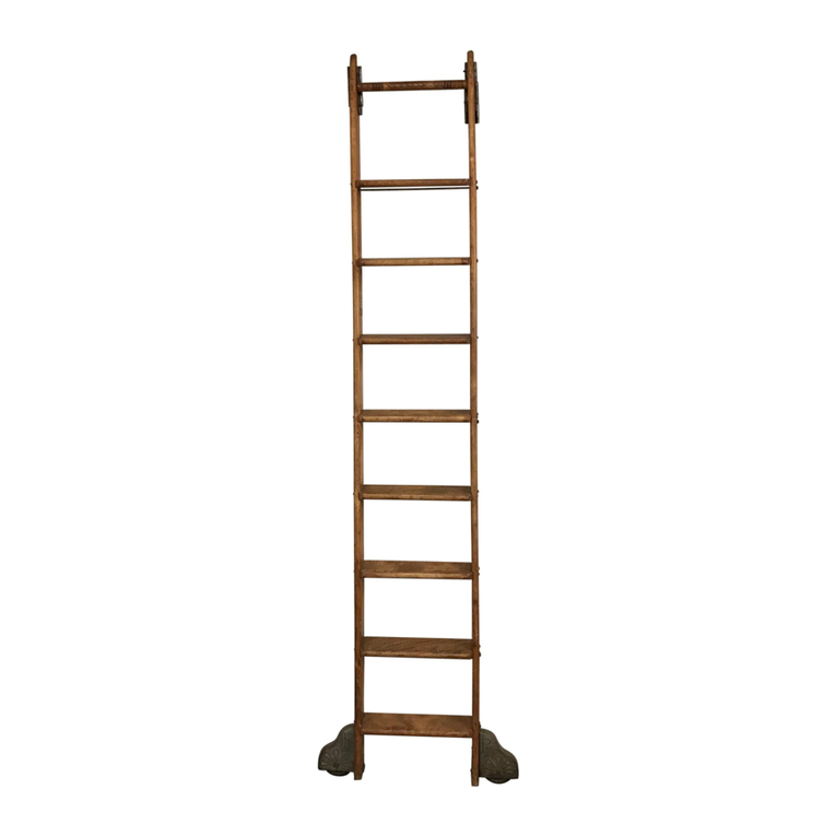
STATIONARY LOFT
LADDER HARDWARE
QG.830 Series
2
Instruction Manual for Installing Stationary Loft Ladder Hardware
Step 1: Ladder Length Calculation
All ladders using the Stationary Loft hardware are
custom, made-to-order ladders.
In order for the ladder to properly move between stored and climbing positions (see figures
1a and 1b), it is critical to order the correct ladder length based on the planned location of
the flat plate.
To calculate the length of ladder required for your specific application:
1. Determine where the Flat Plate portion of the Sliding Upper Guide hardware will be
installed onto the header board below the floor of the loft. The bottom of the flat plate
needs to be a minimum of 3
½
”below the bottom edge of the loft floor.
Note: If the loft floor edge protrudes more than 1” beyond the vertical surface of the header board, the Flat Plate
hardware will need to be installed lower on the header board to allow clearance for the upper sliding hardware
when the ladder goes from the stored to the climbing positions.
2. Scribe a level line on the header board corresponding to the desired position of the
bottom of the Flat Plate. This line will be used when installing the ladder (see Figure 2a
and 2b).
Shown: QG.830.08 Installation Tools Needed:
5mm and 4mm
wrenches
3
3. Measure from the floor surface where the ladder will be standing to the bottom edge
of where the Flat Plate will be installed on the header board (see figure 3).
4. Add 5” to this measurement for the custom ladder length.
Climbing PositionStoring Position
Figure 1a Figure 1b
Figure 2a Figure 2b
3 ½”
Loft Floor
Flat Plate
}
Figure 3
4
3. Using a #9 Vix Bit or a ⅛” drill bit, drill (4) pilot holes into the edge of the ladder (see
figure 5a).
4. Use the supplied #10 x ¾” flat-head screws to secure the sliding upper guides to the
top of the ladder (see figure 5b).
Step 2: Installing the Sliding Upper Guide Hardware to the Ladder
1. On the back edge of both the ladder side rails, measure down ¾” down from the tip of
the ladder and scribe a straight line (see figure 4a and 4b).
2. Align the top edge of the Sliding Upper Guide hardware with the mark on the ladder.
Figure 4a Figure 4b
¾”
Figure 5b
Figure 5a
¾”
Pre-drilling using Vix Bit or 1/8”
drill bit
Securing hardware to ladder using
Phillips-drive flathead screws
5
5. Complete the installation of the Sliding Upper Guide to the ladder using the
¼”x 20
bolts and acorn nuts by following the detailed recommended procedure below.
Using a ¼” drill bit and the holes in the top roller guide as a drill guide, drill a ¼” hole
halfway through the thickness of the ladder slide rail (see figure 6a).
Drill the same hole on the opposite side of the top roller guide, producing a ¼” through hole
in the ladder side rail.
Follow this same procedure for all 4 through holes and complete the assembly by securing
the Sliding Upper Guide with the supplied ¼” x 20 KD bolts and acorn nuts (see figure 6b
and 6c).
Figure 6a
Figure 6c
Figure 6b
6
2. Align the front edge of bottom foot hardware to the scribed line, pushing the bottom
foot hardware tight and flush to the bottom surface of the ladder (see figure 8).
Step 3: Installing the Bottom Foot on the Ladder
1. From the front edge of the ladder side rails, draw a line on the bottom of the rail ¼” in
from the edge (see figure 7).
3. Fasten the bottom foot onto the rail with the
¼”x 20
KD bolts and acorn nuts
following the procedure detailed above (see figure 9a and 9b).
Figure 8
Figure 9b
Figure 7
Figure 9a
7
Step 4: Installing the Ladder onto the Header Board of the Loft
1. Align the ladder in the desired position in front of the opening to the loft.
2. Stand the ladder upright in the vertical stored position (see figure 10) and using
the supplied #10 x
¾
” pan-head screws, install the Flat Plate hardware. Be sure to
position the bottom of the Flat Plate along the scribed line on the header board (see
figure 11a and 11b).
3. The ladder should now be able
to be lifted and pulled out to the
climbing position.
SPECIAL SAFETY NOTE:
Our stationary
loft ladder and hardware will enable
you to get up to the loft area. To
ensure you can get up into and come
back down from the loft safely, please
install handrails firmly attached to
both the railing posts/supports in the
opening which are firmly attached to
the loft floor.
Figure 11b
Figure 10 Figure 11a
8
Measurements for Flat Plate
Stationary Ladder Hardware
Flat Plate Dimensions
2” cc
2⅜” cc
2 ⅞”
overall width
3 ⅜”
overall height
Sliding Upper Guide
Pin to attach Sliding upper
Guide to Flat Plate
Flat Plate
9
More Non-Rolling Options
Rolling Options
DOUBLE HOOK
ROLLING HOOK
TOP SLIDING HOOK
TOP ROLLER SWIVEL
TOP ROLLER
LL.DHGUIDE.08
Starting at $33.00
LL.THGUIDE.08
Starting at $189.00
LL.RHGUIDE.08
Starting at $115.00
LL.SWGUIDE.08
Starting at $195.00
LL.TRGUIDE.08
Starting at $115.00
10
Application Photos of
Rolling Ladders
11
Also available from CSH:
REV. 1.13.20
1170 Wauwatosa Rd.
Cedarburg, WI 53012
cshardware.com
(262) 365-7960
Mini Barn Doors InvisiDoors
Rolling Barn Doors

This manual suits for next models

1

Other CSH Ladder manuals

CSH PUTNAM User manual

CSH

CSH PUTNAM User manual

CSH QUIET GLIDE QG.200 Series User manual

CSH

CSH QUIET GLIDE QG.200 Series User manual

Popular Ladder manuals by other brands
Millennium L-110-SL instruction manual

Millennium

Millennium L-110-SL instruction manual

Loyal Red Giant quick start guide

Loyal

Loyal Red Giant quick start guide

Hailo ProfiStep Duo INSTRUCTION FOR ERECTION AND USE

Hailo

Hailo ProfiStep Duo INSTRUCTION FOR ERECTION AND USE

BENTS KLIK instruction manual

BENTS

BENTS KLIK instruction manual

Batavia Giraffe Air BT-TL005 operating instructions

Batavia

Batavia Giraffe Air BT-TL005 operating instructions

Roto Columbus Quadro 2 installation manual

Roto

Roto Columbus Quadro 2 installation manual

Intex Rondo 126756GN owner's manual

Intex

Intex Rondo 126756GN owner's manual
Centaure 203 1 Series instruction manual

Centaure

Centaure 203 1 Series instruction manual

Next 347453 Assembly instructions

Next

Next 347453 Assembly instructions

Bestway 58331 owner's manual

Bestway

Bestway 58331 owner's manual

INNOVAPLAS Lumi-o BILTMOR DECK 5050 manual

INNOVAPLAS

INNOVAPLAS Lumi-o BILTMOR DECK 5050 manual

KTL 24392909 Use and maintenance handbook

KTL

KTL 24392909 Use and maintenance handbook

Batavia BT-WSL001 instructions

Batavia

Batavia BT-WSL001 instructions

habitat et jardin 91 cm Assembly instructions

habitat et jardin

habitat et jardin 91 cm Assembly instructions

BPS Big Red Foot user guide

BPS

BPS Big Red Foot user guide

POP UP ALPHA DECK Assembly instructions

POP UP

POP UP ALPHA DECK Assembly instructions

HSS Hire 80860 Operating & safety guide

HSS Hire

HSS Hire 80860 Operating & safety guide

POP UP X PRO instructions

POP UP

POP UP X PRO instructions

manuals.online logo
manuals.online logoBrands
  • About & Mission
  • Contact us
  • Privacy Policy
  • Terms and Conditions

Copyright 2025 Manuals.Online. All Rights Reserved.