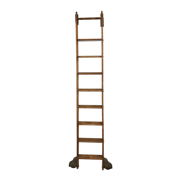
CSH QUIET GLIDE QG.200 Series User manual

QUIET GLIDE ROLLING
LADDER INSTRUCTION
MANUAL
QG.200-300-500-700 Series Hardware

•7" clearance is required above the track's centerline when the ladder is in the storage position
(to avoid contacting ceiling or crown molding), and at least 3" is needed when the ladder is
fully angled for climbing. (Figure 1a-b)
GENERAL INSTALLATION/SPECIFICATION GUIDE
For QG.200, 500, 700 Series Hardware Kits
Step 1: Track Installation Special Application Notes/Cautions:
2
Figure 1a Figure 1b
If NOT using a Splice Kit to connect multiple tracks or installing
End Caps, skip to page 4 for Track Installation.
•Do not mount track brackets directly onto a
drywall surface, even if there is solid wood behind.
Track brackets will eventually crush the drywall,
potentially causing the track system to fail. Track
brackets need to be installed directly onto a solid
wood surface.
•If installing a Standard Double Roller or Swivel
Roller (200 or 700 Series), ladder will need to be
placed onto the track before fastening to wall
and adding End Caps.

3
•Slide all the brackets onto the track (brackets should be no more than 32" apart).
•Install the end caps to the rail.
•
Using a ¼”-20 tapping tool, tap the ends of the track (see Figure 3b).
•
Secure the end cap to the track using the supplied ¼”-20 KD bolt and a 4mm
Allen wrench (see Figure 3c). End result is Figure 3d.
Figure 3a Figure 3c
Figure 3b Figure 3d
Figure 1a
Figure 1b
•If installing a Standard Double Roller or Swivel Roller (200 or 700 Series), ladder will need to be
placed onto the track before adding End Caps.
1. To connect track rails using the Quiet Glide Splice Kit (QG.41), follow these steps:
·
Insert half the length of the roll pin into one of the tracks. (Figure 1a).
·
Slide the steel bar halfway into the track and tighten one of the set screws. (Figure 1b).
•
Line up the other track and slide it over the pin and bar, ensuring
a snug connection. (Figures 2a & b).
•
Complete the splice by tightening the remaining set screw.
Figure 2a Figure 2b
Splice and End Cap Installation Special Application Notes/Cautions

4
2. Slide all of the brackets into the
channel in the metal track (if not
done from Splice Kit steps),
approximating the spacing on your
mounting surface. Brackets should
be no more than 32" apart.
(Figure 2a-b)
3.Determine the center track
installation height and mark the
location for the bottom of the
mounting brackets. Hold the metal
track up to the mounting surface-
lining up your brackets with the
planned locations marked. Mark the
center of both the fastener holes.
(Figure 3a-b)
Figure 2a
Figure 3a
Figure 4
4. Pre-drill your marked
locations using 1/8" bit
for soft wood and
13/64" for hard wood.
(Figure 4)
5. Bring your metal
track with brackets to
your mounting surface
and fasten each bracket
to the wood surface with
the included screws.
(Figure 5)
Figure 5
Please note: If installing a Standard Double
Roller or Swivel (200 or 700 Series), ladder
will need to be placed onto the track before
fastening to wall.
6. Use an accurate leveling device to ensure that the
horizontal locations of the bracket and track are properly
aligned. (Figure 6).
Figure 6
Figure 2b
Figure 3b

5
Step 2: Ladder Assembly (if applicable)
Storage:
•Store the ladder in its original packaging in a humidity-controlled
environment until ready to finish/assemble.
•Lay the stored ladder on a dry, level surface, preferably off the floor (do not
lean against wall for any extended period, this can cause bowing/warping of
the ladder).
Surface prep:
•After removing from shipping packaging, allow the ladder parts to
acclimate to the temperature/humidity of the area where the ladder will be
installed. (Acclimation times vary by species and product, a guide is to
acclimate the wood ladders for at least three days. The goal is to reach an
equilibrium between the moisture content of the wood materials and the air
where the product is being installed)
•Sand all wooden parts with a 220-grit sanding pad just prior to finishing.
(This opens the wood pores creating a more uniform and consistent finish
on the ladder)
•Remove all dust from the ladder prior to finishing.
•It is highly recommended that a high-quality top-coat finish is applied to
the raw, stained, or painted wood ladder to protect and preserve the beauty
of the wood.
Ladder Assembly:
Critical note: A flat, level surface is required. Use 3/4"
plywood spacers under the ladder sides. (See Step 4 below):
1. Lay out the parts to be assembled on the table
(Figure 1)
2. Install the nut caps for the truss rods, use a rubber
mallet if necessary (Figure 2)
3. Install the truss rods loosely into the nut caps using a
5mm Allen wrench, allowing room to slide the steps
into the dados
(detailed in Step 5). For ladders with top
turned rungs, install by gluing the top turned rung in
the side rails (Figure 3-4).
4. Slide 2 plywood spacers under the ladder side rails
(Figure 5-6 below). (Only use 2 spacers for this
operation, additional spacers can result in uneven
side rails)
Figure 1
Figure 2
Figure 3Figure 4

6
5. Slide the steps into the dados, verifying
that the compound miter is lined up in the proper
orientation with the dado. (Figure 7-8). Confirm
that the ladder side rails are all lying flat in contact
with the spacers and the bottom of the ladder side
rails are even with each other and perpendicular to
the sides.
6. Begin tightening the truss rods. (Do not tighten
securely at this time, need to be able to adjust the
height of the steps to align with the dados while
fastening with the supplied screws).(Figure 9-10)
Truss rods should be spaced evenly between the
ladder side rails. The amount of exposed threads
on the truss rods, as viewed on the inside, should
be relatively even.
Figure 5 Figure 6
Figure 7 Figure 8Figure 9 Figure 10
Figure 11 Figure 12
Figure 7 Figure 8
7. Align the compound miter of the step to
the dado. Begin fastening, pushing the side
rail down in tight contact with the plywood
spacers (Figure 11). Completely fasten
each step (both sides) before moving onto
the next step. (Figure 12)

7
8. When all the steps have been
installed, tighten the truss rods
completely. (Figure 13) If assembled
properly, the ladder side rails will be in
tight contact with the plywood spacers
(all 4 contact points). There will also be
a slight, even gap between the table and
the edge of the steps. (Figure 14)
9. For ladders with top turned rungs, clamp the ladder side rails
together and secure the top turned rung with a mechanical
fastener. (Figure 15). Acceptable fasteners:
o18-gauge brad nail, 1-1/2” long, or
o1-1/2” finish nail (4d), need to predrill using a 1/16” drill
bit.
Figure 13Figure 14
Figure 15
Step 3 Ladder Hardware Installation
Upper Hardware Assembly
1. Align the Upper Hardware Assembly on the beveled portion of the ladder by measuring down
1-1/2” from the tip of the ladder (Figure 16) (the top turned rung will be centered between the bolt
holes on the side of the hardware)
2. Using a Vix bit or similar self-centering drill guide, drill a pilot hole into the edge of the ladder for
the (2) #10 x ¾” flat-head, Phillips-drive screws. Secure each Upper Hardware Assembly to the
top of the ladder (Figure 17-18)
Figure 16 Figure 17Figure 18

8
3. Using a ¼” drill bit, drill the holes for the ¼-20 KD bolts on the sides of the ladder (Figure 19-21)
Recommended procedure for this:
•Using the holes in the top roller guide as a drill guide, drill a ¼” hole half way through the
thickness of the ladder slide rail.
•Drill the same hole on the opposite side of the top roller guide, producing a ¼” through
hole in the ladder side rail.
•Follow this same procedure for all 4 through holes and complete the assembly by securing
the top roller guide with the supplied ¼-20 KD bolts and acorn nuts.
Bottom Hardware Assembly
1. Place the bottom roller housing onto the bottom of the ladder using the “U” bracket portion of the
housing. Verify that the bracket is flush with the bottom of the ladder.
(Because of the 12-degree angle of the bottom of the ladder this will align the housing diagonally
across the ladder side rail).
Figure 19Figure 20 Figure 21
2. Mark the location of the “U” bracket
on the bottom of the ladder, approximately
1-1/2” from the front edge of the
ladder (Figure 22). At the same time
mark on the side of the ladder the
location of the top mounting hole of
the bottom roller housing. Measure
these marks and transfer these
measurements to the other ladder side
rail so that the hardware will mount
identically on both ladder side rails.
3. Using a ¼” drill bit, drill a through
hole in the ladder side rail for the ¼-20
KD bolt (Figure 23)
4. Predrill the ladder side rail for the #10
x ¾” screw using a 1/8” drill bit. (This is
critical step to help avoid splitting the
wood, which can lead to failure of the
ladder when weight is applied)
5. Install both the bottom roller guides
using the included screws and KB bolts
and acorn nuts.
Figure 22Figure 23

9
Bottom Wheel Locking Adjustment
(Breaking Wheels only) (Figure 24-25)
The amount of weight needed to engage the
breaking mechanism on the breaking
bottom wheel assemblies is adjustable, the
unit is preset for approximately 70 lbs.
1. Steps for adjustment (Use a 7/32” Allen
wrench for adjustments)
2. Locate the Allen drive screw in the
bottom of the wheel housing (see blue
box below)
3. To decrease sensitivity (need more
weight to engage breaking mechanism),
turn screw clockwise.
4. To increase sensitivity (need less weight
to engage breaking mechanism), turn
screw counterclockwise.
(Be careful not to loosen too much to
prevent the spring from falling out)
Figure 24Figure 25
Hook your ladder onto the track.
Congratulations on
completing your Quite Glide
Ladder!
Please consider leaving a review on
Google Reviews or cshardware.com!
Any questions? Please call CSH
Customer Service at 262-375-7960
M-F 8:00am-4:30pm CST
or email [email protected]

10
1.
Dimensional Specifications
Top Ladder Hardware
CC 6-1/2”
4”
5-1/2”
5-1/2” 1-3/4”
2-1/8” dia
Top Roller 7/8”
4” CC
5-1/2”
4” 1-3/4”
Rolling Hook
6-1/2”
2-1/2” 2” dia
7/8”
6-1/2”
4” CC
5-1/2”
5-1/2” 1-3/4”
Top Swivel Roller 7/8”
4-13/16”
1-3/16”
4-13/64”
3-5/16” 27/32”
53/64”
DoDouble Hook *
*Designed For Loft Applications
6-1/2”
4” CC
5-1/2”
3-7/8” 1-3/4”
Adjustable Hookdj *7/8”
Bottom Ladder Hardware
8”
5-9/16”
Standard Wheel 1-3/8”
7/8”
8-1/4”
6-1/8”
Standard Brake Wheel 1-3/4”
7/8”
6-1/4”
5-9/16”
Contemporary
Wheel 1-3/8 ”
7/8”
6-1/8”
6-1/8”
Contemporary Brake Wheel
1-3/4”
7/8”
3”
Non - Skid Foot
1-1/4"
Protrusion
2-3/8”
Vertical Rail Brackets
For Roller and Swivel Top Guides
3/4”
1-
23/32” 23/32”
2-1/16”CC
15/16”
2-11/16”
1-7/8”
3/4”1-
For Hook and Rolling Hook Top Guides
7/8”
2”CC 2-5/8”
Protrusion
Horizontal Rail Brackets
For Roller and Swivel Top Guides
7/8”
2-3/8”
7/8”
15/16”
1-3/4”
For Hook and Rolling Hook Top Guides
1”
CC
5/8”
1-7/8”
1”
Center of Rail
Bottom of
Horizontal Bracket
11/16”
1-3/4”

11
47”
7”
45°angle
(approximately)
5” radius
Stock = 1-1/4” x 1-1/4”
with 3/16” radius corners
5/8” radius ends
2- Predrilled holes 3/8”
2-1/8”CC on each end
located 3/4” from end
2-1/8”CC
3/4”
Hand Rail dimensions
* +/- 1"
(10’ ladder)
Approximate Distance from wall (ladder in climbing position)
(8’ ladder)
Rail Height and Distance
for 8’, 9’, 10’ standard ladders
114"*
102"*
(9’ ladder)
92.5"*
8' l8' ladder = 25"adder = 25"
10' ladder = 29"
9' ladder = 27"
Bracket
Splice kit
14 -1/2”
1-3/8”
6”
Bracket
38”
30” Radius
90°
Straight section
of curved rail
3 -7/8”
30” Radius
28-3/4”
Bracket
Bracket
Splice kit
21”
135°
Straight section
of curved rail
Bracket
Splice kit
1-3/8”
17”
Bracket
35-1/2”
16” Radius
9”
90°
Straight section
of curved rail
Curved rail radius dimensions
Hook top Hardware cannot be used with curved rails!
Rail Diameter = 1”

Revised 6.20.23
This manual suits for next models
2
Other CSH Ladder manuals
Popular Ladder manuals by other brands

fakro
fakro LWS-P 22/47 Installation instruction
PMB
PMB Quick Access Erection Manual
Confer Plastics
Confer Plastics ROLLGUARD 7200 Assembly and installation manual
Werner
Werner WH2200 SERIES installation instructions

HSS Hire
HSS Hire Conservatory Roof Access System Operating & safety guide

X-Stand
X-Stand MAX XL Assembly and Safe Use Manual
