habitat et jardin 91 cm User manual

FR
EN
Notice de montage et informations à lire et à conserver.....................................................2
Assembly instructions and information to read and keep....................................................12
ES Instrucciones de montaje e información para leer y .............................................................22
ÉCHELLE DE PISCINE
POUR PISCINES HORS SOL
- Modèles 91 cm / 1.07m / 1.22 m / 1.32m -

- 2 -
Charge maximum : 150 kg
•Le matériel qui n’est pas suffisamment serré peutprovoquer une avarie de l’échelle.
•Respecter scrupuleusement les schémas pour les assemblages vis/rondelle/écrou.
•Aprés assemblage et régulierement lors de l’utilisation vérifier lebon serragedes vis et écrous.
Resserrer les assemblages si nécessaire.
•L’échelle ne peut pas être utilisée à d’autres fins.
Avis : des informations supplémentaires relatives à la sécurité sont moulées dans chaque marche
de l’échelle. Prenez le temps de vous familiariser avec ces informations.
Pour éviter de se coincer ou de se noyer, ne pas nager à travers, sous, ou autour de l’échelle. Ne
pas plonger ni sauter depuis l’échelle - eau peu profonde ! Retirer et sécuriser l’échelle quand la
piscine n’est pas utilisée. Pour limiter les risques de blessure, ne pas laisser les enfants utiliser ce
produit sans être surveillé à chaque instant.
AVERTISSE M ENT
•L’échelle doit être assemblée par un adulte ; faites à attention de ne pas perdre ou endommager
de composants ou de vous blesser au déballage et à l’assemblage, cette échelle peut contenir des
bords tranchants ou pointus quisontunepartienécessaire de la fonction de l’échelle.
•L’échelle doit être placée sur un sol solide, plan et horizontal et l’échelle doit être assemblée
et installée conformément aux instructions du fabricant. Utilisez l’échelle de la piscine comme le
seul moyen d’entrée et de sortiede la piscine.
•Une seule personne peut utiliser l’échelle à la fois.
•Retirez l’échelle lorsque vous quittez la piscine.
• Cette échelle est conçue et fabriquée pour une hauteur de paroi spécifique.
•Pour l’entrée / sortie de la piscine, soyez face à l’échelleà tout moment.
ÉCHEL LE
Hivernage de l’échelle :
• Enlevez l’échelle de la piscine. Nettoyez l’échelle avec de l’eau et du savon neutre.
• Démontez-la soigneusement dans l’ordre inverse à celui de l’installation afin de ne pas l’endommager, la
casser ou la déformer.
• Veillez à ce que toutes les pièces soient parfaitement propres et sèches avant de les ranger.
• Pour le remontage de votre échelle, suivez de nouveau les instructions, conseils et avertissements de
sécurité donnés dans le présent manuel de montage.
Garder les marches de l’échelle propre et sans boue, ce qui pourrait provoquer des glissements.
ENTRETIEN DE L’ÉCHELLE
STOCKAGE ET HIVERNAGE
FR
-2 -

LISTE DES PIÈCES
Vis métaux C
(L55 mm)P5911600450A x2 P5911600450A x2 P5911600450A x2
19
Pied d’échelle P5911512320W x2 P5911512520W x2 P5911514270W x2
20
Rondelle plate en
plastiqueP59PF4490P01 x4 P59PF4490P01 x4 P59PF4490P01 x4
21
Clip Bas d’échelle P59PF4500B01 x2 P59PF4500B01 x2 P59PF4500B01 x2
P5911600450A x2 P5911600450A x2
P5911515270W x2 P5911515270W x2
P59PF4490P01 x4 P59PF4490P01 x4
P59PF4500B01 x2 P59PF4500B01 x2
-3 -
36” (91 cm) 42” (107 cm) 48” (122 cm) 52” (132 cm)
A
B
C
D
A
B
C
D
A
B
C
D
A
B
C
D
A
B
C
D
A
B
C
D
E
A
B
C
D
E
A
B
C
D
E
A/B/C/D
A/B/C/D
A/B/C/D
A/B/C/D
P59116 003 5 0A
P5942M60000A
P5943M60000A
P59231M6000A
P5901512322W
P5901512322C
P5901512322K
P5901512322N
P5901512320W
P5901512320C
P5901512320K
P5901512320N
P5901512323W
P5901512323C
P5901512323K
P5901512323N
P5901512321W
P5901512321C
P5901512321K
P5901512321N
P5911011200W
P5911011200C
P5911011200K
P5911011200N
P59PP3800B01
P59PP3800W05
P59PP38007CN
P59PP38008UN
- -
P59PF0090B01
P59PF0090W05
P59PF00907CN
P59PF00908UN
--
P59PF0070B01
P59PF0070W05
P59PF00707CN
P59PF00708UN
--
P59116 00350A
P5942M60000A
P5943M60000A
P59231M6000A
P5901512522W
P5901512522C
P5901512522K
P5901512522N
P5901512520W
P5901512520C
P5901512520K
P5901512520N
P5901512523W
P5901512523C
P5901512523K
P5901512523N
P5901512521W
P5901512521C
P5901512521K
P5901512521N
P5911011200W
P5911011200C
P5911011200K
P5911011200N
P59PP3800B01
P59PP3800W05
P59PP38007CN
P59PP38008UN
P59PP3800C01
P59PF0090B01
P59PF0090W05
P59PF00907CN
P59PF00908UN
P59PF0090C01
P59PF0070B01
P59PF0070W05
P59PF00707CN
P59PF00708UN
P59PF0070C01
P59116 00350A
P5942M60000A
P5943M60000A
P59231M6000A
P5901514272W
P5901514272C
P5901514272K
P5901514272N
P5901514270W
P5901514270C
P5901514270K
P5901514270N
P5901514273W
P5901514273C
P5901514273K
P5901514273N
P5901514271W
P5901514271C
P5901514271K
P5901514271N
P5911011200W
P5911011200C
P5911011200K
P5911011200N
P59PP3800B01
P59PP3800W05
P59PP38007CN
P59PP38008UN
P59PP3800C01
P59PF0090B01
P59PF0090W05
P59PF00907CN
P59PF00908UN
P59PF0090C01
P59PF0070B01
P59PF0070W05
P59PF00707CN
P59PF00708UN
P59PF0070C01
P59116 00350A
P5942M60000A
P5943M60000A
P59231M6000A
P5901515272W
P5901515272C
P5901515272K
P5901515272N
P5901515270W
P5901515270C
P5901515270K
P5901515270N
P5901515273W
P5901515273C
P5901515273K
P5901515273N
P5901515271W
P5901515271C
P5901515271K
P5901515271N
P5911011200W
P5911011200C
P5911011200K
P5911011200N
P59PP3800B01
P59PP3800W05
P59PP38007CN
P59PP38008UN
P59PP3800C01
P59PF0090B01
P59PF0090W05
P59PF00907CN
P59PF00908UN
P59PF0090C01
P59PF0070B01
P59PF0070W05
P59PF00707CN
P59PF00708UN
P59PF0070C01
1
2
3
4
5
6
7
8
9
q
w
e
M6x35 mm
M6xT1.5
L
R
L
R

N° de pièce Qté. N° de pièce Qté. N° de pièce Qté.
1
Pieds d'échelle P5901512320W x2 P5901512520W x2 P5901514270W x2
2
Poignées d'échelleP5911011200W x2 P5911011200W x2 P5911011200W x2
3
Marches d'échelle P59PF5660B01 x6 P59PF5660B01 x6 P59PF5660B01 x8
4
EmboutP59PF0090B01 x4 P59PF0090B01 x4 P59PF0090B01 x4
5
Cclip de fixation P59PF0070B01 x13 P59PF0070B01 x13 P59PF0070B01 x17
6
Vis métaux A
(L55 mm)P5911600350A x8 P5911600350A x8 P5911600350A x8
7
Rondelle plate (metal) P5942M60000Ax10P5942M60000Ax10 P5942M60000Ax10
8
Rondelle de blocage P5943M60000Ax12 P5943M60000Ax12P5943M60000Ax12
9
Écrous chapeau P59231M6000Ax16 P59231M6000Ax16 P59231M6000Ax16
10
Barre de renfort avec
instruction de sécurité P5942003661W x2 P5942003661W x2 P5942003661W x2
11
Vis métaux
(L00 mm)P5911600400A x8 P5911600400Ax8 P5911600400A x8
Hauteur de pa
ro
91cm 107cm 122cm
N° de pièce Qté. N° de pièce Qté.
P5901515270W x2 P5901515270W x2
P5911011200W x2 P5911011200W x2
P59PF5660B01 x8 P59PF5660B01 x8
P59PF0090B01 x4 P59PF0090B01 x4
P59PF0070B01 x17 P59PF0070B01 x17
P5911600350A x8 P5911600350A x8
P5942M60000Ax10 P5942M60000Ax10
P5943M60000Ax12 P5943M60000Ax12
P59231M6000Ax16 P59231M6000Ax16
P5942003661W x2 P5942003661W x2
P5911600400A x8 P5911600400A x8
o
i
132cm
Tube gris /
marche blanche
132cm
Tube moka / marche
marron
12
Charnière P5992001753W x2 P5992001753W x2 P5992001753W x2
13
Pied Vertical P5961510420W x2 P5961510360W x2 P5961512160W x2
14
Clips Pivotant avec le
Bouton P59PF4461B01 x1 P59PF4461B01 x1 P59PF4461B01 x1
15
Clips Pivotant P59PF4460B01 x1 P59PF4460B01 x1 P59PF4460B01 x1
16
Ecrou hexagonal P59211M6000A x2 P59211M6000A x2 P59211M6000A x2
17
Pied-socle P59A2005204W x1 P59A2005204W x1 P59A2005204W x1
P5992001753W x2 P5992001753W x2
P5961513300W x2 P5961513300W x2
P59PF4461B01 x1 P59PF4461B01 x1
P59PF4460B01 x1 P59PF4460B01 x1
P59211M6000A x2 P59211M6000A x2
P59A2005204W x1 P59A2005204W x1
-4 -
36” (91 cm) 42” (107 cm) 48” (122 cm) 52” (132 cm)
A
B
C
D
A/B/C/D
A
B
C
D
A
B
C
D
A
B
C
D
E
A
B
C
D
E
A
B
C
D
E
A
B
C
D
E
A/B/C/D
A/B/C/D
A
B
C
D
P5911600400A
P59211M6000A
P59116 00 4 5 0A
P59PF4490P01
P5942003661W
P5942003661C
P5942003661K
P5942003661N
P5992001753W
P5992001753C
P5992001753K
P5992001753N
P5961510420W
P5961510420C
P5961510420K
P5961510420N
P59PF4461B01
P59PF4461W05
P59PF44617CN
P59PF44618UN
--
P59PF4460B01
P59PF4460W05
P59PF44607CN
P59PF44608UN
--
P59A2005204W
P59A2005204C
P59A2005204K
P59A2005204N
P59PF4500B01
P59PF4500W05
P59PF45007CN
P59PF45008UN
--
P54360030099
P5436003C099
P5436003000K
P5436003000N
--
P5911600400A
P59211M6000A
P59116 00 4 5 0A
P59PF4490P01
P5942003661W
P5942003661C
P5942003621K
P5942003661N
P5992001753W
P5992001753C
P5992001753K
P5992001753N
P5961510360W
P5961510360C
P5961510360K
P5961510360N
P59PF4461B01
P59PF4461W05
P59PF44617CN
P59PF44618UN
P59PF4461C01
P59PF4460B01
P59PF4460W05
P59PF44607CN
P59PF44608UN
P59PF4460C01
P59A2005204W
P59A2005204C
P59A2005204K
P59A2005204N
P59PF4500B01
P59PF4500W05
P59PF45007CN
P59PF45008UN
P59PF4500C01
P54420030099
P5442003C099
P5442003000K
P5442003000N
P5442003C199
P5911600400A
P59211M6000A
P59116 00 4 5 0A
P59PF4490P01
P5942003661W
P5942003661C
P5942003661K
P5942003661N
P5992001753W
P5992001753C
P5992001753K
P5992001753N
P5961512160W
P5961512160C
P5961512160K
P5961512160N
P59PF4461B01
P59PF4461W05
P59PF44617CN
P59PF44618UN
P59PF4461C01
P59PF4460B01
P59PF4460W05
P59PF44607CN
P59PF44608UN
P59PF4460C01
P59A2005204W
P59A2005204C
P59A2005204K
P59A2005204N
P59PF4500B01
P59PF4500W05
P59PF45007CN
P59PF45008UN
P59PF4500C01
P54480030099
P5448003C099
P5448003000K
P5448003000N
P5448003C199
P5911600400A
P59211M6000A
P59116 00 4 5 0A
P59PF4490P01
P5942003661W
P5942003661C
P5942003661K
P5942003661N
P5992001753W
P5992001753C
P5992001753K
P5992001753N
P5961513300W
P5961513300C
P5961513300K
P5961513300N
P59PF4461B01
P59PF4461W05
P59PF44617CN
P59PF44618UN
P59PF4461C01
P59PF4460B01
P59PF4460W05
P59PF44607CN
P59PF44608UN
P59PF4460C01
P59A2005204W
P59A2005204C
P59A2005204K
P59A2005204N
P59PF4500B01
P59PF4500W05
P59PF45007CN
P59PF45008UN
P59PF4500C01
P54520030099
P5452003C099
P5452003000K
P5452003000N
P5452003C199
r
t
y
u
i
o
p
a
s
d
f
*
M6x45 mm
M6x40 mm

- 5 -
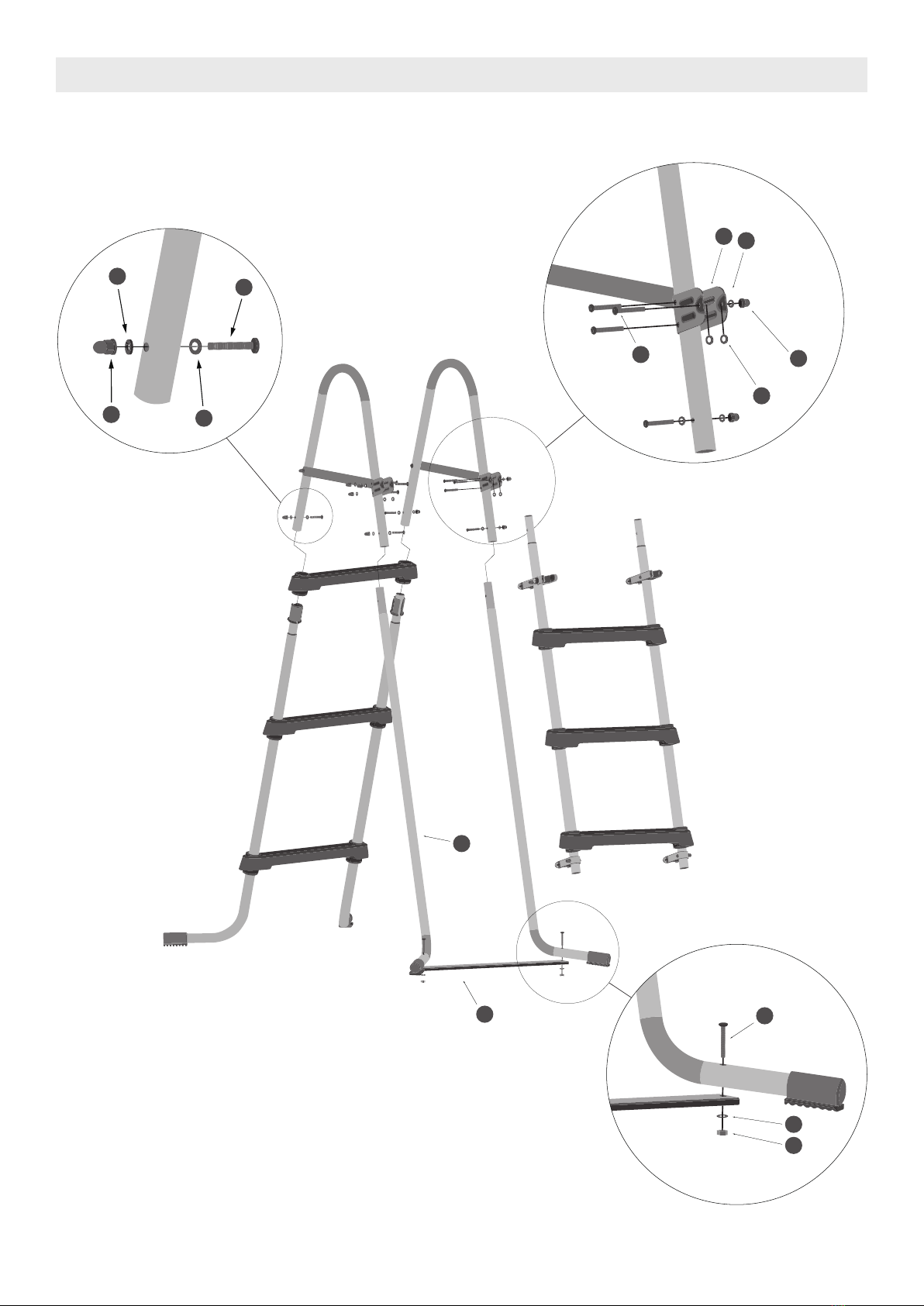
1. Pour monter la poignée de l'échelle (voir Fig. 1), les vis à métaux 11 doivent être installées depuis l'intérieur
de la charnière 12 , puis à travers la poignée d’échelle 2, et à travers la barre de renfort avec instruction de
sécurité 10 vers l'extérieur. Assurez vous que l'étiquette d'avertissement soit orientée vers l'extérieur sur les
deux poignées. Installer la rondelle de blocage 8 et visser l’écrou à chapeau 9 jusqu'à ce que la barre de
renfort soit serrée contre la poignée.
2. Les vis à métaux 6 doivent être installées depuis l'intérieur de la poignée d’échelle 2, et à travers la barre
de renfort. Installer la rondelle plate 7, la rondelle de blocage 8 et visser l’écrou à chapeau 9 jusqu'à ce
que la barre de renfort avec instruction de sécurité 10 se soit serrée contre la poignée d’échelle (Voir Fig. 1).
3. Pour préparer le pied d’échelle (voir Fig. 2), commencer avec le pied "R" (droit) de l’échelle. Ouvrir avec
précaution un clip de fixation 5 sur le coté, juste assez pour passer par dessus le haut du pied de
l’échelle 1, et faites le glisser du haut du pied de l’échelle sur la partie inférieure échancrée comme le
montre la Figure 2. Le clip de fixation devrait être à l'intérieur de la jambe comme le montre la Figure 2.
Répétez le même processus pour le pied "L" (gauche).
4. Glisser une marche 3 sur les deux pieds. Assurez vous que le côté de la marche marquée "R" est bien sur
le pied droit. Faites glisser la marche jusqu’à ce que les bagues pour les marches de l’échelle 5 s’insèrent
dans le dessous de la marche et que les arêtes à l’intérieur de la bague se bloquent à la bonne place. Les
clips de fixation doivent rester dans la partie échancrée du pied de l’échelle pendant que vous appuyez sur
les marches. (Voir Fig 3).
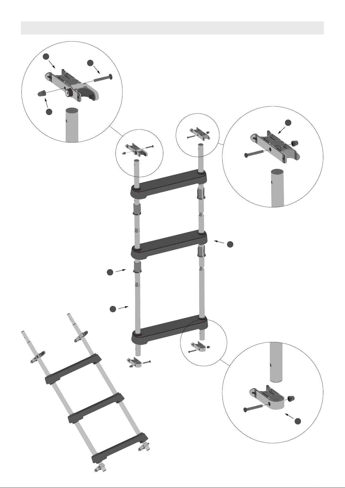
5. Pour préparer l'échelle pivotante (voir Fig. 4), démarrez avec un pied droit 13 . Ouvrir avec précaution le
clip de fixation 5 sur le côté, juste assez pour insérer la partie supérieure du pied droit 13 , et le faire glisser à
partir du haut de la jambe au plus bas de l'article en retrait comme le montre le Figure 4. Le clip de fixation
doit être à l'intérieur de la jambe comme le montre la Figure 4. Répétez le même procédé pour faire l’autre
pied.
6. Glisser une marche 3 à la fois sur le pied. Faites glisser la marche jusqu’à ce que les bagues pour les
marches de l’échelle 5 s’insèrent dans le dessous de la marche et que les arêtes à l’intérieur de la bague se
bloquent à la bonne place. Les clips de fixation doivent rester dans la partie échancrée du pied de l’échelle
pendant que vous appuyez sur les marches. Le clip de fixation doit être à l'intérieur de la jambe comme le
montre la Figure 5.
7. Placer les clips pivotant 14 sur les plus hautes marches du pied comme le montre la Figure 4. Le bouton
doit être tourné vers l'extérieur et la pince avec la serrure doit pointer vers l'avant. Le Clip Pivotant 15 est
installé sur l'autre côté de la jambe droite de l’échelle comme le montre la Figure 4. La petite pince doit
être orientée vers l'avant.
8. La vis à métaux 11 doit être installée à partir de l'intérieur du pied vertical 13 . Enfilez l'écrou à chapeau
9 jusqu'à ce que le pied pivotant se resserre contre le pied de l’échelle. (Voir Fig. 5).
9. Placez le Clip Bas d’échelle 21 au bas de la jambe droite de l’échelle comme le montre la Figure 4. Les
Vis à métaux 11 doivent être installées à partir de l'intérieur des pied Verticaux 13 . Enfilez Ecrou à chapeau
9 jusqu'à ce que les Clip Bas d’échelle se resserrent contre les Pieds Verticaux. (Voir Fig. 4)
10. Mettez les deux pieds de l’échelle dans la position « debout », la base des pieds faisant face à l’extérieur,
comme le montre la Figure 3. Placez les poignées de l’échelle, avec les attaches des poignées à l’extérieur
de l’échelle, en haut de chaque pied de l’échelle.
11. Assurez‐vous que toutes les marches sont maintenant à niveau (parallèles au sol). Si une section est
différente, soulevez les poignées et tournez le pied de l’échelle sur le côté. Réinstallez les poignées et
appuyez bien.
12. De l'intérieur de la poignée de l’échelle 2, insérer les deux vis 6 à travers les rondelles plates 7, puis à
travers la poignée échelle et fixez avec les rondelles de blocage 8 et les écrous 9. (Voir Fig. 6).
INSTRUCTIONS D’ASSEMBLAGE
- 5 -

- 6 -
13. Tenir les pieds gauche et droit 19 en position debout, les pieds vers l'extérieur, comme indiqué dans la
Figure 6.
14. De l'intérieur de la poignée 2, insérer les deux vis 6 à travers les rondelles plates 7, puis à travers la
poignée échelle et fixez avec les rondelles de blocage 8 et les écrous 9 . (Voir Fig. 6) Version 28/09/2015 8.
15. Placer le pied‐socle 17 entre les jambes de l’échelle 19 comme indiqué dans la Figure 6.
16. Du haut des pieds de l’échelle 19 , insérer les deux vis 6 à travers les rondelles plates 7, puis à travers
la poignée de l’échelle et fixez en place avec les écrous hexagonaux 16 comme indiqué dans la Figure 6 .
17. Placer le pied pivotant sur la charnière 12 et le clip sur le pied de l’échelle avec le clips pivotant avec le
bouton 14 et le clips pivotant 15 comme le montre la Figure 6. Insérez une rondelle plate en plastique 20
dans chaque charnière.
18. Insérez les vis à métaux 18 par les rondelles plates en plastique 20 , ensuite par la jambe d'échelle
attachez en place avec l’rondelle de blocage 8 et écrou de Chapeau 9. (Voir Fig. 6).
19. La partie pivotante doit être à l’extérieure de la piscine. S’assurez que les attaches 14 sont bien clipser
sur l’échelle 14 quand l'échelle est en cours d'utilisation. (Voir Fig. 7).
20. Lorsque l'échelle n’est pas utilisée, la partie pivotante doit être accrochées sur la poignée échelle jusqu’à
entendre un «clic» sonore. (Voir Fig. 8).
21. Pour utiliser l'échelle, appuyez sur le bouton du clip pivotant avec le bouton 14 et le pivotez l'échelle
dans la position d'utilisation comme le montre la Figure 7.
- NOTE -
CETTE ÉTAPE EST TRÈS IMPORTANTE CAR ELLE EMPÊCHE LES POIGNÉES DE SE SÉPARER DES
PIEDS – L’ÉCHELLE TOMBERA SI LES VIS NE SONT PAS CORRECTEMENT INSTALLÉES
- 6 -

- 7 -
- ASSEMBLAGE BRAS DE L’ÉCHELLE -
- FIG. 1 -
9
8
7
6
8
9
2
11
10
11
12
- ASSEMBLAGE PIEDS DE L’ÉCHELLE -
3
5
1
4
- FIG. 2 -
- FIG. 3 -
- 7 -

- 8 -
- ASSEMBLAGE PIED PIVOTANT -
14
11
9
5
3
13
21
15
- FIG. 4 -
- FIG. 5 -
- 8 -

- 9 -
- ASSEMBLAGE COMPLET -
8
6
8
9
7
18
12
20
19
17
16
9
6
7
- FIG. 6 -
- 9 -

- 10 -
- ÉCHELLE EN UTILISATION -
- ÉCHELLE INACTIVE -
La partie pivotante est à
l’extérieure de la piscine.
Le Clips Pivotant avec le bouton se verrouillera
automatiquement à la poignée échelle en
position verticale au repos.
Appuyez sur le bouton pour déverrouiller l'échelle.
- FIG. 8 -
- FIG. 7 -
- FIG. 9 -
- 10 -

SERVICE APRÈS-VENTE ET GARANTIES
-11 -
Avant toute demande de pièces détachées, se munir de cette notice pour indiquer le numéro de la pièce
concernée (voir tableau p.3-4)
ATTENTION : Ne pas modifier le produit. Toute modification du produit entraîne la suppression de la
garantie.
La garantie ne couvre pas :
• Les cas de non-respect des conditions d’utilisation, d’entretien, de maintenance et de stockage décrites
dans ce manuel d’instructions,
• Une utilisation anormale du produit,
• Des dommages induits par des chocs reçus par le produit,
• L’usure normale des pièces détachées,
• Undysfonctionnementàlasuited’unemodificationduproduit.
Veuillez soumettre votre plainte au service après-vente suivante par téléphone ou par e-mail.
• FRANCE
33(0) 969360535
• SPAIN
0902848775
•GERMANY
0800 1862132
- PAYS / LOCALISATION DES CENTRES DE SERVICES
Accessible du lundi au vendredi de 9h00 à 18h00
Pour une demande plus rapide, nous vous conseillons de poser votre réclamation
directement sur notre site dédié au SAV : www.polygroupsummerwaves.eu
Nous vous demanderons les éléments suivants :
- Nom
- Adresse
- Email
- Téléphone portable
- Date d'achat + ticket de caisse (ou preuve d'achat)
- 3 Photos format (JPEG,JPG) : 1 prise de loin dans son environnement; 1 de prés; 1
de détails (zoom)

•LADDER WEIGHT LIMIT IS 150 KG
• LOOSE HARDWARE WILL RESULT IN LADDER FAILURE
•The ladder will fail if the Machine Screws, Washers, Lock Washers and Cap Nuts olding
handles to legs are not properly installed
• Check all nuts and bolts regularly o ensure that the ladder stays sturdy
• Ladder Shall not be used or other purpose
NOTICE: Additional Safety Info is molded into each Ladder Step. Please take some time to
become familiar with this info
To prevent entrapment or drowning do not swim through, behind, or around ladder. No diving /
no jumping from ladder - shallow water! To reduce the risk of injury, do not permit children to
use this product unless they are closely supervised at all times.
WARNINGS
•The ladder is to be assembled by an adult; care should be taken in the unpacking and
assembly of the ladder, this ladder may contain accessible potentially hazardous sharp edges
or sharp points that are a necessary part of the function of the ladder.
•The ladder shall be located on a solid base and the ladder shall be installed per the
manufacturer’s instructions. Use the pool ladder as the only means of entering and exiting the
pool.
• One person on the ladder/stair at a time
• Remove the ladder when you leave the pool.
•This ladder is designed and manufactured for a specific pool wall height.
• For entry/exit of pool, face the ladder at all times.
LADDER
Wintering the ladder :
• Remove the ladder from the pool. Clean the ladder with water and neutral soap.
• Carefully disassemble it in reverse order to that of installation so as not to damage, break or deform it.
• Make sure that all parts are perfectly clean and dry before putting them away.
• When reassembling your ladder, follow the instructions, advice and safety warnings given in this assembly
manual again.
Keep ladder steps cleared off and free of mud, which causes slipping
LADDER MAINTENANCE
LADDER STORAGE & WINTERIZING
EN
-12 -

PARTS LIST
-13 -
36” (91 cm) 42” (107 cm) 48” (122 cm) 52” (132 cm)
A
B
C
D
A
B
C
D
A
B
C
D
A
B
C
D
A
B
C
D
A
B
C
D
E
A
B
C
D
E
A
B
C
D
E
A/B/C/D
A/B/C/D
A/B/C/D
A/B/C/D
P59116 00350A
P5942M60000A
P5943M60000A
P59231M6000A
P5901512322W
P5901512322C
P5901512322K
P5901512322N
P5901512320W
P5901512320C
P5901512320K
P5901512320N
P5901512323W
P5901512323C
P5901512323K
P5901512323N
P5901512321W
P5901512321C
P5901512321K
P5901512321N
P5911011200W
P5911011200C
P5911011200K
P5911011200N
P59PP3800B01
P59PP3800W05
P59PP38007CN
P59PP38008UN
- -
P59PF0090B01
P59PF0090W05
P59PF00907CN
P59PF00908UN
--
P59PF0070B01
P59PF0070W05
P59PF00707CN
P59PF00708UN
--
P59116 00350A
P5942M60000A
P5943M60000A
P59231M6000A
P5901512522W
P5901512522C
P5901512522K
P5901512522N
P5901512520W
P5901512520C
P5901512520K
P5901512520N
P5901512523W
P5901512523C
P5901512523K
P5901512523N
P5901512521W
P5901512521C
P5901512521K
P5901512521N
P5911011200W
P5911011200C
P5911011200K
P5911011200N
P59PP3800B01
P59PP3800W05
P59PP38007CN
P59PP38008UN
P59PP3800C01
P59PF0090B01
P59PF0090W05
P59PF00907CN
P59PF00908UN
P59PF0090C01
P59PF0070B01
P59PF0070W05
P59PF00707CN
P59PF00708UN
P59PF0070C01
P59116 00350A
P5942M60000A
P5943M60000A
P59231M6000A
P5901514272W
P5901514272C
P5901514272K
P5901514272N
P5901514270W
P5901514270C
P5901514270K
P5901514270N
P5901514273W
P5901514273C
P5901514273K
P5901514273N
P5901514271W
P5901514271C
P5901514271K
P5901514271N
P5911011200W
P5911011200C
P5911011200K
P5911011200N
P59PP3800B01
P59PP3800W05
P59PP38007CN
P59PP38008UN
P59PP3800C01
P59PF0090B01
P59PF0090W05
P59PF00907CN
P59PF00908UN
P59PF0090C01
P59PF0070B01
P59PF0070W05
P59PF00707CN
P59PF00708UN
P59PF0070C01
P59116 00350A
P5942M60000A
P5943M60000A
P59231M6000A
P5901515272W
P5901515272C
P5901515272K
P5901515272N
P5901515270W
P5901515270C
P5901515270K
P5901515270N
P5901515273W
P5901515273C
P5901515273K
P5901515273N
P5901515271W
P5901515271C
P5901515271K
P5901515271N
P5911011200W
P5911011200C
P5911011200K
P5911011200N
P59PP3800B01
P59PP3800W05
P59PP38007CN
P59PP38008UN
P59PP3800C01
P59PF0090B01
P59PF0090W05
P59PF00907CN
P59PF00908UN
P59PF0090C01
P59PF0070B01
P59PF0070W05
P59PF00707CN
P59PF00708UN
P59PF0070C01
1
2
3
4
5
6
7
8
9
q
w
e
M6x35 mm
M6xT1.5
L
R
L
R

-14 -
36” (91 cm) 42” (107 cm) 48” (122 cm) 52” (132 cm)
A
B
C
D
A/B/C/D
A
B
C
D
A
B
C
D
A
B
C
D
E
A
B
C
D
E
A
B
C
D
E
A
B
C
D
E
A/B/C/D
A/B/C/D
A
B
C
D
P5911600400A
P59211M6000A
P59116 00 4 5 0A
P59PF4490P01
P5942003661W
P5942003661C
P5942003661K
P5942003661N
P5992001753W
P5992001753C
P5992001753K
P5992001753N
P5961510420W
P5961510420C
P5961510420K
P5961510420N
P59PF4461B01
P59PF4461W05
P59PF44617CN
P59PF44618UN
--
P59PF4460B01
P59PF4460W05
P59PF44607CN
P59PF44608UN
--
P59A2005204W
P59A2005204C
P59A2005204K
P59A2005204N
P59PF4500B01
P59PF4500W05
P59PF45007CN
P59PF45008UN
--
P54360030099
P5436003C099
P5436003000K
P5436003000N
--
P5911600400A
P59211M6000A
P59116 00 4 5 0A
P59PF4490P01
P5942003661W
P5942003661C
P5942003621K
P5942003661N
P5992001753W
P5992001753C
P5992001753K
P5992001753N
P5961510360W
P5961510360C
P5961510360K
P5961510360N
P59PF4461B01
P59PF4461W05
P59PF44617CN
P59PF44618UN
P59PF4461C01
P59PF4460B01
P59PF4460W05
P59PF44607CN
P59PF44608UN
P59PF4460C01
P59A2005204W
P59A2005204C
P59A2005204K
P59A2005204N
P59PF4500B01
P59PF4500W05
P59PF45007CN
P59PF45008UN
P59PF4500C01
P54420030099
P5442003C099
P5442003000K
P5442003000N
P5442003C199
P5911600400A
P59211M6000A
P59116 00 4 5 0A
P59PF4490P01
P5942003661W
P5942003661C
P5942003661K
P5942003661N
P5992001753W
P5992001753C
P5992001753K
P5992001753N
P5961512160W
P5961512160C
P5961512160K
P5961512160N
P59PF4461B01
P59PF4461W05
P59PF44617CN
P59PF44618UN
P59PF4461C01
P59PF4460B01
P59PF4460W05
P59PF44607CN
P59PF44608UN
P59PF4460C01
P59A2005204W
P59A2005204C
P59A2005204K
P59A2005204N
P59PF4500B01
P59PF4500W05
P59PF45007CN
P59PF45008UN
P59PF4500C01
P54480030099
P5448003C099
P5448003000K
P5448003000N
P5448003C199
P5911600400A
P59211M6000A
P59116 00 4 5 0A
P59PF4490P01
P5942003661W
P5942003661C
P5942003661K
P5942003661N
P5992001753W
P5992001753C
P5992001753K
P5992001753N
P5961513300W
P5961513300C
P5961513300K
P5961513300N
P59PF4461B01
P59PF4461W05
P59PF44617CN
P59PF44618UN
P59PF4461C01
P59PF4460B01
P59PF4460W05
P59PF44607CN
P59PF44608UN
P59PF4460C01
P59A2005204W
P59A2005204C
P59A2005204K
P59A2005204N
P59PF4500B01
P59PF4500W05
P59PF45007CN
P59PF45008UN
P59PF4500C01
P54520030099
P5452003C099
P5452003000K
P5452003000N
P5452003C199
r
t
y
u
i
o
p
a
s
d
f
*
M6x45 mm
M6x40 mm

1. To prepare the Ladder Handle Assembly (see Fig. 1), the Machine Screws should be installed from the
inside of the Ladder Hinge and then through the Ladder Handle 2, and out through the Ladder Brace
with the safety label on the outside. Make sure that the English warning label is facing out on both handle
sections. Install the Lock Washer, and thread the Cap Nut on until the Ladder brace tightens up against the
Handle
2. The Machine Screws 6should be installed from the inside of the Ladder Handle 2, and out through the
Ladder Handle. Install the Flat Washer, , Lock Washer, and thread the Cap Nut on until the Ladder Brace
tightens up against the Ladder Handle. (See Fig. 1)
3. To prepare the Ladder Leg Assembly (see Fig. 2), start with one “R” ladder leg section. Carefully pre open
one Ladder Step Clip from the side, just enough to get over the top section of the Ladder Leg, and slide it
from the top of the leg down to the lowest indented section as shown in the Figure 2. The ridge on the
Ladder Step Clip should be on the inside of the leg as shown in the Figure 2. Repeat the same process to
make the left “L” ladder leg section
4. Slide a Ladder Step down over both legs. Make sure that the side of the stop marked with an “R” is on
the right side leg. Slide the stop down until the ladder step clips inserts into the underside of the stop and
the ridges inside of the clips lock into place. The ladder step clips should stay in the indented section of
the ladder leg as you press the steps down over them. The ladder step clips should insert flush against the
bottom of the step. (See Fig. 3).
5. To prepare the Swivel Ladder Leg Assemby (see Fig. 4), start with one Straight Ladder Leg. Carefully pre
open one Ladder Step Clip from the side, just enough to get over the top section of the Straight Ladder Leg,
and slide it from the top of the leg down to the lowest indented section as shown in the Figure 4. The ridge
on the ladder clip should be on the inside of the leg as shown in the Figure 4. Repeat the same process to
make another Straight Ladder Leg section.
6. Slide a Ladder Step down over both Straight Ladder Legs. Slide the step down until the Ladder Step Clips
insert into the underside of the stop and the ridges inside of the clips lock into place. The Ladder Step Clips
should stay in the indented section of the Ladder Leg as you press the steps down over them. The Ladder
Step Clips should insert flush against the bottom of the step as shown in the Figure 5.
7. Place the Swivel Ladder Clamp with Button at the topmost step of the Straight Ladder Leg as shown in
the Figure 4. The button should be installed facing outwards and the lock should be pointing to the front.
The Swivel Ladder Clamp is installed on the other side of the Straight Ladder Leg as shown in the Figure 4.
The small clamp should be pointing to the front.
8. The Machine Screws should be installed from the inside of the Straight Ladder Leg 13 . Thread the Cap Nut
on until the Swivel Ladder Clamp tightens up against the Straight Ladder Leg. (See Fig. 5).
9. Place the Ladder Bottom Clips at the bottom of the Straight Ladder Leg as shown in the Figure 4. The
Machine Screws should be installed from the Inside of the straight ladder leg. Thread the cap nut on until
the ladder bottom clips tighten up against the straight ladder leg (see Fig. 4).
10. Stand the Ladder Leg Assembly in the upright position, with feet facing outward, as shown in the
Figure6. Place the ladder handles, with the Ladder Braces on the outside of the ladder, on top of both
ladder leg sections.
11. Make sure all of the steps are now level (parallel to the ground.) If one section is different, lift the handles
and turn the ladder leg section around. Re-install handles and push down tightly.
12. From the inside of the Ladder Handle, insert the two Machine Screws through the Flat Washers, then
through the Ladder Handle and fasten in place using the two Lock Washers and Cap Nuts . (See Fig. 6).
13. Stand the Left and Right Plain Ladder Leg in the upright position, with feet facing outward, as shown in
the Figure 6.
SET UP INSTRUCTIONS
-2 -
- 15 -

14. From the inside of the Ladder Handle, insert the two Machine Screws through the Flat Washers, then
through the Ladder Handle and fasten in place using the two Lock Washers and Cap Nuts. (See Fig. 6).
15. Place the Ladder Base Plate under the plain ladder legs as shown in Figure 6.
16. From the top of the Plain Ladder Legs, insert he two Machine Screws through the Flat Washers then
through the Ladder Base Plate and fasten in place using the Hex Nuts (Figure 6).
17. Place the Swivel Leg Assembly over the Ladder Hinge and clip on the plain ladder legs with the swivel
ladder clamp button and the swivel ladder clamp as shown in Figure 6. Insert one plastic flat washers into
each recess between the ladder hinge and the straight ladder leg.
18. From the inside of the Ladder Hinge, insert the Machine Screws through the Plastic Flat Washer, then
through the Straight Ladder Leg and fasten in place using the Lock Washers and Cap Nut (See Fig. 6).
19. The Swivel Ladder Ass’y should be put outside the pool. Make sure the Ladder Latches are clipped on
the Ladder Clamps is in use. (See Fig. 7).
20. When the ladder is not in use, swing up the Swivel Ladder Assembly until the Swivel Ladder Clamps are
clipped on the Ladder Handle and hear with a ‘click’ sound. (See Fig.8).
21. To use the ladder, press the button of the Swivel Ladder Clamp with Button, and swing the ladder to the
use position as shown in the Figure 7.
-NOTE -
THIS STEP IS VERY IMPORTANT BECAUSE IT KEEPS THE HANDLES FROM SEPARATING FROM THE
LEGS. LADDER FAILURE WILL RESULT IF SCREWS ARE NOT PROPERLY INSTALLED!
-16 -

- HANDLE SET UP -
- FIG. 1 -
9
8
7
6
8
9
2
11
10
11
12
- LEG SET UP
3
5
1
4
- FIG. 2
- FIG. 3 -
- 17 -

- SWIVEL LEG SET UP -
21
14
11
9
5
3
13
15
- FIG. 4
- FIG. 5 -
- 18 -

- FULL SET UP -
86
8
9
7
18
12
20
19
17
16
9
6
7
- FIG. 6
-19 -

- LADDER IN USE -
- LADDERA INTDD T INT
l lThe swivel leg muste
outside of the pool.
The clamp on swivel leg will automatically lock
onto the handle when lifted up, press button to
release the swivel leg.
- FIG. 8
- FIG. 7 -
- FIG. 9 -
- 20 -
This manual suits for next models
3
Table of contents
Languages:
Popular Ladder manuals by other brands

Altrex
Altrex TeleLogic 420 manual

Vestil
Vestil LAD-FM-60 instruction manual

Vestil
Vestil COL-4-36-33 instruction manual

Euro Towers
Euro Towers SPO829 Assembly instructions

TP Toys
TP Toys active fun 8ft Trampoline Ladder Instructions for assembly maintenance and use

CAGSAN MERDIVEN
CAGSAN MERDIVEN EN131 Series user manual