CSI SK15 User manual

General
Specifications
Series
SK15
Filtration (See “Filter Media”
section for application) Smart Blend™
Filter Media Capacity (cu. ft.) 1.50
Mineral Tank 10 x 54
Service Flow Rate - Continuous (gpm) 5
Service Flow Rate - Intermittent (gpm) 7
Backwash Flow Rate (gpm) 5.0
Gallons Used / Backwash 145
Space Required 10 x 10 x 62
Approximate Shipping Weight 185

Installation Requirements
A level floor position ahead of piping into water heater.
Unit must be installed at least 10 feet ahead of the inlet to a water heater to prevent damage due to back-up hot water. A
thermal expansion tank is also recommended. Follow your local plumbing codes.
DO NOT install the unit in an area of direct sunlight or where freezing temperatures may occur!
Locate the unit near an unswitched, 120 volt / 60 Hz grounded electrical outlet.
Check for distance and proper drain installation (e.g. floor drain, washing machine standpipe).
Determine type and size of piping required for filter connection (e.g. copper, galvanized, PVC plastic).
Note: If household plumbing is galvanized and you intend to make the installation with copper (or vice versa), obtain
di-electric unions to prevent dissimilar metal corrosion.
Note: Where the drain line is elevated above the control valve or exceeds 20 feet in length to reach the drain, use 3/4"
I.D. drain line tubing instead of 1/2" I.D. Drain line tubing is not included.
Caution: If sweat soldering copper pipe (remember to always use lead free solder and flux), cover yoke and bypass valve
with wet rags to prevent heat damage to connections and control valve. If using PVC or plastic pipe, primers
and solvent cements specifically recommended for use with potable water are required.
Note: Below installation is after the pressure tank.

Installation Procedure
- Water Supply Connection and Bypass Valve -
To allow for filter servicing, swimming pool filling or lawn sprinkling, a manual Bypass Valve has been installed at the
factory. The Bypass allows raw water to be manually routed around the filter.
1. Position filter at desired location for installation. If a water softener is to be installed, the filter should be positioned first
and then the softener.
2. The filter material is shipped separately from the mineral tank with the exception of gravel. The 20# gravel is already
in the filter tank. The tank must be loaded with material after tank has been placed at the desired location.
A. Remove the tank cap from the media tank.
B. Use a cork or tape to place over top of distributor tube to prevent material from entering tube while filling.
C. Place media funnel provided in hole on top of tank.
D. Pour several gallons of water in the tank. (Fill tank about 1/3 full.)
E. Pour in the required filter media. The required quantity & type of media is listed in the filter specifications.
F. After installing filter media, add the included pack of aeration balls.
G. After filling the tank with material, use a garden hose or several buckets to fill the tank with water.
Note: This will permit the filtering media to become soaked while preparing the installation and will prevent the
control valve from being plugged with floating material on initial backwash.
H. Remove funnel and clean filter media from tank threads.
I. Remove cork or tape from distributor tube.
J. Replace tank cap on mineral tank.
3. Turn OFF main water supply and OPEN nearest faucet to relieve pressure.
4. Cut main line and install appropriate elbows and extensions.
Caution: Raised arrows located on the sides of control valve body and bypass valve indicate proper direction of water
flow. Install inlet and outlet piping in direction of arrows.
- Drain Line Connection -
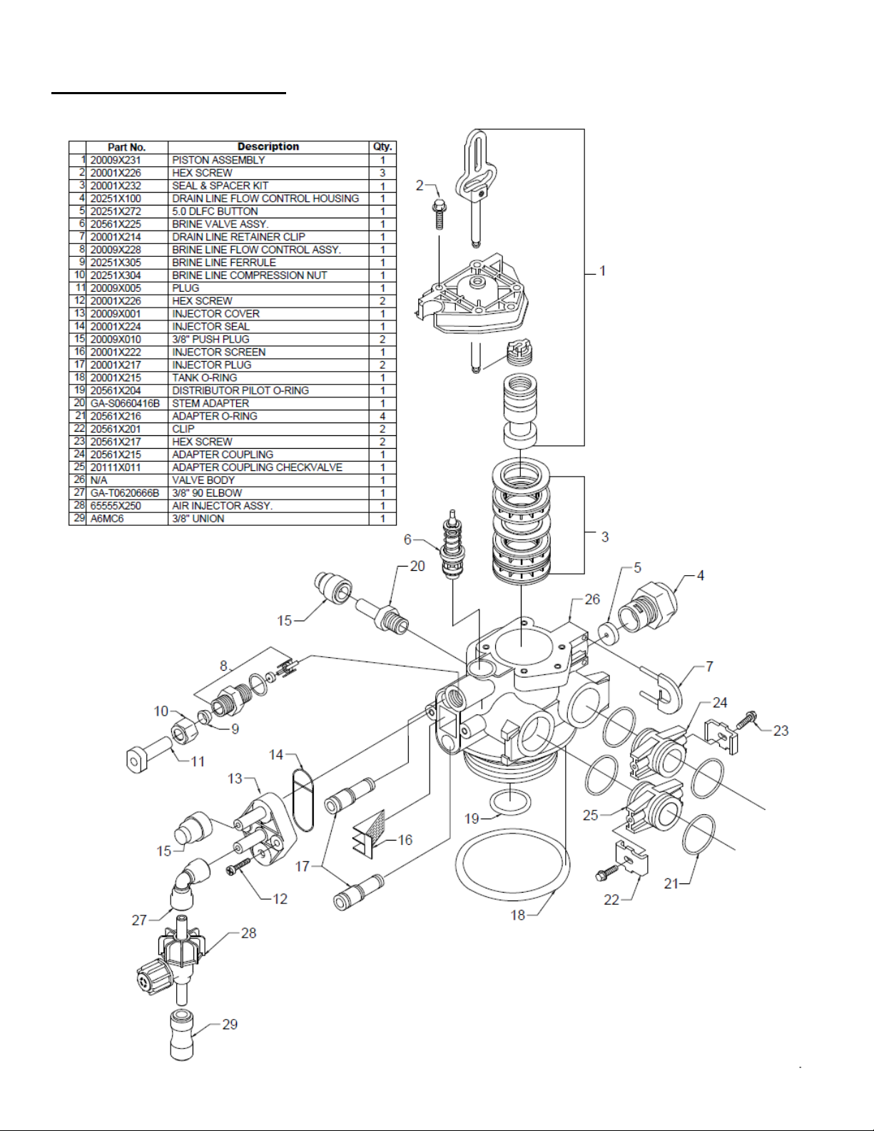
1. Pull out clip and remove drain line assembly located on the left side of control valve. Remove drain line hose elbow
and wrap threads with Teflon tape. Reinstall drain line hose elbow. Replace drain line assembly and reinstall clip.
Caution: Hand tighten only!
2. Install 1/2" I.D. drain line tubing (not included) from hose elbow to an open drain. A 4" gap between end of the drain
line and the open drain is required to prevent waste water backflow. Keep the drain line as short as possible. An
overhead drain line can be used if necessary, but should discharge below the control valve. A syphon trap (taped loop)
at the outlet of the drain line is advisable to keep the drain line full and assure correct flow during backwash. Elbows or
other fittings must be kept at a bare minimum.
Note: Where the drain line is elevated above the control valve or exceeds 20 feet in length, 3/4" I.D. drain line tubing
should be used.

- Electrical Connection -
1. Connect the power cord and plug power supply into a 115 volt / 60 Hz receptacle.
Note: Do not plug into an outlet controlled by a wall switch or pull chain that could inadvertently be turned off
Electronic Connections
P = Power Supply
B = Powered in Air Draw Cycle Only
S = Not Used
Normal Operation
1. Home Display
- Alternates between the display of Time of Day and Number of Days until the Next Regeneration.
- Days remaining until the Next Regeneration will count down from the entered Regeneration Day
Override Value until it reaches 1 day remaining.
- A Regeneration Cycle will then be initiated at the ne t designated regeneration time.
2. Battery Back-Up (Uses a standard 9-volt alkaline battery.)
- Installing the battery
- Features of Battery Back-Up
Maintains the Time of Day during power failures.
Notes: 1) During power failures, the display is turned off to conserve battery power. However, to confirm that the battery
is working, press either button and the display will turn on for five (5) seconds.
2) If power failure occurs while system is regenerating, the valve will motor to a shut off position to prevent
constant flow to drain. Note: Depending upon system pressure and other factors, it is possible to observe a
reduced flow to drain during this step. After power is restored, the valve will return and finish the cycle where it
left off prior to the power interruption.
3) When used without battery back-up, the unit acts like a standard valve. When a power failure occurs, the unit
stops at its current point in the regeneration position and then restarts at that point when the power is restored.
However, the time will be offset by the increment of time the unit was without power.
P B S

12:00
Main Menu
1. To enter Main Menu, press the Menu/Enter button.
(Time of Day will flash)
2. To set the Time of Day, press the Set/Change button.
(First digit will flash) Example [12:00]
- To change digit value, press the Set/Change button.
- To accept the digit value, press the Menu/Enter button.
- Ne t digit will flash to begin setting.
- Once the last digit display is accepted, all digits will flash.
3. To set A M or P M , press the Menu/Enter button.
- To change digit value, press the Set/Change button. Example [ ]
- To accept the digit value, press the Menu/Enter button.
- Once A.M. or P.M. is accepted, the ne t menu item will flash.
4. To set the Number of Days between Backwash Cycles (A), press the
Set/Change button.
- Repeat instructions from step (2). Example [ - 07 ]
Notes: 1) Ma imum value is 29.
2) If value set to 0, Automatic Regeneration will never occur.
3) Default setting is 6 days.
5. To set the Number of Days between Air Draw Cycles (d), press the Set/Change Button
- Repeat instructions from step (2) Example [ d – 01 ]
Notes: 1) Ma imum value is 29.
2) If value set to 0, air draw is turned off, but an air cycle will still be completed when
backwash cycle occurs. If the Number of Days between ir Draw Cycles is set to
a higher number of days than the Number of Days between Backwash Cycles, it
will have no effect. In order to turn off all cycles, both the Days between Backwash
and Days between ir Draw Cycles must be set to 0.
3) Default setting is 1 day.
6. To E it Main Menu, press the Menu/Enter button.
Note: If no buttons are pressed for 60 seconds, the Main Menu will be e ited automatically.
SET
CHANGE
MENU
ENTER
Set/Change
Button

Starting Extra Ba kwash Cy le
1. To Start Delayed Extra Cycle Example [ 1 ]
- If Days Remaining Until Next Regeneration does not read ‘1’, press and hold the
Set/Change button for 3 seconds until the display reads ‘1’.
-Regeneration cycle will initiate at the ne t designated regeneration time.
2. To start Immediate Extra Cycle
First complete above step.
- With Days Remaining Until Next Regeneration at ‘1’.
- Press and hold the Set/Change button.
- After 3 seconds, the regeneration cycle will begin.
3. To Fast Cycle thru regeneration
First complete above 2 steps.
Note: Fast Cycle is not necessary unless desired to manually step through each cycle step.
-Press and hold the Set/Change button for 3 seconds to advance to the ne t cycle step.
Side Ki k Default (min.)
Step 1 : Air Release Up to 5
Step 2 : Backwash 10
Step 3: Rest 5
Step 4 : Air Replenish 20
Step 5 : Rapid Rinse 10
Note: Depending upon system pressure and
other factors, it is possible to observe flow to
drain in the rest cycles.

Set Up Procedures
1. Move the bypass valve slowly to the Service position or open the main valve and allow water to flow to the mineral
tank.
2. When the water stops flowing into the tank, open a treated water tap and allow air to be released from the lines. Allow
several minutes during this time to follow steps on valve for setting the time. Once time of day is set, go back to main
menu. Then close the tap. Open the bypass valve or main valve completely. The days for backwash and air draw are
already programmed.
Anytime media (other than very fine mineral on initial startup) is apparent in the service lines, it usually indicates one of
the following problems:
A. The unit is plumbed in backward allowing the media to be carried in the service line.
B. The distributor tube inside the tank is not seated inside the valve or is damaged in some way.
C. If the media flows to the drain during backwash, after a reasonable period of soaking, check the drain line flow
control to be sure that excessive water is not going to the drain allowing mineral to siphon out of the tank.
3. Hold down set/change button for five (5) seconds. (A “1” will appear), release and repeat. The unit will now enter
backwash. Allow the unit to perform an entire cycle. This will rinse media and charge up the air chamber.
4 Once unit is back in service, clean water will be available, approximately “60” minutes. Any water used during a
cycle will be untreated.
- Final Checkout -
1. Be certain that the bypass valve is in Service position or main valve is completely on.
2. Check electrical supply to be certain the cord is connected to an uninterrupted 115 volt outlet.
3. Be certain the warranty card is filled out and mailed in.
4. Leave this manual with the homeowner.
Important Notice - The plumbing system, piping, pressure tank, hot water tanks, softeners, etc. that have been exposed
to iron bearing water may need to be cleaned of the precipitated iron that has been collected in them or iron bleed thru
may be a problem. We suggest all tanks be drained and flushed thoroughly.

POWER HEAD ASSEMBLY

Valve Body Assembly


10 - 7 - 5 - 1
“LIMITED” WARRANTY
Water Treatment Equipment
During the time periods and subject to the conditions hereinafter set forth, CSI Water Treatment, will repair or replace to the original user or consumer,
any portion of your new CSI Water Treatment product which proves defective due to defective materials or workmanship of CSI Water Treatment.
Contact your nearest authorized CSI Water Treatment dealer for warranty service. At all times CSI Water Treatment shall have and possess the sole
right and option to determine whether to repair or replace defective equipment, parts, or components. Damage due to conditions beyond the control of
CSI Water Treatment is NOT COVERED BY THIS WARRANTY. (Contact parcel or Freight Company for claims on freight damage in transit.)
WARRANTY PERIODS:
I
TEM
*10
YRS
.*7
Y
RS
. *5
Y
RS
.*1
Y
RS
.
I
TEM
*5
Y
RS
. *1
Y
RS
.
Residential Mineral Tanks
●
Brine Tank Components
●
Commercial Mineral Tanks
●
Microcline
™
Reverse Osmosis Systems
●
Proprietary Control Valves
●
Other Residential RO Systems
●
Other Softener/Filter Control Valves
●
Other Accessories & Parts
●
Brine Tank (30” or smaller)
●
Commercial Reverse Osmosis – 1 year from ship date
Brine Tank (39” or larger)
●
- Pumps & membranes are pro-rated per month
* From Date of Installation
LABOR, ETC., COSTS : CSI Water Treatment shall IN NO EVENT be responsible or liable for the cost of field labor or other charges incurred by any
customer removing and/or reaffixing any CSI Water Treatment product, part or component thereof.
THIS WARRANTY WILL NOT APPLY : (a) To defects or malfunctions resulting from failure to properly install, operate or maintain the unit in
accordance with printed instructions provided; (b) to failures as a direct result of the incoming water quality, (c) to failures resulting from abuse, accident
or negligence; (d) to normal maintenance services and parts used in connection with such service; (e) to units which are not installed in accordance
with applicable local codes, ordinances and good trade practices; (f) if the unit is moved from its original installation location; (g) unit is used for
purposes other than for what it was designed and manufactured, and (h) filter media and exchange resins.
RETURN OF REPLACED COMPONENTS: Any item to be replaced or repaired under this Warranty must be returned to CSI Water Treatment in
Ashland, Ohio, or such other place as CSI Water Treatment may designate, freight prepaid.
PRODUCT IMPROVEMENTS: CSI Water Treatment reserves the right to change or improve its products or any portions thereof without being obliged
to provide such change or improvement of units sold and/or shipped prior to such change or improvement.
WARRANTY EXCLUSIONS : As to any specific CSI Water Treatment product, after the expiration of the time period of the warranty applicable thereto
as set forth under the heading “Warranty Periods” above, THERE WILL BE NO WARRANTIES, INCLUDING ANY IMPLIED WARRANTIES OF
MERCHANTABILITY OR FITNESS FOR ANY PARTICULAR PURPOSE.
Some states do not allow limitations on how long an implied warranty lasts, so the above limitation may not apply to you. No warranties or
representations at any time made by any representative of CSI Water Treatment shall vary or expand the provisions hereof.
LIABILITY LIMITATION: IN NO EVENT SHALL CSI WATER TREATMENT BE LIABLE OR RESPONSIBLE FOR CONSEQUENTIAL, INCIDENTAL
OR SPECIAL DAMAGES RESULTING FROM OR RELATED IN ANY MANNER TO ANY CSI WATER TREATMENT PRODUCT OR PARTS
THEREOF.
Some states do not allow the exclusion of limitation of incidental or consequential damages, so the above limitation or exclusion may not apply to you.
The Warranty gives you specific legal rights and you may also have other rights which vary from state to state.
In the absence of suitable proof of installation date, the effective date of this warranty will be based upon the date of manufacture plus thirty (30) days.
Direct all notices, etc. To: Service Department, CSI Water Treatment, 710 Orange Street, Ashland, Ohio 44805 Date: June, 2015
Table of contents
Other CSI Water Dispenser manuals
Popular Water Dispenser manuals by other brands

LF
LF Matic Instruction and maintenance

H2oEliteLabs
H2oEliteLabs EWC-MAX-i Operation manual

Lancaster Water Treatment
Lancaster Water Treatment X-FACTOR Series Installation, operating and service manual

Everpure
Everpure RT-9 Specifications

Canature WaterGroup
Canature WaterGroup 85HE owner's manual

DS Services of America
DS Services of America 100 Series manual

l'eau miracle water
l'eau miracle water Miracle Water MW-15 owner's manual

Dahlert
Dahlert DT-WP-22 instruction manual

GE
GE Profile GXCF35GBSR owner's manual

Elkay
Elkay EMASM Installation and use manual

KitchenAid
KitchenAid KHWC160 Series Installation instructions and use and care guide

icetro
icetro ID-0160-AN user manual