CSL DigiAir Pro 3 User manual

DIGIAIR PRO 3
DigiAir Pro 3
Introduction
The DigiAir Pro 3 range offers installers easier, faster installation of a professional
signalling system with even greater resilience, plus access to CSL Live, our ordering
and management portal.
Using the onboard serial connections, pins triggering or dial capture, DigiAir Pro 3 is
compatible with a wide range of control equipment including systems installed to
EN50136 & PD6662. The range consists of DigiAir Pro 3 Radio and DigiAir Pro 3 LAN -
our single-path solutions that utilise either a Radio path or LAN to signal an alarm.
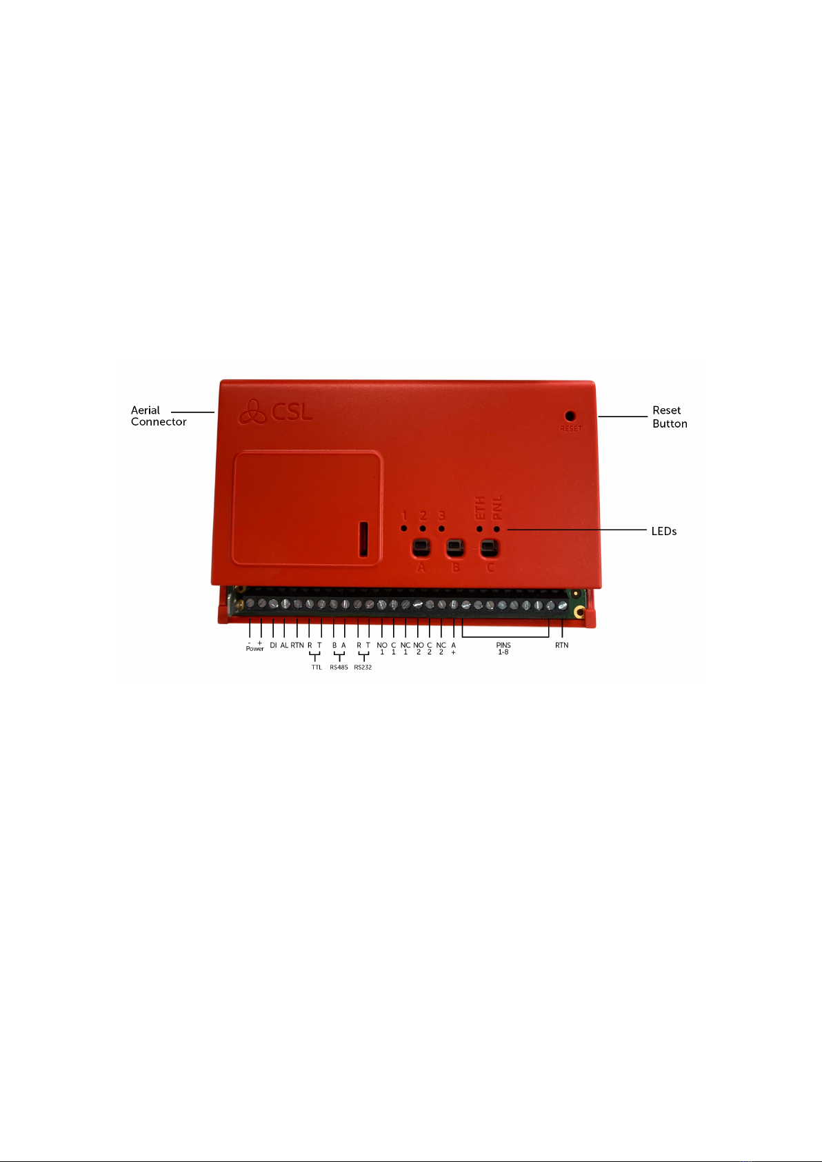
Figure 1 - Exploded View of DigiAir Pro 3

DigiAir Pro 3
Step 1 - Site Survey
DIGIAIR PRO 3 - RADIO
Use a Signal Analyser (available from the CSL Installer Shop) to determine if enough
base stations (2 or more) are available at the site and that they can supply sufficient
signal strength (30% and above). This will determine the optimum location for the
DigiAir Pro 3’s aerial to be mounted.
If you do not have a Signal Analyser, we recommend powering up the DigiAir Pro 3,
connecting the aerial/s, going through the commissioning process then checking the
signal strength before permanently fitting the aerial.
Press the A button to show the signal strength - LED 1 should be green to show an
acceptable level of Radio signal/quality. See View Signal Strength section for more
information.
DIGIAIR PRO 3 - LAN
DigiAir Pro 3 uses DHCP as the default IP settings. Fixed IP settings can be added or
amended using the My Base App. Fit the Ethernet Cable to the device and connect to
the customer’s router. Ensure the customer’s LAN socket is live and their network
allows access to the CSL servers through their firewall
• IP ranges 185.201.164.0/22 & 139.28.100.0/22
• Port 50561 open for outbound traffic
• NAT enabled
• UDP data
The ETH LED will flash between red, amber and green to indicate the connection is
operational and data is being seen on the local network link.

DigiAir Pro 3
Step 2 - Installation
DigiAir Pro 3 must be installed within an enclosure suitable for the installation
certification. The unit should be fixed securely using the adhesive pads supplied or
via the screw fixings accessible by removing the lid.
Once fitted, ensure:
• The aerial is connected or the ethernet cable is installed, as appropriate
• The alarm panel or PSU is powered down
• Wire the DigiAir Pro 3 in this order.
1. Negative (-) power,
2. Positive (+) power,
3. Serial cable or inputs
• If required, connect the serial cable - RS485, RS232 or TTL (panel dependent) – see
Panel Connections section for more information
• Connect any hardwired alarms into the device – see Pin Triggering section for more
information
• Connect the fault output
• Restore power to the alarm panel or PSU
IN ORDER TO MAINTAIN COMPLIANCE WITH THE REQUIREMENTS FOR
ELECTRICAL SAFETY THE DIGIAIR PRO 3 SHOULD BE POWERED FROM A
FUSED CONNECTION WITH THE FOLLOWING RATING:
• FOR A 12V DC SYSTEM (SUPPLY VOLTAGE IN THE RANGE 10V TO
14V DC) A FUSE RATED AT 1.25 A
•FOR A 24V DC SYSTEM (SUPPLY VOLTAGE IN THE RANGE 20V DC
TO 36V DC) A FUSE RATED AT 600 MA
IF THE POWER SOURCE IS NOT LIMITED TO THESE VALUES, THEN A FUSE
WITH THE CORRECT RATING MUST BE FITTED IN LINE WITH THE POSITIVE
CONNECTION FROM THE POWER SOURCE.
POSITIONING AERIAL
DO • INSTALL VERTICALLY IN AN OPEN SPACE.
• COMPLETE A SIGNAL TEST BEFORE INSTALLING IN THE FINAL POSITION.

DON'T
• INSTALL CLOSE TO METAL OR SOURCES OF INTERFERENCE, E.G. WIRING,
LIGHTING, ELECTRICAL INSTALLATIONS, COMPUTERS, MONITORS, ROUTERS
& OTHER EQUIPMENT.
DigiAir Pro 3
Step 3 - Commissioning
On power-up, the DigiAir Pro 3 will automatically contact the Gemini Global Platform
to perform its commissioning process, which can take up to 5-8 minutes.
Once commissioned, all 3 LEDs will light green for 5 seconds. The device will then
reboot.
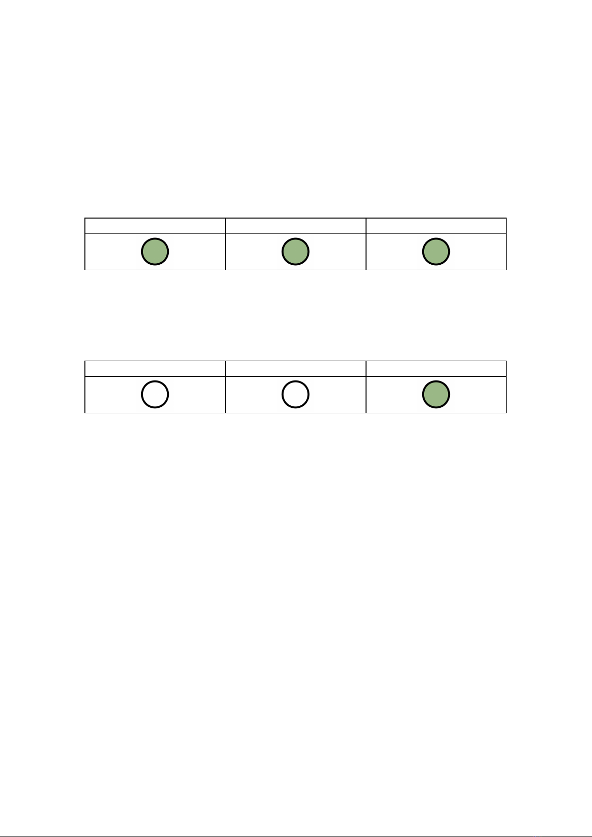
LED 1 - Power LED 2 - Comms Path LED 3 - Commissioned
Figure 2 - Commissioning
On next boot, LED 3 will go green to indicate that the device is fully commissioned.
LED 1 - N/A LED 2 - N/A LED 3 - Device Status
Figure 3 - Quiescent/Normal State
If using input pins, whilst in quiescent/normal state, press button C for 5 second to
self-learn the current panel input status. LED 3 will flash amber then red and return
to sold green once completed.

DigiAir Pro 3
Step 4 - Testing
Before leaving site you must test the DigiAir Pro 3 device as per these steps.
1 - Place device on test at the ARC and send a range of signals from the panel
2 - Perform a path test by tapping button C whilst in quiescent/normal state
3 - LED 3 will flash to show signals are being sent
4 - Check signals are received at the ARC
See Troubleshooting for further details.

DigiAir Pro 3
Customising the DigiAir Pro 3
All device programming can be performed using the My Base App or website.
Download the app from App Store or Google Play and enter your credentials.
Alternatively in a browser go to My Base.
If need be, you can use the one-time access page to install a device using your
mobile phone or web browser without login details. Follow this link and enter the
device serial number and connection ID.
USING THE BUTTONS & LEDs
Once commissioned, the DigiAir Pro 3 enters the quiescent or normal state. In this
state, LED 3 will show the device status and there will be no other activity on LED 1
or 2. See Figure 3 - Quiescent/Normal State above. The LED colour indicates the
current status
• Green = path and system are OK
• Amber = path is not working
• Red = error
From this state you can
• Press Button A to view the signal strength/LAN connectivity
• Press Button C to generate a Test Call
• Press and hold Button C to execute Pin Learn
VIEW SIGNAL STRENGTH
Press Button A once to view the signal strength. LED 1 will show the
signal/connectivity status of your path.
• Solid green = good signal
• Flashing green = acceptable signal
• Flashing amber = emergency, only/low signal available (move aerial)
• Flashing red = SIM not ready/no signal available (move aerial).
• Red = error
VIEW LAN CONNECTIVITY
Press Button A once to view the LAN connectivity. LED 1 will show the connectivity
status of your path.
• Solid green = good connection
• Amber = connection to local network is good but no access to internet/CSL
• Red = error – check the ethernet cable and ETH LED

Press Button A again to return to Quiescent/Normal State.
LED 1 - Primary Path LED 2 - N/A LED 3 - N/A
Figure 4 - Connectivity
GENERATE A TEST CALL
Press Button C once from Quiescent/Normal State to send a Test Call
EXECUTE PIN LEARN
From the Quiescent/Normal State, press and hold Button C for 5 seconds to allow the
device to perform a self-learn of the current input pins. LED C will flash once
complete. See Pin Triggering for more information.

DigiAir Pro 3
Panel Integrations
Your device will come pre-configured to connect to the panel using pin triggering. In
My Base it will show Panel Type = pins only.
A panel can also be connected using
• Dial Capture (PSTN Modem)
• TTL
• RS232 (including ATS 7090)
• RS485
• Ethernet
To enable any of these connections to a control panel, install the appropriate cabling
then go to the My Base App and select the correct panel type. See Panel Integrations
for more information.
Panel guides can be found by
• Clicking the panel type (after selection) via the My Base App
• Scanning the QR code below
• Visit the Installer Zone on our website.
PIN TRIGGERING
For this operation, the device is triggered by removing or applying zero volts to input
terminals 1-8. No external pull-up resistors will be required. This is generally
achieved via the digital communicator outputs of a control panel. On receiving an
input to the pin terminals, the unit will signal alarm conditions and will generate the
relevant messages and forward them via the Gemini Global Platform to the ARC.
Installers are advised that the intended use should avoid situations where the rate of
trigger exceeds the rate at which messages are received at the ARC receiver.
Control Panel DigiAir Pro 3
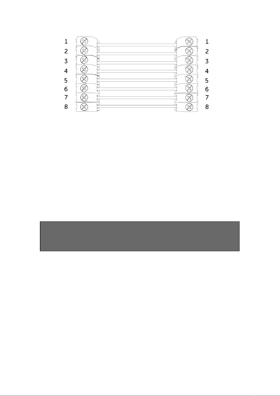
Figure 5 – Example of pin triggering wiring
CONFIGURING PIN INPUTS
To self-learn the current panel input status, press button C whilst in
quiescent/normal state for 5 seconds. LED 3 will flash red twice once completed.
To change the input from negative removed or applied to positive removed or
applied, change the pin bias via My Base under the Hardware menu button and use
the A+ terminal instead of RTN.
IF YOU CANNOT CHANGE THE PANEL’S POLARITY AND YOU DO NOT HAVE
ACCESS TO MY BASE OR THE WEBSITE, PLEASE SPEAK TO OUR TECHNICAL
SUPPORT TEAM.
DualCom Pro pin inputs 1, 2, 3, 5 – 8 generate SIA untyped alarms UA/UR8001 to
8012 on standard product configuration e.g.
[#123456|NUA8001|AChannel 1 Alarm]
[#123456|NUR8001|AChannel 1 Restore]
DualCom Pro pin 4 Open / Close inputs generate SIA alarm OP and CL OP/CL8004 on
standard product configuration e.g.
[#123456|NOP8004|ASystem Set]
[#123456|NCL8004|ASystem Unset]
CONFIGURING OUTPUTS
Both outputs can be configured as either Normally Open (NO) or Normally Closed
(NC), as required. Output 1 is defaulted to indicate a total path fail condition to the

control panel. Output 1 can be reconfigured to indicate another path failure type,
Output 2 can be configured to indicate a path fail condition or be used as a manual
trigger. To make any amendments please use the My Base App.
IF THE DEVICE IS POWERED BY A 24V (FIRE PANEL) SUPPLY, THE A+
TERMINAL WILL STILL DELIVER 12V
Figure 6 - Example of Fault Output Wiring
PANEL CONNECTIONS
DIAL CAPTURE
DigiAir Pro 3 simulates and replaces the phone line connection to the control panel’s
Digi-Modem. The control panel’s Digi-Modem must use one of the following alarm
formats: Fast Format*, Contact ID or SIA. In the event the control panel needs to
send a signal to the ARC, DigiAir Pro 3 will capture the message and forward it, via
Gemini, to the ARC. The Digi-Modem must have an ARC telephone number (ie 01)
and account number (i.e. 1234) programmed for Dial Capture to work. If you want to
monitor the Dial Capture connection, you will need to connect an output configured
as PSTN line fault on your control panel, to one of the DigiAir Pro 3’s inputs. That
input then needs to be designated as Dial Capture Fail at your ARC.
*Please confirm compatibility of Fast Format with DigiAir Pro 3 via your ARC.
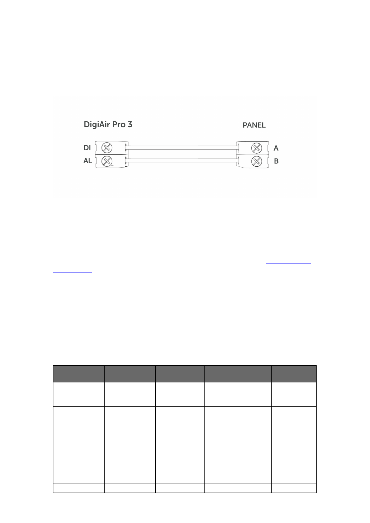
Figure 7 - Dial Capture Wiring
DC09 CONNECTIONS
Only the DigiAir Pro 3 LAN can connect to a panel using DC09. The panel and the
DigiAir Pro 3 must both be connected to the customers LAN. See the Generic DC-09
TCP/IP Guide for set up instructions.
SERIAL / RS232 / 485 / TTL PANEL CONNECTIONS
As standard, DigiAir Pro 3 is supplied with a serial cable compatible with Honeywell
(RS485), Orisec (TTL), Pyronix (RS232), Texecom (TTL) and HKC (TTL) panels. Other
types may require an additional cable/plug-in that can be purchased on our Installer
Shop. It is possible to use pins and serial cable together, if required.
MANUFACTURER PANEL CONNECTION CABLE
PLUG WIRE CONNECTOR
Honeywell Galaxy RS485
4 Pin
(cable
provided)
Green RTN
Blue RS485-B
Red RS485-A
Orisec All TTL
4 Pin
(cable
provided)
Green RTN
Blue TTL-T
Red TTL-R

Pyronix Euro/Enforcer RS232
6 Pin
(cable
provided)
Green RTN
Blue RS232-R
Red RS232-T
Texecom Premier/Elite TTL
5 Pin
(cable
provided)
Green RTN
Blue TTL-R
Red TTL-T
HKC 1070/10270 TTL
4 Pin
(cable
provided)
Green TTL-R
Blue RTN
Red TTL-T
Figure 8 – Panel Connection Information
Figure 9 – Serial Cable (RS232/485/TTL)
YOU MUST POWER DOWN THE CONTROL PANEL AND DUALCOM DIGIAIR
PRO 3 BEFORE CONNECTING THE SERIAL LEAD, TO AVOID DAMAGE.
For RISCO, Eaton, UTC and other panels, please purchase the relevant cable from
CSL Live. For other connections or further instructions on Control Panel
programming, panel guides can be found by clicking the panel type (after selection)
via the My Base App, by clicking the link below or visiting the Installer Zone of our
website.
CLICK HERE TO FIND YOUR PANEL
DigiAir Pro 3
My Base App
My Base provides Installers with the ability to manage and configure DigiAir Pro 3
devices on a handy App/Web portal.
Simply download CSL My Base from your appropriate App store and obtain log-in
information from CSL
(or the CSL web administrator within your company) to access these great features:
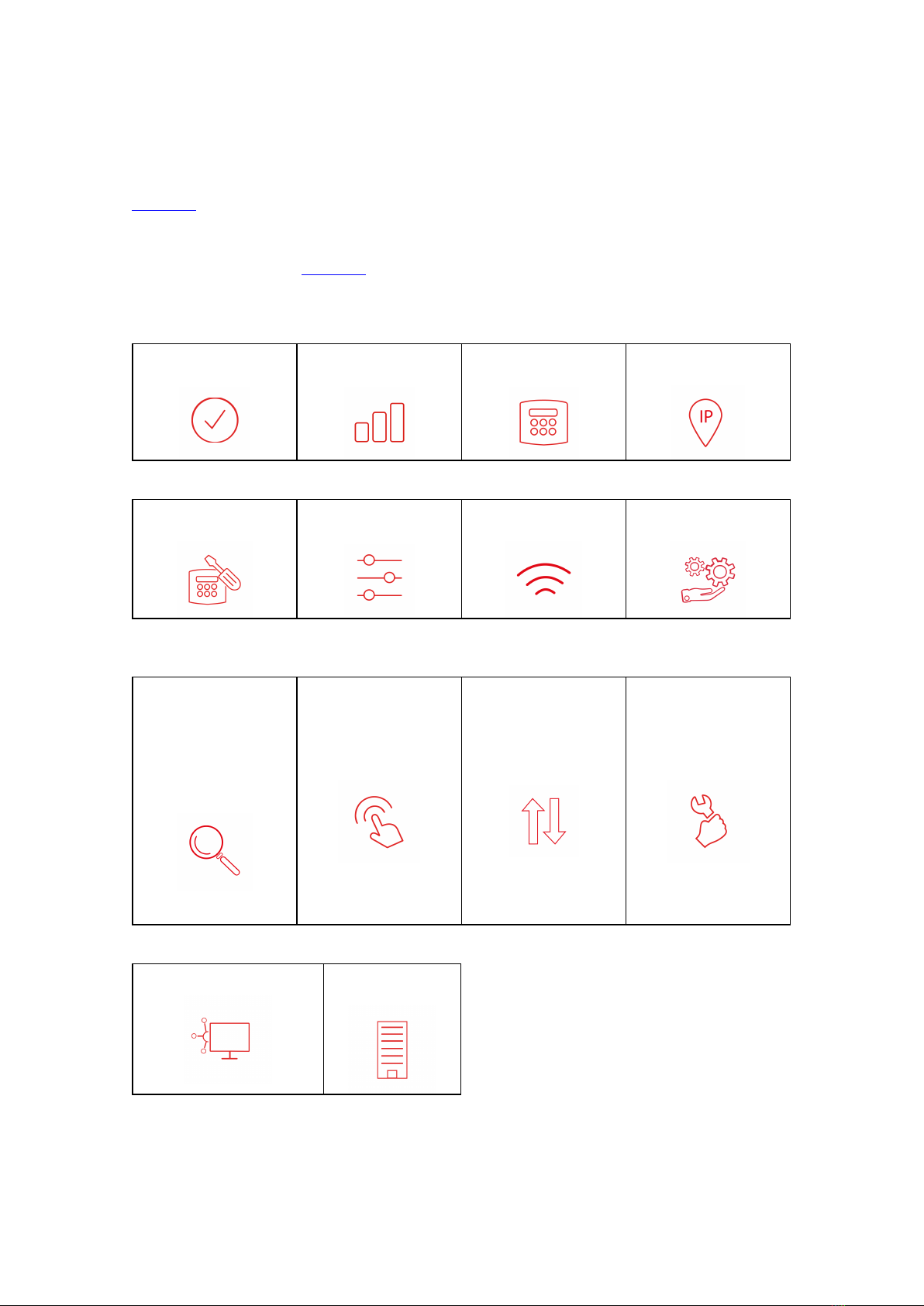
View path
status
Check signal
strength
View panel
connection status
Configure static IP
information
Amend panel
connection Change pin
configuration
Check ATS path
availability
Remotely upgrade
device firmware
View Alarms
(you must still check
with your ARC that
alarms are being
received by them)
Test
Alarm Invert fault
relay
Configure
outputs
Amend Smart Reporting Add estate
name
DigiAir Pro 3
Troubleshooting
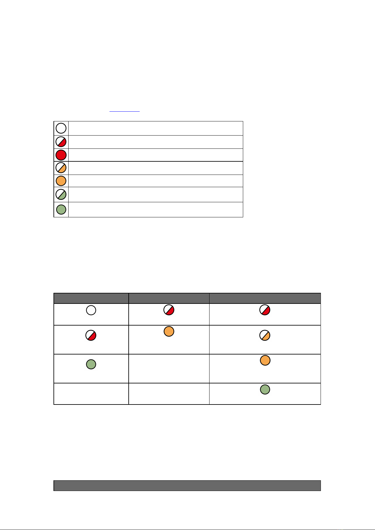
Interpreting the LEDs
The LEDs provide summary information as to the state of the device is. For further
information go to My Base.
LED off
Red Flashing
Red Solid
Amber Flashing
Amber Solid
Green Flashing
Green Solid
Figure 10 - LED Key
As the DigiAir Pro 3 powers up for the very first time it will run through its
commissioning process. You will need to wait for LEDs 1, 2 & 3 to go green before
the unit reboots.
LED 1 LED 2 LED 3
No power No comms No comms
Power start up 1 path comms (dual-path
systems) Comms path found
Power on Commissioning server found.
Contacting alarm server
Fully commissioned
Figure 11 – Commissioning LEDs
Once commissioned, the unit will return to its quiescent/normal state. LED 3 should
be visible and LEDs 1 & 2 will be off. LED 3 will show you whether the unit has any
errors or is transmitting data.
LED 3
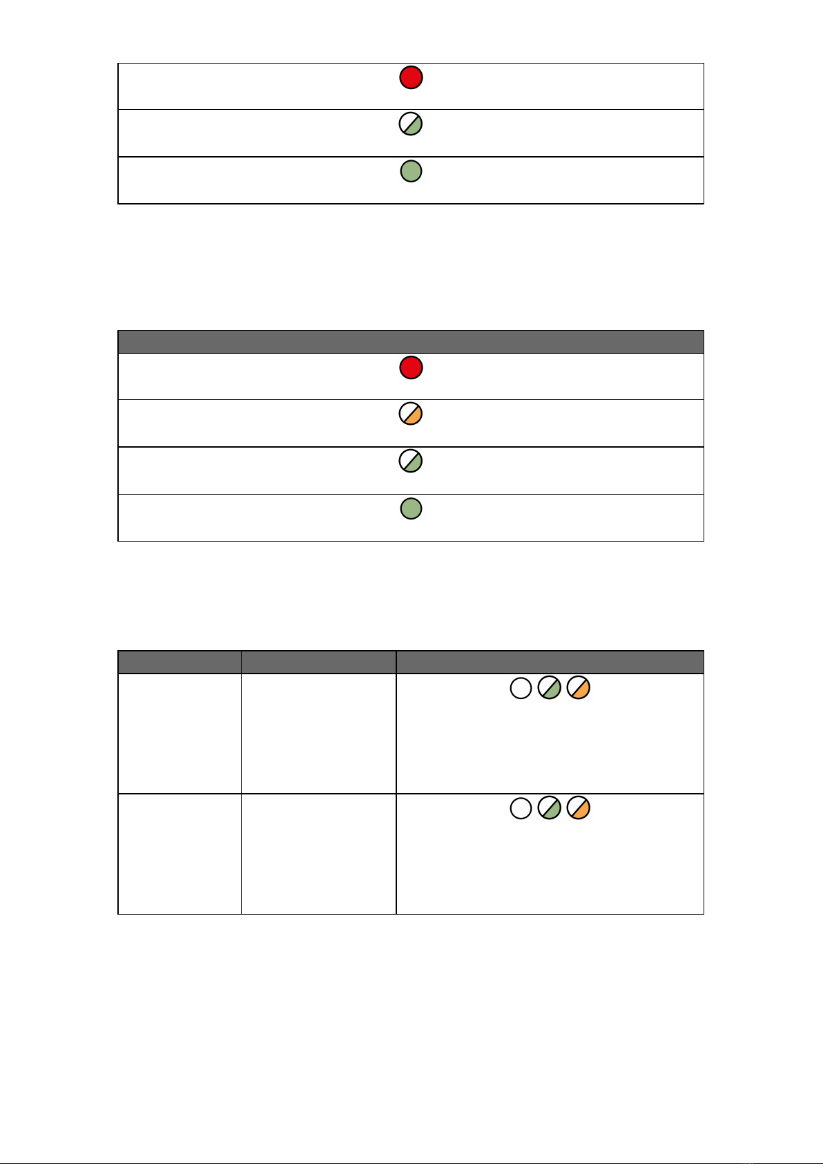
Error found on the device (no commissioning performed)
No errors found and the device is currently transmitting or receiving data
Operating normally
Figure 12 - Quiescent/Normal State LEDs
From the quiescent/normal state, press button A. Only LED 1 will show.
LED 1
No signal / SIM not ready or LAN not connected
Registering / Signal is unacceptable / LAN connected but cannot transmit data
Signal is acceptable (3/10) but could be improved
Signal 4/10 (or above) or LAN connected
Figure 13 – Connectivity Section
There are 2 additional LEDs shown as PNL and ETH.
LED DESCRIPTION LED DESCRIPTION
PNL Serial connection to
panel
Indicates if any of the serial connections to
a panel are in use. If the LED is flashing
green, data is being transferred. This LED
will not be lit if there is no serial integration
to the panel.
ETH LAN connection to
customer’s network
Indicates if there is a LAN connection to the
customer’s router. If the LED is flashing
green, data is being detected on the local
link. This LED will not be lit if there is no
physical LAN connected.
Figure 14 – Additional LEDs
RADIO ONLY TROUBLESHOOTING
Q. How can I fail my signalling paths without having to disconnect them?
A. To fail each path, from Quiescent/Normal state, press Button A. Press and hold B

for 5 seconds to fail the primary path. The path will stay in fail for 15 mins unless you
tap B again to restore the path.
Q. How can I check the signal strength of each radio module?
A. You can check the signal strength of the radio module on a commissioned device
via the My Base App. Alternatively, when in the quiescent/normal state, you can
press button A to toggle to the connectivity menu. Once there, LED 1 (first path) will
show you the signal strength. We recommend a solid green LED (40% or 4/10 and
above).
Q. Does my unit have a roaming SIM?
A. Yes, all DigiAir Pro 3 Radio devices come with 2 Roaming 4G SIMs
Q. My signal strength is 30% (3/10) or less or my LED is orange/red. What
can I do to improve it?
A. You can improve this by:
• Avoiding coiling the aerial cable
• Moving the aerial away from electrical equipment/wiring
• Moving the aerial to a higher point in the property or closer to a window/door
LAN TROUBLESHOOTING ONLY
Q. Why is my LAN path not working if my ETH LED is flashing green?
A. This means the device can see it is connected to the customer’s router but there
is a network configuration error. This type of fault can be due to the below:
• The network administrator has not amended the firewall rules as required. The
required information can be found in the “Customer IT Survey Form” on the installer
zone.
• If the device requires static IP addresses and these have not been added to the
“Edit LAN Config” section of My Base. As standard the site records are setup with
DHCP.
Q. Why is my ETH LED not flashing if I have connected the ethernet cable to
the device?
A. This means the device is not able to see a physical connection. We would advise
testing the RJ45 ethernet cable and also making sure the port the cable is plugged
into is live and not disabled/suspended.
Q. Does my device require static IP addresses?

A. No, it will also work with DHCP.
Q. Does the DigiAir Pro 3 support any type of negotiation speed?
A. No, the DigiAir Pro 3 will only support negotiation speeds of up to 100Mbps.

DigiAir Pro 3
Technical Specifications
Dimensions Radio: 75 mm (h) x 115mm (w) x 16mm (d)
LAN: 75mm (h) x 115mm (w) x 23mm (d)
Weight 106g excluding aerial
Temperature -10 °C to + 55 °C
Humidity 0 - 90% non-condensing
Mounting Via fixing points under main cover
Warranty 5 years
Power
Requirement
10 - 36 Volts.
In order to maintain compliance with requirements for electrical safety the
Dualcom Pro should always be powered from a fused supply with following
rating:
• For a 12V DC system (supply voltage in the range 10 Volts DC to 14 Volts
DC) a fuse rated at 1.25
• For a 24V DC system (supply voltage in the range 20 Volts DC to 36 Volts
DC) a fuse rated at 600 mA
If the power source is not limited to these values, then a fuse with the correct
rating must be fitted in line with the positive connection from the power
source.
The SPT will shut down on detecting a low supply of 7.6 Volts DC +/- 0.5 Volts
DC
Current
Consumption
DigiAir Pro 3 Radio attached to Security Panel: 66 mA (average value)
DigiAir Pro 3 Radio attached to Fire Panel: 55 mA (average value)
DigiAir Pro 3 LANattached to Security Panel: 78 mA (average value)
DigiAir Pro 3 LAN attached to Fire Panel: 62 mA (average value)
Radio Path 2G, 3G, 4G
Output Ratings Maximum applied voltage = 60V
Maximum current = 150mA
Aerial 50 ohms (nominal) on MMCX socket
Operation Method Store and forward
CIE
Interconnections Input triggering (standardised parallel), RS232, RS485, TTL
RCT Protocols SIA
Input Terminals Max +30 Volts, Min 0 Volts DC (reference supply 0V) with a + or – 40%
change for > 200ms.
User Serviceable
Parts There are no serviceable parts within the DualCom Pro Range
Applicable
Standards
Suitable for use in alarm systems complying to:
• EN50131-1:2006+A2:2017
• EN50136-1:2012+A1:2018
• PD6662:2017
• PD6669:2017
Emissions Standard – Radio Equipment Directive 2014/53/EU (RED) EN
50130-5 Environmental Class II
ATS Classification EN 50136-2:2013 SP2, SP3, SP4
ATS Configuration EN 50131-10:2014 Type Y
ATS Classification EN 50136-1-1:1998
• Radio D3, M3, T4, S2, I3, A4 (ATS5)
• LAN D3, M3, T4, S2, I3, A4 (ATS5)
Other manuals for DigiAir Pro 3
1
Table of contents
Popular Industrial Equipment manuals by other brands

ABB
ABB HT611117 Operation manual

Endress+Hauser
Endress+Hauser Cleanfit P CPA471 operating instructions

Fröling
Fröling GAR 110 Installation and operating instructions

Toray
Toray NHPA Series instruction manual

Central Machinery
Central Machinery 5907 Owner's manual & safety instructions

ITEM
ITEM PS 4-20 installation guide

SUHNER MACHINING
SUHNER MACHINING BEW 12 Technical document

Clark-Reliance
Clark-Reliance Levalarm EA100 Series Instructions for installing and operating

ABB
ABB GOE 2600 Installation and commissioning guide

Zook
Zook RE2 installation instructions

Tomra
Tomra AUTOSORT user manual

CommScope
CommScope ADCP-90-326 user manual


