ABB GOE 2600 User manual

1ZSC000563-AAF EN, REV. 4, 2021-06-23
Transformer bushing, type GOE 2600
Installation and commissioning guide

The information contained in this document may be subject to change without prior warning and should not be considered
as binding on Hitachi ABB Power Grids’s behalf. Hitachi ABB Power Grids accepts no liability for any errors that may
appear in this document. Hitachi ABB Power Grids is not liable for any damage resulting from the incorrect interpretation
of this document. This document, or parts thereof, may not be reproduced or copied without Hitachi ABB Power Grids’s
consent. It may not be distributed to others or used by unauthorized parties. Any breaches to the above will be penalized
with the support of applicable laws.

Installation and commissioning guide
1ZSC000563-AAF EN, REV. 4, 2021-06-23
3
Contents
1 Safety 5
1.1 Levels of safety risks ................................................................................................................................................................... 5
1.2 Hazardous working situations ..................................................................................................................................................... 6
1.3 Safety precautions....................................................................................................................................................................... 6
1.4 Competence level........................................................................................................................................................................ 6
2 Product description 7
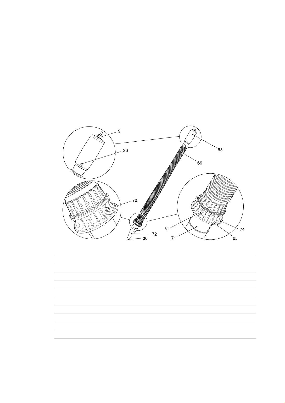
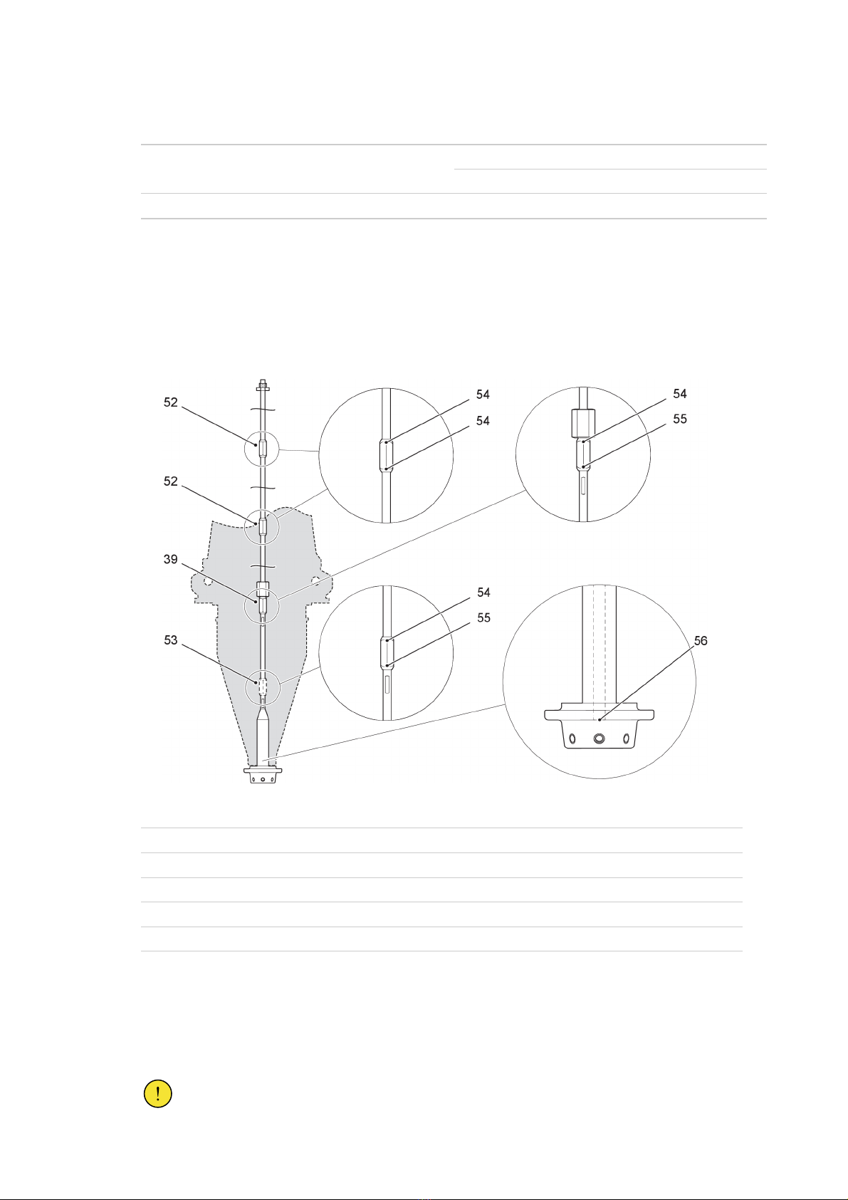
2.1 Design ......................................................................................................................................................................................... 7
2.2 Technical specifications............................................................................................................................................................... 10
2.2.1 General specifications ............................................................................................................................................... 10
2.2.2 Mechanical loading.................................................................................................................................................... 11
3 Delivery 13
3.1 Incoming inspection..................................................................................................................................................................... 13
3.2 Transportation ............................................................................................................................................................................. 13
3.3 Storage........................................................................................................................................................................................ 13
3.4 Lifting........................................................................................................................................................................................... 14
3.4.1 Lifting the transport box............................................................................................................................................. 14
3.4.2 Lifting the bushing out of the transport box ............................................................................................................... 15
4 Installation 19
4.1 Tools ............................................................................................................................................................................................ 19
4.2 Consumables .............................................................................................................................................................................. 19
4.3 Preparations ................................................................................................................................................................................ 20
4.3.1 Installation of lifting tools ........................................................................................................................................... 20
4.3.2 Lifting the bushing for installation on the transformer................................................................................................ 22
4.4 Installation at the transformer factory .......................................................................................................................................... 24
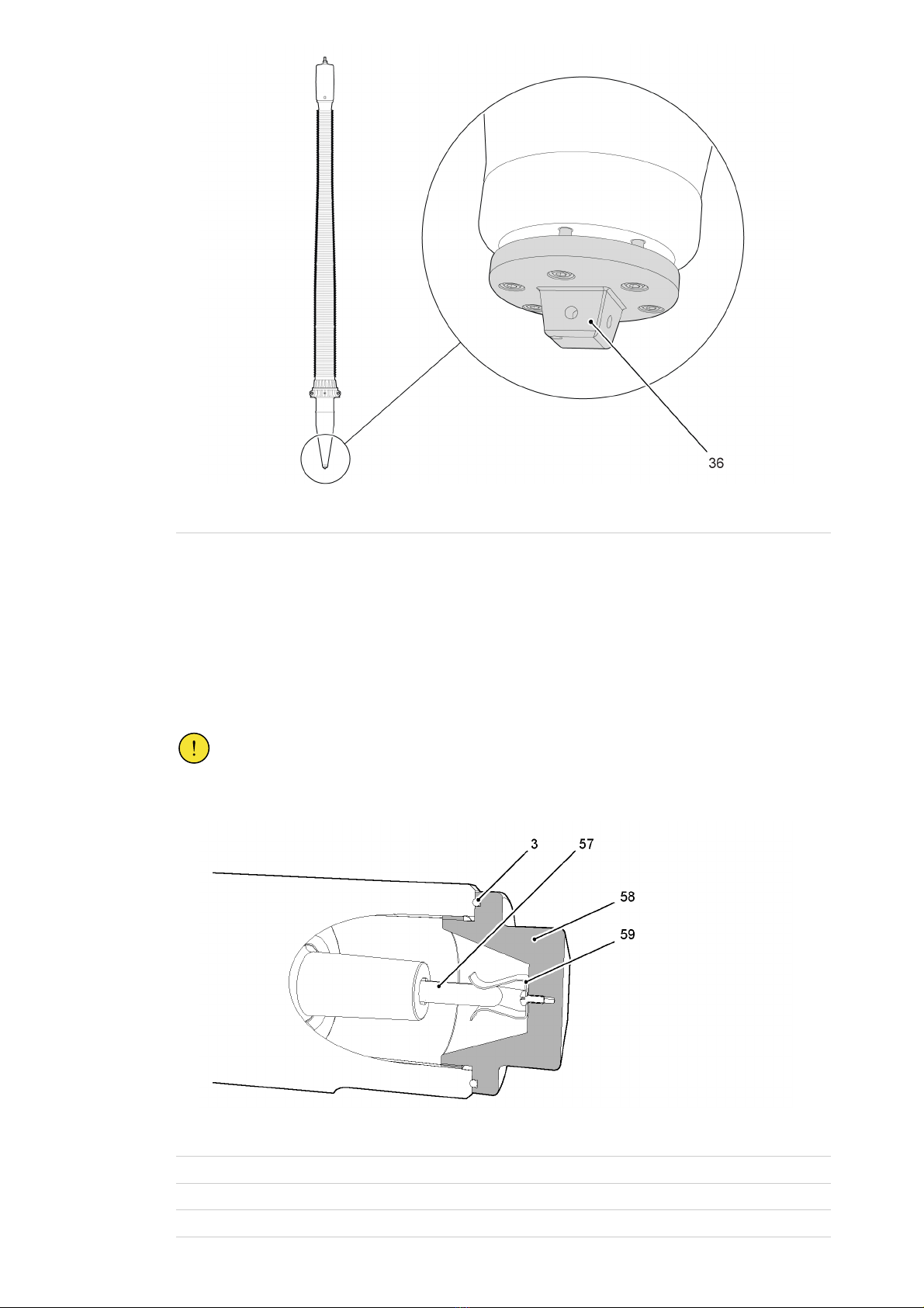
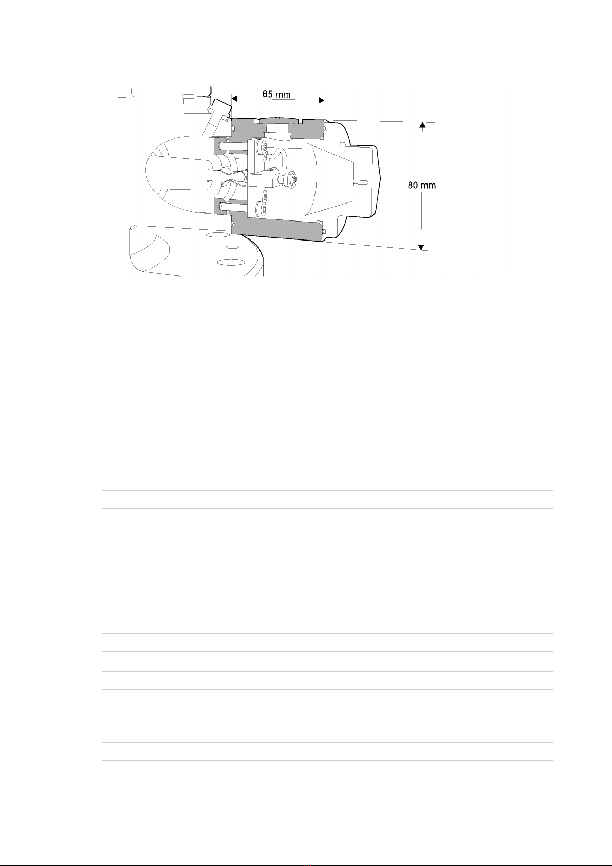
4.4.1 Removal of the lower draw rod with bottom contact from the bushing ..................................................................... 24
4.4.2 Installation of the small bottom contact (N1=4) in the transformer ............................................................................ 27
4.4.3 Installation of the large bottom contact (N1=6) in the transformer ............................................................................ 29
4.4.4 Installation of the bushing on the transformer ........................................................................................................... 31
4.4.5 Installation of the bushing with the fixed bottom contact ........................................................................................... 34
4.5 Installation at site......................................................................................................................................................................... 36
4.5.1 Preparations at site ................................................................................................................................................... 36
4.5.2 Installation of the bushing on the transformer at site................................................................................................. 39
4.5.3 Installation of the bushing with the fixed bottom contact ........................................................................................... 34
4.6 Hydraulic tightening of the draw-rod nut...................................................................................................................................... 45
4.7 Minimum oil-level in transformer ................................................................................................................................................. 49
4.8 Installation of the outer terminal .................................................................................................................................................. 49
4.9 Grounding of the bushing flange ................................................................................................................................................. 52

4Installation and commissioning guide
1ZSC000563-AAF EN, REV. 4, 2021-06-23
5 Commissioning 53
5.1 Waiting time before energization .................................................................................................................................................53
5.2 Recommended test before energization .....................................................................................................................................54
5.2.1 Overview ................................................................................................................................................................... 54
5.2.2 Tightness test between transformer and bushing flange........................................................................................... 54
5.2.3 Tightness test of bushing outer terminal.................................................................................................................... 54
5.2.4 Measurement of capacitance and dissipation factor ................................................................................................. 55
5.2.5 Measurement of through-resistance.......................................................................................................................... 58
6 Maintenance 59
6.1 Recommended maintenance ...................................................................................................................................................... 59
6.2 Checking the oil-level .................................................................................................................................................................. 61
6.3 Taking oil samples ....................................................................................................................................................................... 62
7 Re-packing 65
7.1 Removal of the bushing from the transformer, draw rod ............................................................................................................. 65
7.2 Removal of the bushing from the transformer, fixed bottom contact ...........................................................................................68
7.3 Re-packing of the bushing........................................................................................................................................................... 71
8 Spare parts and special tools 73
8.1 Summary ..................................................................................................................................................................................... 73
8.2 Spare parts .................................................................................................................................................................................. 73
8.3 Special tools ................................................................................................................................................................................ 75
9 Disposal and environmental information 79
9.1 Overview ..................................................................................................................................................................................... 79
9.2 Disposal and recycling ................................................................................................................................................................ 79
10 References 81
10.1 Summary ..................................................................................................................................................................................... 81
11 Appendix 83
11.1 Measurement record ................................................................................................................................................................... 83

Installation and commissioning guide
1ZSC000563-AAF EN, REV. 4, 2021-06-23
5
1 Safety
1.1 Levels of safety risks
Throughout the manual, various types of safety risks are indicated. The most serious level on this scale
provides a warning about serious personal injury or possible death, or major damage to a product, if the
instructions are not observed.
Symbols and their meanings
The following describes the symbols that appear in the manual, along with their meaning.
DANGER!
The yellow, filled warning triangle warns that an accident will occur if the instructions are not
complied with and that it will result in serious personal injury or death and/or major damage to the
product.
It is used, for example, to warn of such dangers as: contact with high voltage, explosion or fire
risk, risk for toxic gases, risk of crushing, impacts, falls from high places, etc.
CAUTION!
The round warning symbol warns that an accident could occur if the instructions are not observed,
and that this could result in personal injury and/or damage to the product.
It is also used to warn of risks that entail burns, eye or skin injuries, impaired hearing, crushing or
slipping injuries, tripping, impacts, falls from high places, etc.
In addition, it is used to warn of functional requirements when assembling or removing equipment
where there is a risk of damage to the product or downtime.
NOTE!
The comment symbol identifies important information and conditions. Also used to indicate any
danger that could lead to property damage.
Torque
The torque symbol indicates tightening torque.

6Installation and commissioning guide
1ZSC000563-AAF EN, REV. 4, 2021-06-23
1.2 Hazardous working situations
Hazard Action
Working close to high voltage. Disconnect all plant power. Ground all objects at the workplace.
If work must be done close to live plant components, make sure that
the safety distance is in compliance with the applicable safety
regulations.
Working on ladders and platforms. Work must be done in accordance with the applicable safety
regulations.
Do not use ladders or platforms in poor weather conditions.
Working with heavy objects. Do not walk under lifted objects.
Make sure that heavy objects are stable before starting work.
1.3 Safety precautions
Precaution Action
Transformer oil Collect used transformer oil in drums.
Transformer oil is dangerous. Fumes from hot oil can cause irritation
to the respiratory organs and the eyes. Long and repeated contact
with transformer oil can cause damage to your skin.
Waste and cleaning up Clean up liquid waste with an adsorbent. Treat waste as hazardous
to the environment.
Fire Extinguish fires with powder, foam or carbon dioxide.
1.4 Competence level
Installation of the bushing should only be performed by authorized personnel.
CAUTION!
Incorrect installation can lead to catastrophic failure of the transformer.

Installation and commissioning guide
1ZSC000563-AAF EN, REV. 4, 2021-06-23
7
2 Product description
2.1 Design
Overview
The GOE 2600 is a capacitance graded oil impregnated paper bushing made for immersed oil/air service.
General schematics
G006945
9 Oil plug
26 Oil-level gauge
36 Bottom contact
51 Oil sampling valve ½”
65 Mounting flange
68 Top housing
69 Porcelain insulator, air side
70 Test tap
71 Extension for current transformer
72 Porcelain insulator, oil side
74 Lifting eye Ø 70 mm

8Installation and commissioning guide
1ZSC000563-AAF EN, REV. 4, 2021-06-23
Terminal system
The bushing can be configured with one of two terminal systems: the fixed bottom contact system, or the
draw-rod system.
Terminal system Option
Draw-rod system Small bottom contact (N1=4)
Large bottom contact (N1=6)
Fixed bottom contact -
Draw-rod system
The draw rod can be configured with an optional joint (53) to fit transformers with short bushing turrets.
The bottom-contact joint (56) is locked with threadlocking fluid as standard.
The bushing has draw rod with two upper joints (52), they are always locked with threadlocking fluid. All
joints must be locked with threadlocking fluid when the bushing is in operation at site.
G006981
39 Lower joint (at flange level).
52 Upper joint.
53 Additional joint (option).
54 Thread is locked with threadlocking fluid.
55 Thread is NOT locked with threadlocking fluid.*
56 Bottom-contact joint, locked with threadlocking fluid. Unlocked as option.*
* All unlocked threads must be locked with threadlocking fluid, when the bushing is installed at site.
Fixed bottom contact
The fixed bottom contact is installed when it is delivered from Hitachi ABB Power Grids.
CAUTION!
Do not remove the six fixing bolts.

Installation and commissioning guide
1ZSC000563-AAF EN, REV. 4, 2021-06-23
9
G007609
36 Fixed bottom contact
Test tap
The bushing has a test tap that is connected to the outermost conductive layer of the condenser core. The test
tap is used to measure the bushing insulation by capacitance and dissipation factor. The cover connects the
outermost conductive layer to ground, and must always be installed when the bushing is energized.
The maximum one minute test voltage for this test tap is 20 kVrms. The test tap can be used as a power
source, if it is connected to an external capacitance. The operating voltage is limited to 6 kV.
CAUTION!
Do not energize the bushing without a test adapter or the cover installed. The bushing condenser
core is grounded through the cover to prevent damage to the bushing.
G006914
3 O-ring
57 Stud
58 Cover
59 Grounding spring

10 Installation and commissioning guide
1ZSC000563-AAF EN, REV. 4, 2021-06-23
Test adapter, 2769 522-C, optional equipment
The test adapter 2769 522-C is available for permanent connection to measuring circuits. Please refer to Test
adapter – Technical guide 1ZSC000563-ACS and Installation and maintenance guide 1ZSC000563-ACD.
G003049
2.2 Technical specifications
2.2.1 General specifications
Refer to the table for the standard technical specifications of the bushing. For conditions exceeding the
specifications, please contact Hitachi ABB Power Grids.
Application: Transformers
Classification: Transformer bushing
• Oil impregnated paper, capacitance graded, oil immersed.
• For outdoor use.
Ambient temperature limits: -40 °C to +40 °C, limit temperatures.
Maximum altitude of site: 1000 m
Level of rain and humidity: 1-2 mm rain/minute horizontally and vertically, according to
IEC 60060-1.
Maximum pollution level: According to the specific creepage distance, and IEC 60815.
Immersion medium: Transformer oil.
• Maximum daily mean oil temperature: +90 °C.
• Maximum temporary oil temperature, at short time
overload: +115 °C.
Oil-level in transformer: Not lower than 30 mm from the bushing flange.
Maximum pressure of medium: pg100 kPa (pg= relative to ambient pressure).
Angle of installation: Vertical
Test tap: Test tap with 8 mm male contact pin.
According to IEEE type A.
Conductor: Center-tube conductor.
Markings: Conforming to IEC.

Installation and commissioning guide
1ZSC000563-AAF EN, REV. 4, 2021-06-23
11
List of bushings applicable to this installation guide
Type Article number
GOE 2600 LF121085-D
GOE 2600 1ZSC902110-AAA
2.2.2 Mechanical loading
Maximum permitted static load on the outer terminal
The load must be applied below the midpoint of the outer terminal. The total cantilever load must be
perpendicular to the bushing axis. The bushing installation angle can be 0° – 30° from vertical.
NOTE!
The loads described in this section are static loads, for dynamic loads such as earthquakes and
extreme wheather conditions, please contact your Hitachi ABB Power Grids sales representative.
G006946
A. Maximum cantilever load at installation angle 0°
B. Maximum axial static load
C. Load applied at the midpoint
Type Test load 1 minute
(N)
Maximum cantilever load in operation
at installation angle (N)
Maximum axial
static load (N)
0° >0°
GOE 2600 9500 2500 On request. 20000
Maximum permitted torque on the outer terminal
The maximum torque that is permitted on the outer terminal is 250 Nm.

12 Installation and commissioning guide
1ZSC000563-AAF EN, REV. 4, 2021-06-23

Installation and commissioning guide
1ZSC000563-AAF EN, REV. 4, 2021-06-23
13
3 Delivery
3.1 Incoming inspection
• Make sure that all items have been delivered, refer to the packing list.
• Carefully inspect the bushings for shipping damage.
NOTE!
The bushing has been routine tested in oil, and there can be small quantities of oil remaining on
the oil-side of the bushing. Vaseline is used for lubrication of threads, and at some temperatures
Vaseline can appear as oil.
NOTE!
The oil-level is not shown correctly when the bushing is in the horizontal position.
3.2 Transportation
• The bushing must be transported in the transport box.
• The bushing must be transported in the horizontal position.
• Carefully inspect the bushing for damage after transportation.
3.3 Storage
Short term storage, less than 6 months
• The bushing can be stored outdoors, if it is in the transport box.
• Keep the transport box protected from water, when the bushing is stored outdoors.
• Keep the bushing dry, clean and protected against mechanical damage.
• The bushing can be stored in both the vertical, and horizontal positions.

14 Installation and commissioning guide
1ZSC000563-AAF EN, REV. 4, 2021-06-23
Long term storage, more than 6 months
• The bushing can be stored outdoors, if it is in the transport box.
Keep the transport box protected from water, when the bushing is stored outdoors.
• Keep the bushing dry, clean and protected against mechanical damage.
• Lift the bushing to the vertical position, and put it in a safe stand.
– As an alternative: keep the bushing in the transport box and lift it to an inclined position, with the
top end upwards and at an angle of at least 7°.
The bushing is delivered from Hitachi ABB Power Grids in a transport box, and the bushing is held in place
by support blocks in the box.
The transport box is marked with Top end, this identifies the end to lift when the bushing is in storage.
G006947
3.4 Lifting
3.4.1 Lifting the transport box
Overview
G006948
8 Soft lifting slings
43 Center of gravity

Installation and commissioning guide
1ZSC000563-AAF EN, REV. 4, 2021-06-23
15
Procedure
1. Make sure that the crane and the soft lifting slings are approved for the total weight of the transport
box and bushing. Refer to the weight in the packing list.
2. Attach soft lifting slings (8).
3. Make sure that the angle of the soft lifting sling is not more than 20°.
4. Carefully lift the transport box.
5. Set down the transport box on a flat surface.
End of instruction
3.4.2 Lifting the bushing out of the transport box
Overview
G006949
Procedure
1. Make sure that the cranes is approved for lifting the weight of the bushing. Refer to the net weight on
the packing list.
2. Open the transport box.
NOTE!
The cover is attached with screws.

16 Installation and commissioning guide
1ZSC000563-AAF EN, REV. 4, 2021-06-23
3. Remove the support blocks from the transport box and put them on the ground.
CAUTION!
Make sure that the ground is flat.
4. Install the lifting tool (88) on the flange.
G007208
5. Attach a soft lifting sling to the lifting tool (88) on
the lower part of the flange and then to the crane
hook.
G006950
6. Attach a soft lifting sling to the top part of the
porcelain insulator.
CAUTION!
Attach the soft lifting sling as close to
the top housing as possible, or damage
will occur.
G006951
7. Carefully lift the bushing.
8. Make sure that the support blocks are in the same positions as the support blocks in the
transport box.

Installation and commissioning guide
1ZSC000563-AAF EN, REV. 4, 2021-06-23
17
9. Lower the bushing onto the support blocks.
G006952
10. Remove the soft lifting sling at the top part of the porcelain insulator.
End of instruction

18 Installation and commissioning guide
1ZSC000563-AAF EN, REV. 4, 2021-06-23

Installation and commissioning guide
1ZSC000563-AAF EN, REV. 4, 2021-06-23
19
4 Installation
4.1 Tools
Tool Part number Note
Lifting tool PDV1909-1,-2,-4 -
Soft lifting slings - -
Pull-through cord 9760 669-A With M8 terminal.
For assembly and disassembly of the
draw rod.
Torque wrench key for hex socket
screws, 16 mm (M10) and 13 mm (M8),
torque 20 to 40 Nm.
- -
Wrench for hexagon head screws 45 mm
or adjustable wrench for 45 mm bolts
or larger.
- For the test tap cover.
Hydraulic jack 9769 897-A For removal, and installation of the
draw-rod system.
Box spanner 9760 669-B For removal, and installation of the
draw-rod system.
4.2 Consumables
Item Brand Hitachi ABB part
number
Note
Oil based Vaseline Fuchs - For treatment of contact surfaces. Does
not react with transformer oil.
Mobilgrease 28 MOBIL - Lubricates and protects metals against
corrosion. Protects rubber. Does not
react with transformer oil.
Molykote Multilub Dow Corning - For lubrication of draw-rod threads and
bolts on the outer terminal.
Thread-locking fluid
grade 42
- - High strength thread-locking fluid,
permanent locking.
Thread-locking activator
grade 47
- - Activator for thread-locking fluid
grade 42.

20 Installation and commissioning guide
1ZSC000563-AAF EN, REV. 4, 2021-06-23
4.3 Preparations
4.3.1 Installation of lifting tools
Overview
G006953
1 Lifting tool, PDV1909-1
85 Lifting yoke, PDV1909-4
1. Loosen the M8 bolts (24).
G004684
This manual suits for next models
2
Table of contents
Other ABB Industrial Equipment manuals
Popular Industrial Equipment manuals by other brands

ATOMSTACK
ATOMSTACK M4 manual

Branick
Branick 5130 Installation, Operation & Repair Parts Information

Schier
Schier GB-500 installation guide

MBO
MBO SVC 525C Translation of the original operating manual

Balluff
Balluff MICROPULSE+ BTL7-E501-M Series user guide

Bazell
Bazell Microseparator Transport, Installation and Initial Startup

QED
QED Shape Coil Operator's manual

Trinity Highway
Trinity Highway Yodock 2001MB Guide

Hiwin
Hiwin HT-L Series Assembly instructions

OETIKER
OETIKER FAST 3000 instruction manual

Siemens
Siemens FLENDER GHZP Assembly and operating instructions

Bakker Hydraulic Products
Bakker Hydraulic Products ROTAQ 55 manual