CSM ICG360 User manual

Note: This gyro is like no other - please read this manual fully before
installing and flying the gyro
To bring you a great gyro CSM simply threw away the rule book and started with a clean sheet. The result, the ICG360, is packed with
new concepts in gyro technology:-
•YawRateDemand
•FlightModes
•HeadingLock
•Built-inExponential
•Anti-driftTemperatureCalibration
•TwostagePowerSupplyregulation
•Flightmodetailoringvia(optional)PCinterfacecable/software
Introduction
If you are familiar with conventional tail rotor gyro systems it is important to understand how this gyro is
different in order to get the best out of it.
Conventional Gyro systems
In a conventional gyro the pilot applies a rudder command and, as the helicopter responds to the
command the gyro opposes the pilot's command. The yaw rate achieved in such a system depends on
the 'gain' of the gyro. The more gain the gyro has the lower the yaw rate that can be achieved. It is
common with such systems to have to reduce the gyro gain to achieve the required yaw rate for some
manoeuvres (this being accomplished with the gyro gain switch).
The ICG360
In designing the ICG360 we have adopted a 'Yaw Rate Demand' philosophy making the system a true
Yaw rate gyro. In this system the rudder command from the pilot is interpreted as a request to the gyro
to establish the desired yaw rate. The gyro drives the tail rotor servo as needed to obtain this yaw rate.
This means that the ICG360 makes full yaw rate available even at high gain settings. With this system
you can now use the rudder travel volume (ATV) and rudder rates facilities to set up the desired full-
stick yaw rate and the gyro gain switch now becomes a 'Flight Mode Switch' for the gyro. There is no
need for so called Pilot Authority Mixing - indeed you should not use pilot authority mixing with this gyro
Flight Modes
The ICG360 has two flight modes selectable by the transmitter gyro gain switch (or Auxiliary channel
switch). Note: A rotary knob or slider is not recommended as it is not possible to accurately and
repeatedly set the gain with these. The modes are:
Mode 0 (Standard Mode)
This mode gives flying characteristics that are similar to conventional systems.
Mode 1 (Heading Lock Mode)
This mode provides a much higher resistance to unwanted yawing movements than can be obtained
with a conventional gyro system. This mode has great advantages in the following situations:
1) For the beginner, where this mode makes it possible for him/her to almost ignore the tail rotor control
in the initial hovering phase, which is made even easier as this mode allows the tail trim to be set before
the helicopter leaves the ground. (see 'Trim Adjustment')
2) For cross-wind hovering manoeuvres where the natural tendency of the helicopter to weathercock into
wind needs to be resisted.
3) For backwards flight manoeuvres and general "3D" flying.
The Standard mode may be employed for basic forward flight where the natural tendency of the
helicopter to weathercock can be helpful, especially to the less experienced pilot.

The graph (Figure 1) shows the way in which the gyro gain channel provides both mode switching and
independent gain adjustment of the two modes. If the gyro gain channel pulse is longer than the centre
value (1.5ms) the gyro is in Standard mode while with the gain channel pulse shorter than 1.5ms the
gyro is in Heading Lock mode. The Travel Volume (ATV) settings for the two switch positions provide a
convenient way of adjusting the gyro gain for each mode from the transmitter. Increasing the ATV of the
gyro gain channel increases the gain for that mode. If it is being used with a basic radio system without
a suitable channel for controlling the gyro gain then the gyro will run as a single rate unit with gain
adjustable from the manual gain control on the unit itself. In this case the gyro defaults to the Standard
mode.
100%
1.5ms
0%
1ms 2ms
Flight Mode 0Flight Mode 1
Gain channel pulse length
Gain
(Standard Mode)(Heading Hold Mode)
Increasing gain Increasing gain
First Switch Position
Increasing gain channel ATV Increasing gain channel ATV
Second Switch Position
Gyro
Figure 1. The Gyro gain channel acts as both gyro mode switch and gain control
Installation.
Siting of the gyro.
Axis of rotation
(keep this parallel with main shaft of helicopter)
Attach to helicopter using two of the self-adhesive foam strips provided
COMPUTER
AUX. INPUT
REVERSE
SERVO
Rx 1-4 IN
Figure 2. Mounting the gyro
The ICG 360 should be mounted in the helicopter with its axis of rotation (as marked on the gyro case)
accurately parallel to the main shaft of the helicopter. The gyro sensor (together with the electronics of
the gyro) is anti-vibration mounted inside the gyro case. However, to provide further vibration and shock
resistance it is important that the gyro be mounted to the airframe using two of the double sided
adhesive foam strips provided. Do not use any other type of mounting foam as this will reduce the
performance of your gyro. Replacement strips are available as a CSM spare. The gyro case may be
aligned along or transverse to the length of the helicopter. For good adhesion, ensure that the surface to
which the gyro is attached is smooth, hard and clean. As with all high performance solid state gyro
systems, the ICG360 performs best if sited at a point of low vibration in the helicopter airframe. Where
possible avoid siting the gyro at the extreme front of the radio tray for example as this area is often
subject to high levels of main rotor generated vibration. Note: Tests suggest that the X-Cell plastic radio
tray may be too flexible and that better performance can be gained by mounting the gyro at the rear of
the frames.
Connecting to your radio system.
The ICG360 is designed to work with the following radio control systems:-
•FutabaPPM
•FutabaPCM1024
•JRPPM
•JRZPCM
•JRSPCM
If you wish to use this gyro with other types of radio system please contact CSM for advice.
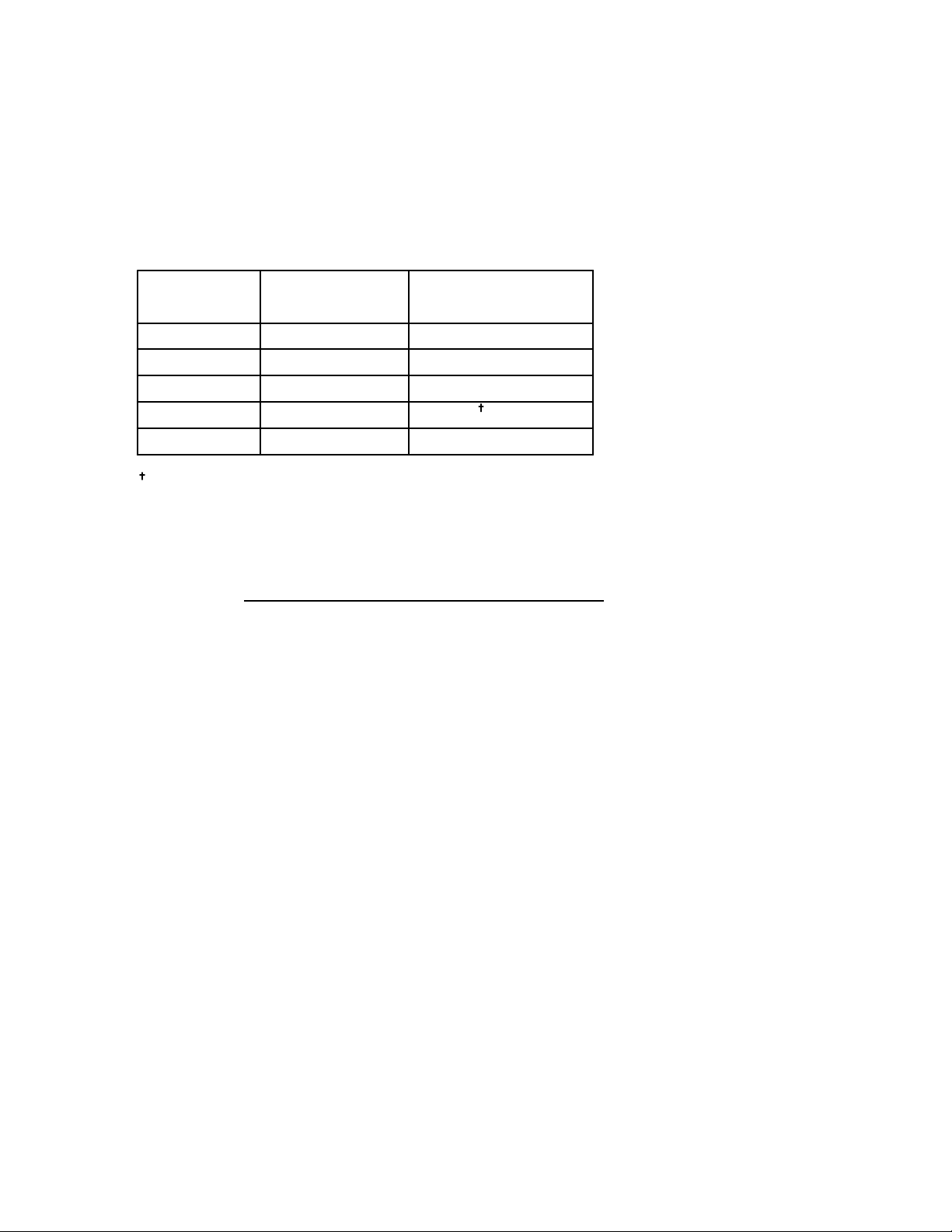
Connect the gyro to your receiver as indicated in the following table:-
Radio
Type
Gyro "Rx1-4 IN"
connect to
Gyro "AUX INPUT"
connect to
Futaba PPM
Futaba PCM
JR PPM
JR ZPCM
JR SPCM
Channel 4 Channel 5
Channel 4 Channel 5
"Rudd"
"Rudd"
"Rudd"
"Aux2" or "Aux3"
"Aux2"
"Aux2" or "Aux3"
JR ZPCM pulse timing prevents the use of Aux 3 as gyro gain channel
**
**
**
** See setup notes for JR X388/3810/8103
Connect the "SERVO" output to the tail rotor servo.
Leave the "COMPUTER" connector unconnected. (This is for use with the optional PC interface
cable/software). Do not connect any form of extension to this connector.
If you are using a radio system (e.g. a 4 channel aero set) that does not have a channel that can be
allocated to the gyro gain/mode then the "Aux" input to the gyro should be left unconnected. In this case
the gyro will default to the Standard mode with the gain adjusted by the rotary gain control (near to the
"gyro set" light on the front panel of the gyro). Initially set the gain control to its mid position. Final
adjustment will require flight testing.
Futaba 9ZHP/ZAP
On these transmitters it is important to ensure that in all flight modes the gyro sense mode is set to
INHIBIT (see the "GYR" entry of the "helicopter condition" menu). Check under the "PMX" entry that no
throttle to rudder or rudder to gyro mixing is active in any of the flight conditions. Check in the "P->R"
entry that pitch to rudder mixing is inhibited. Under the "model" menu use the "FNC" entry to allocate
the gyro control to a switch of your choice.
JR PCM10S/SX
On these radios it is easier to disable the JR 'code 44' (gyro sense adjust) and control the gyro gain by a
switch, but if the ability to automatically switch between both gyro modes by the use of the flight mode
switch (idle up) is required, then the JR gyro sensing (code 44) should be used. Because the ICG360
gain control works from the centre of the channel outwards, an LCD value of 50% (the channel centre) is
in reality zero gain. Increasing the value will increase the gain in one flight mode, the other mode is
adjusted by decreasing the value below 50%: be aware that this value will be reversed so that an LCD
value of 25% will actually be a higher gain value than a LCD value of 30%. Note: if the gyro is adjusted
through the JR gyro software, the gyro channel ATV's/TA should be set to default values (100%).
JR X388S/X3810/X8103
On these radios it is easier to control the gyro gain through the gear channel as it is not always possible
to have control over other channels on a 2 position switch. Note: if so desired it is possible to set the
gyro up using the JR gyro software on the 3810/8103, see the PCM10 instructions above.
Reversing link
As with any gyro it is vital to ensure that it operates in the correct sense. Failure to do this will cause
an uncontrollable pirouette on take-off and beginners who are in any doubt on this aspect of the

set-up should seek advice. First establish that the sense of the transmitter control is correct (i.e. that
the application of a right rudder command causes a change in tail pitch that will rotate the helicopter to
the right). Once this has been done check that turning the helicopter to the left makes the gyro apply a
tail rotor command to the right. Should the gyro operate in the wrong sense use the gyro "REVERSE"
link to correct it. The gyro is supplied with the reversing link already fitted and to remove it simply pull
on its protruding tab and store it safely. When replacing the reversing link ensure that it is fitted over
both pins and pushed firmly into full engagement.
Initial Radio set-up
For initial flights we suggest that you adjust the radio system as follows:
ATS (Automatic Tail Stabilisation): OFF
Pilot Authority Mixing: OFF (this should never be used with the ICG360)
Rudder channel ATV (both directions): 50%
Gyro gain channel ATV (both directions): 50%
Mechanical
The ICG360 will work with any servo in the Futaba or JR ranges but as with any gyro system a fast
servo (e.g. Futaba FP-S9203 or JR 2700G) will give the best results.
To prevent damage due to excessive servo travel the servo movement is limited by the gyro
electronics. (Under no conditions will the servo travel past the electronic limit set by the gyro, regardless
of any increase in the ATV value.) You should use the longest servo arm that gives full movement of
the tail rotor pitch linkage without causing the linkage to bind or the servo to become stalled at
either extreme of travel.
Attention to the tail control linkage is important to getting the best from this gyro. You should aim for a
easy-moving but slop-free linkage between the tail servo and the tail blades. Inspect the bearings/thrust
races in the tail hub for smoothness of operation. Check the pitch slider and ball links for slop and
replace if needed. Some helicopters that have noticeable 'give' in the tail linkage may benefit from the
addition of a rear-mounted tail servo and rigid pushrod.
Remember that, during aerobatic manoeuvres, the combination of a high performance gyro and a fast
tail servo can place very high loads on the tail rotor drive train. Regularly Inspect tail rotor gears, etc. to
ensure that they are in good condition.
Batteries, power consumption, and wiring
Although the power consumption of the gyro unit itself is very modest, as with all high performance Solid
State gyro systems the speed of the gyro response will work the tail rotor servo harder than slower
mechanical gyro systems. Especially where a high performance servo is being used the battery drain
from the tail rotor servo can be high. We recommend that you use a good quality battery state
monitor and check it carefully before each flight.
Your receiver battery is a vital part of your tail rotor system. Remember that a battery in a low state of
charge or an old battery which has developed a high internal resistance will adversely affect servo
performance and may even cause the tail to wag on an otherwise well set up helicopter. You may wish
to consider maintaining the charge in your receiver battery between flights by the use of a quality Delta
Peak type field charger. In installing the gyro also bear in mind that voltage drops down long servo
extension leads will also detract from servo performance. Where the installation requires extensions to
be used (either between the receiver and gyro or between the gyro and the servo) avoid using ones that
are unnecessarily long.
Trim adjustment
Initially zero the rudder trim and any rudder sub-trim that your transmitter may have. Next, identify which
gyro gain switch position gives you Standard mode and which gives you Heading Lock mode. This can
be seen from the difference in the tail rotor servo behaviour on the ground. In Standard mode the rudder
servo will return to the neutral position when any rudder command is released, while in heading lock
mode the servo will tend to remain at or near its travel limit when a full stick rudder command is applied
and then removed. Now set the rudder trim so that with the gyro in Heading Lock mode the servo, once
centred, has no marked tendency to creep in either direction (though some slow residual creep of the
servo is quite normal). Once this trim position has been found no further adjustment of the transmitter
trim should be needed. However, slight adjustment of the helicopter tail control linkage may be needed
in order to remove any offsets in the Standard mode. This can only be done by flight trials.

Behaviour on the ground
For those used to conventional gyro systems the behaviour of the ICG360 on the ground may seem
unusual.
Unlike conventional systems, it is quite normal for the ICG360 in Standard mode to provide full tail rotor
servo movement for rudder commands that are as little as 30% of the full stick movement. This is a
consequence of the Yaw rate demand feature.
With the helicopter on the ground and the ICG 360 set in Heading Lock mode it is quite normal for the
tail rotor servo to slowly creep and may over the course of say 15 seconds creep to full travel. Your
transmitter rudder trim will affect the direction and speed of this creep but even after the trim has been
adjusted to minimise this some slow movement is still to be expected. This apparently strange
behaviour is caused by the stationary helicopter not responding to the heading corrections requested by
the gyro. In the absence of a response from the helicopter the gyro continues to increase the servo
command in an attempt to get the helicopter to obey. In flight the helicopter will, of course, respond to
the tail servo movements and the system act normally.
Trouble shooting
If the gyro does not respond as expected to any adjustment of the ATV, it may be helpful to plug a spare
servo directly into the appropriate RX channel as a check to make sure that the radio is driving the
channel as required, and that no other switches, mixers or other functions are interfering with the
operation of the channel.
Flying the gyro
Turn-on sequence
1. Turn on your transmitter
2. With the model stationary on the ground turn on your receiver.
3. Wait for about 7.5 seconds keeping the model still while the gyro goes through its self test.
4. Observe that the gyro set light comes on (or if this is inaccessible in your model move the rudder stick
full travel in both directions and ensure that the tail rotor servo responds to the stick movements)
5. Your ICG360 is now ready for flight.
If the set light fails to come on or flashes turn off the receiver for a few seconds and repeat the turn on
sequence.
!! Make sure the model is not moved during the gyro self test period. !!
Initial flight trials and setting up.
First select flight mode 1 (Heading hold mode) and hover the helicopter. Use short small 'stabs' of
rudder control to disturb the helicopter in yaw and observe. If some tendency to oscillate is seen, slightly
reduce the gyro gain. Conversely if no tendency to oscillate is seen try increasing the gain. You are
looking at this stage for the highest gain that gives no sign of oscillation when the tail is disturbed by
sudden changes in tail command. Observe any trim offset in the tail and correct this with the transmitter
rudder trim.
Now switch to Flight mode 0 (Standard mode) and repeat the exercise but in this case any trim offset
should be removed not by use of the transmitter trims but by adjusting the tail rotor linkage.
Once this has been done you may wish to check for tail wagging in fast forward flight. Should this be
observed, you may wish to lower the gyro gain slightly. Caution should be exercised over the use of the
heading hold mode in flying circuits or other general flying until you are familiar with the very special
handling characteristics this mode gives.
Adjusting the stick response
After initial setting use the rudder ATV, Rates, and Exponential facilities of the transmitter to tailor the
control response as required. Beware that the maximum yaw rate available (at any gain) is very
high. If an increase in available yaw rate is required increase the rudder travel on your transmitter
gradually until the desired response is obtained. Remember that increasing the ATV/TA will not
increase the overall tail throw.
The ICG360 has built-in exponential. You may find the following graph of yaw rate against rudder
command useful in deciding on the setting of rudder rates and rudder ATV. Remember that the ATV and

rates facilities work together so that setting the rudder ATV to 80% in both directions and also setting a
rudder rate of 60% will give a total rudder throw of 0.8 x 0.6 = 0.48 = 48%
100%20% 40% 60% 80%
200
400
600
800
1000
1200
1400
1600
Rotation rate (Deg./s)
Rudder signal (as % of standard 1 to 2ms deviation)
Figure 3. The built-in Exponential of the ICG360 gives this response to rudder control
Automatic Tail Stabilisation (ATS)
In Heading Lock mode the ICG360 requires NO ATS. Use of ATS in this mode will give unwanted
heading changes. Similarly, no Throttle-to-Tail Rotor mixing should be used in this mode. In Standard
mode you may find very small amounts of ATS or Throttle-to-Tail Rotor mixing useful.
Pilot Authority Mixing
This should not be used with the ICG360 gyro.
Tail rotor dynamics
To realise the full benefit of the ICG360 it is important to have a basic understanding of the dynamics of
the tail rotor system. It is a common misbelief that the higher the electronic gyro gain is, the better the
system will work. Whilst this is generally true, the electronic gain is only one part of the tail rotor system
and of equal importance is the amount of tail pitch range available, and the tail rotor disk size. The disk
size is also related to the tail rotor speed. Of course there are other influences on the tail system but
these are the most important and can be grouped together as mechanical gain.
If the mechanical gain is not correct, then the gyro will not be able to function to its best ability. For this
reason it is important to select the correct size servo arm that will give maximum tail pitch movement
without stalling the servo. Note: once this has been setup, increasing the rudder channel ATV/TA will not
increase the servo throw as this is limited electronically by the gyro. The rudder ATV/TA is used instead
to adjust the rotation rate.
Tail blade size
The correct length of tail blade can only be selected by flight testing. There are 2 types of test to
ascertain the correct size:
1) With the model in the hover at its normal flight rpm, making sure the gyro is in heading hold mode,
make a rapid vertical climb for 50 to 60 feet: there should be no discernible rotation of the model. If the
tail does not maintain its position this is a good indication that the diameter is too small. Note: if the
model is over pitched and there is a noticeable drop in rotor rpm during the climbout, then this will
invalidate the test as the tail would probably not be able to cope with this situation regardless of the
setup.

2) This test is only really necessary for those who wish to do advanced aerobatics/3D flying and should
only be carried out those who are confident to do so. With the model at a safe height fly the model
sideways, starting slowly and building up speed until it reaches its maximum possible speed:
a)If the tail manages to hold its position then the blade length is OK.
b)If the tail starts to lag behind, then either more pitch is needed (if the mechanical limits haven't
already been reached) or longer tail blades.
c) If the tail swings round suddenly and cannot return to the correct position then the tail rotor is stalling
and longer tail blades are needed.
Maximising Performance for Advanced 3D/Aerobatic Flight - by Bob Johnston
To get the maximum performance from this or any piezo gyro it is essential to minimise the vibration
reaching the gyro sensor. Apart from the obvious balance checks, make sure that the canopy, fins,
tuned pipe or muffler are not too loosely mounted, especially if the gyro is being used with a fast servo,
as it is possible for a resonance to build up which shows as a very fast shake, visible in the canopy and
tail.
If you feel confident to do so, try slowly tumbling the model while checking for any visible vibration, a
small amount is almost inevitable, but try to dampen any large vibrations present. Alternatively tumble
or roll the model at a safe height and if the gyro can be made to wag through the manoeuvre this is a
good indication that a component is resonating.
To set the maximum gain permissable for aerobatic flight, either a) fly the model as fast as possible in
a straight line and twitch the rudder stick a small amount, if this causes the gyro to wag, lower the gain
and repeat the test until the tail cannot be made to wag anymore. Obviously if the model cannot be
made to wag initially, keep increasing the gain until it does, and then reduce the gain a few percent.
Setting the gyro this way should prove sufficient for all flying except in very windy turbulent conditions
where the gain may have to be lowered by a few percent. b) Alternatively, if you feel confident enough
in your ability and your models reliability, put the model in a vertical dive for 3 or 4 hundred feet (90 to
120 metres) with the main rotor pitch at zero. Once terminal velocity has been reached, pull the model
out in a smooth arc, and if the model does not wag under these conditions it is unlikely to do so under
any conditions.
WARNING: Only attempt to carry out these flight tests if you are 100% confident in your own
flying ability, and the structural integrity of your equipment.
Boom supports
Tests have shown that the use of boom supports significantly increase the rigidity of the tail boom and
so allow a higher gyro gain to be used. Generally the longer the boom supports the better they will work.
Note: A loose/cracked boom support or a loose/cracked boom support clamp can have a significant
effect on the gyro gain.
Temperature stability
Although the gyro is temperature calibrated small temperature differences between the piezo sensor and
the temperature sensor occur from internal heating of the piezo sensor. These may cause a small trim
change during the first two minutes of operation. It is best to avoid flying the model immediately after
exposure to sudden temperature changes such as removing it from a cool car to a very hot flying site.
Humidity
Under conditions of extremely high humidity it is possible for condensation to form on the piezo sensor.
Formation and evaporation of this condensation will cause a shift in the gyro trim. Where it is not
possible to avoid subjecting to the gyro to such humidity levels it is advisable to leave the model
standing for a few minutes with the radio switched on so that the internal heating of the sensor disperses
the condensation. Having done so, cycle the receiver power to reset the gyro. Always protect the gyro
from ingress of water (e.g. rain).
PC interfacing
Your ICG360 is equipped with a 'COMPUTER' port which is provided for the experienced pilot wishing to
optimise the internal settings of the ICG360's two flight modes to their helicopter and flying style. An
optional Interface cable and software disk is available for use with this port. The interface/software is
compatible with any IBM PC compatible with a parallel (printer) port and VGA graphics. Comprehensive
additional instructions on the use of the PC interface are supplied with the software. Connection to the
'COMPUTER' port of the ICG360 must only be made via the correct optional interface cable.
No other form of connection to this port should be made as mis-use of this facility may damage the gyro
unit.

Ratings
Weight: 40g
Dimensions : 42.5mm High x 26.5mm Wide x 46.5mm Long
(excluding cables and mounting ears)
Power Supply: 3.5 to 7.2v
Repairs & Servicing
For repairs and servicing only, please contact:-
Westbury Products
Armour House
Brunswick Square
Southampton
Hants
SO14 1AR (Fax 01 703 335 463)
Manufactured in the UK by:
CSMDesignConsultancyLtd
8LittlebrookClose
Hadfield
Hyde
Cheshire
SK148AW(Fax:01619295984)
Distributed world-wide by:-
J.Perkins(Distribution)Ltd
90-96GreenwichHighRoad
LondonSE108JE
(Tel:01816922451
Fax:01816922469)
DOs and DON'Ts
DOs:
Do mount the gyro with its axis of rotation parallel to the helicopter main shaft.
Do mount the gyro on two of the supplied self-adhesive foam strips.
Do mount the gyro to a hard, smooth clean surface.
Do use the rudder ATV and rates to tailor required stick response.
Do check the sense of the gyro operation and fit/remove Reversing link as needed before flight.
Do use a battery state monitor and check it before each flight.
Do remove slop and stiffness from tail control linkage.
Do inspect tail gears etc. for wear.
Do explore the performance limits of this gyro with care.
DON'Ts:
Don't mount the gyro where it will be subjected to high vibration levels.
Don't use Pilot Authority Mixing.
Don't use ATS or Throttle-Tail mixing with the Heading Lock mode.
Don't use unnecessarily long servo extension leads with the gyro.
Don't use Aux3 as gain channel with JR ZPCM receivers
Don't connect a servo extension to the "COMPUTER" port of the gyro.
Don't move the model during gyro self-test time.
Table of contents
Other CSM Accessories manuals


