Maxcess FIFE DSE-15 User manual

FIFE GUIDING SOLUTIONS
FIFE DSE-15
Operating Instructions
Reflected light sensor
MI 1094 1
EN

ICONTENTS
DSE-15 www.maxcess.euMI 1094 1
INTRODUCTION 1-1
About these operating instructions . . . . . . . . . . . . . . . . . . . . . . . . . . . . . . . . . . . . . . . . 1-1
Target groups . . . . . . . . . . . . . . . . . . . . . . . . . . . . . . . . . . . . . . . . . . . . . . . . . . . . 1-1
Proper usage . . . . . . . . . . . . . . . . . . . . . . . . . . . . . . . . . . . . . . . . . . . . . . . . . . . . . . . . . 1-1
Improper usage . . . . . . . . . . . . . . . . . . . . . . . . . . . . . . . . . . . . . . . . . . . . . . . . . . . . . . . 1-2
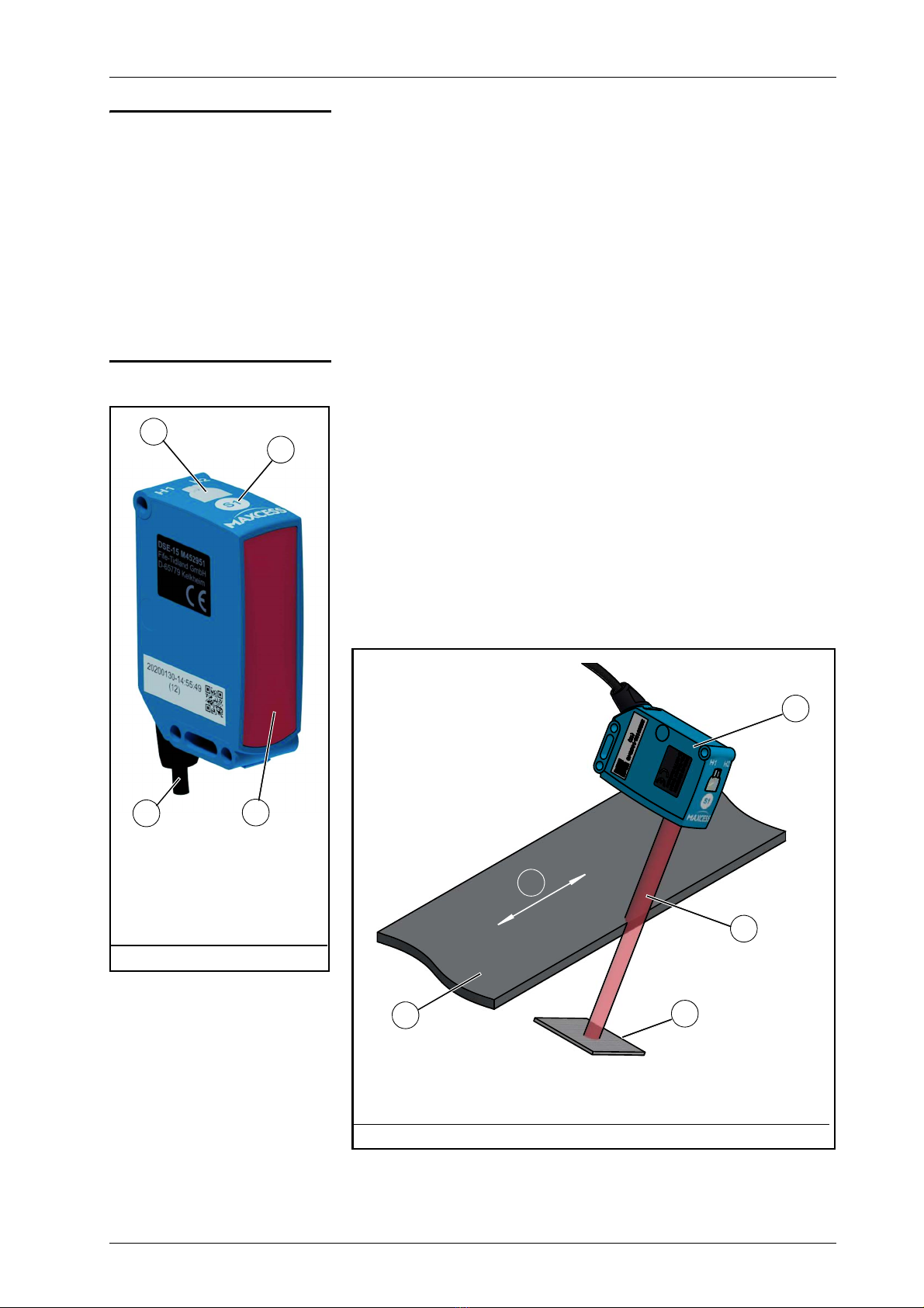
Operating principle . . . . . . . . . . . . . . . . . . . . . . . . . . . . . . . . . . . . . . . . . . . . . . . . . . . . 1-2
Option . . . . . . . . . . . . . . . . . . . . . . . . . . . . . . . . . . . . . . . . . . . . . . . . . . . . . . . . . . 1-3
SAFETY INSTRUCTIONS 2-1
Important information . . . . . . . . . . . . . . . . . . . . . . . . . . . . . . . . . . . . . . . . . . . . . . . . . . 2-1
Information about safety instructions . . . . . . . . . . . . . . . . . . . . . . . . . . . . . . . . . . . . . . 2-1
Signal words . . . . . . . . . . . . . . . . . . . . . . . . . . . . . . . . . . . . . . . . . . . . . . . . . . . . . . 2-1
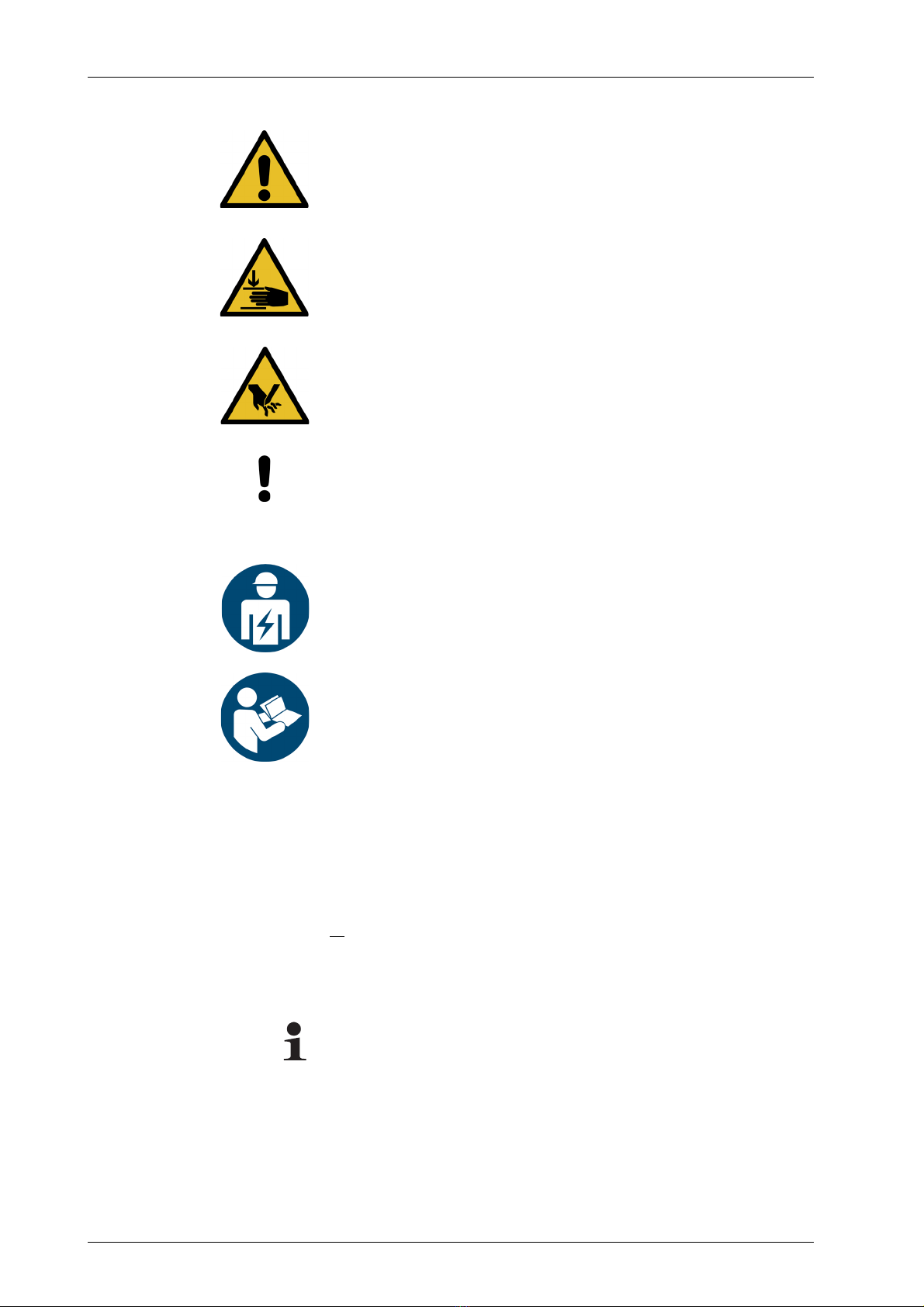
Symbols . . . . . . . . . . . . . . . . . . . . . . . . . . . . . . . . . . . . . . . . . . . . . . . . . . . . . . . . . 2-2
Additional markings . . . . . . . . . . . . . . . . . . . . . . . . . . . . . . . . . . . . . . . . . . . . . . . . 2-2
Personnel requirements . . . . . . . . . . . . . . . . . . . . . . . . . . . . . . . . . . . . . . . . . . . . . . . . 2-3
Qualified electrician . . . . . . . . . . . . . . . . . . . . . . . . . . . . . . . . . . . . . . . . . . . . . . . . 2-3
Preventing hazards . . . . . . . . . . . . . . . . . . . . . . . . . . . . . . . . . . . . . . . . . . . . . . . . . . . . 2-4
Residual risks . . . . . . . . . . . . . . . . . . . . . . . . . . . . . . . . . . . . . . . . . . . . . . . . . . . . . . . . 2-4
INSTALLATION 3-1
Transport and storage . . . . . . . . . . . . . . . . . . . . . . . . . . . . . . . . . . . . . . . . . . . . . . . . . . 3-1
Included with delivery . . . . . . . . . . . . . . . . . . . . . . . . . . . . . . . . . . . . . . . . . . . . . . . . . . 3-1
Mounting . . . . . . . . . . . . . . . . . . . . . . . . . . . . . . . . . . . . . . . . . . . . . . . . . . . . . . . . . . . 3-1
Mounting location . . . . . . . . . . . . . . . . . . . . . . . . . . . . . . . . . . . . . . . . . . . . . . . . . 3-2
Dimensions . . . . . . . . . . . . . . . . . . . . . . . . . . . . . . . . . . . . . . . . . . . . . . . . . . . . . . 3-2
Mechanical fastening . . . . . . . . . . . . . . . . . . . . . . . . . . . . . . . . . . . . . . . . . . . . . . . 3-2
Distance between reflector and sensor . . . . . . . . . . . . . . . . . . . . . . . . . . . . . . . . . . 3-5
Alignment of reflector and sensor . . . . . . . . . . . . . . . . . . . . . . . . . . . . . . . . . . . . . 3-6
Electrical connection . . . . . . . . . . . . . . . . . . . . . . . . . . . . . . . . . . . . . . . . . . . . . . . . . . . 3-8
CONTROL ELEMENTS 4-1
COMMISSIONING 5-1
Setting up the sensor and reflector . . . . . . . . . . . . . . . . . . . . . . . . . . . . . . . . . . . . . . . . 5-1
Setup . . . . . . . . . . . . . . . . . . . . . . . . . . . . . . . . . . . . . . . . . . . . . . . . . . . . . . . . . . . 5-1
Calibrating the sensor inputs of the web guide controller . . . . . . . . . . . . . . . . . . . . . . . 5-2
OPERATION 6-1
Operation . . . . . . . . . . . . . . . . . . . . . . . . . . . . . . . . . . . . . . . . . . . . . . . . . . . . . . . . . . . 6-1
LEDs in normal operation . . . . . . . . . . . . . . . . . . . . . . . . . . . . . . . . . . . . . . . . . . . . . . . 6-1
MAINTENANCE 7-1
Maintenance . . . . . . . . . . . . . . . . . . . . . . . . . . . . . . . . . . . . . . . . . . . . . . . . . . . . . . . . . 7-1
Cleaning . . . . . . . . . . . . . . . . . . . . . . . . . . . . . . . . . . . . . . . . . . . . . . . . . . . . . . . . . 7-1
Setting up the sensor again . . . . . . . . . . . . . . . . . . . . . . . . . . . . . . . . . . . . . . . . . . 7-1
Maintenance . . . . . . . . . . . . . . . . . . . . . . . . . . . . . . . . . . . . . . . . . . . . . . . . . . . . . . 7-1
Decommissioning . . . . . . . . . . . . . . . . . . . . . . . . . . . . . . . . . . . . . . . . . . . . . . . . . . . . . 7-2
TROUBLESHOOTING 8-1
LED display . . . . . . . . . . . . . . . . . . . . . . . . . . . . . . . . . . . . . . . . . . . . . . . . . . . . . . . . . . 8-1
Fault . . . . . . . . . . . . . . . . . . . . . . . . . . . . . . . . . . . . . . . . . . . . . . . . . . . . . . . . . . . . . . . 8-1
TECHNICAL DATA 9-1
General information . . . . . . . . . . . . . . . . . . . . . . . . . . . . . . . . . . . . . . . . . . . . . . . . . . . 9-1

IICONTENTS
DSE-15www.maxcess.eu MI 1094 1
MI10941-IVZ.fm
Properties . . . . . . . . . . . . . . . . . . . . . . . . . . . . . . . . . . . . . . . . . . . . . . . . . . . . . . . . . . . 9-1
Electrical connection . . . . . . . . . . . . . . . . . . . . . . . . . . . . . . . . . . . . . . . . . . . . . . . . . . . 9-2
Pin assignment . . . . . . . . . . . . . . . . . . . . . . . . . . . . . . . . . . . . . . . . . . . . . . . . . . . 9-2
Standards . . . . . . . . . . . . . . . . . . . . . . . . . . . . . . . . . . . . . . . . . . . . . . . . . . . . . . . . . . . 9-2
SERVICE 10-1
Requests for Service . . . . . . . . . . . . . . . . . . . . . . . . . . . . . . . . . . . . . . . . . . . . . . . . . . 10-1
Adresses . . . . . . . . . . . . . . . . . . . . . . . . . . . . . . . . . . . . . . . . . . . . . . . . . . . . . . . . . . 10-1

INTRODUCTION1 - 1
DSE-15 www.maxcess.euMI 1094 1
1 INTRODUCTION
About these operating
instructions These Operating Instructions describe the installation,
operation, commissioning, and maintenance of the DSE-15
sensor and provide important instructions for proper use.
The operating instructions must be carefully stored and must
always be available at or near the customer's system during the
service life of the sensor.
Translation of the original Operating Instructions:
These Operating Instructions are a translation. The original
Operating Instructions were composed in German.
Target groups These Operating Instructions are directed to both the
system
construction
master
as well as the
operator
who uses the sensor
in production line.
Read operating instructions
The Operating Instructions must be read and used by
all persons
who have the responsibility of installing, commissioning,
operating and maintaining the sensor.
Proper usage The digital reflected light sensor D
SE-15
is used for non-
contact measurement of the lateral offset of a material web
being guided in a customer system. The sensor is suitable for
– Web edge guiding and
– Web center guiding for dual application.
The sensor can be used to control opaque , transparent or
reflective materials.
The sensor must only be used in accordance with its intended
purpose and in a technically flawless conditions.
The sensor must not be changed or opened.

INTRODUCTION 1 - 2
DSE-15www.maxcess.eu MI 1094 1
Einführung.fm
Improper usage – Operation outside of the technical specifications is not
permitted.
– Operation in areas where there is a danger of explosions is
prohibited.
– The sensor may not be used as a support, handle or step.
– Any use other than the designated use is not permitted.
Operating principle The DSE-15 sensor uses pulsing, visible red light for coaxially
transmitted and received light beams. This makes the sensor
insensitive to ambient light and reflections.
The light source generates a red light. Depending on the
amount of the sensor field of view covered by the material web,
a portion of the light strikes the reflector installed under the
material web. Reflected light is received by the sensor and the
ambient light is filtered out. Based on this the receiver generates
the output signal from which the precise position of the web
edge is determined.
1Protector
covers the light source and
receiver
2 Capacitive key
3LEDs
4 Connection cable
Figure 1.1: DSE-15 sensor
3
1
2
4
1 DSE-15 sensor
2 Red light beam
3 Reflector
4-Materialweb
5-Webguidedirection
Figure 1.2: Operating principle
3
4
2
5
1

INTRODUCTION1 - 3
DSE-15 www.maxcess.euMI 1094 1
It is possible to operate the sensor with either a supply voltage
of 12V or 24V. The output signal would automatically be
switched over in that case.
– Power supply voltage 12V:
The sensor provides an output signal in the range from 0 to
10mA. Thus the sensor can be connected to all Fife web
guide controllers.
– Power supply voltage 24V:
The sensor provides an output signal in the range from 4 to
20mA. This can be used to establish a wire-break-proof
connection to external devices.
An integrated LED display shows information about operation
states directly on the sensor, for example whether supply
voltage is applied, the cover of the red light beam and error
messages.
Option A digital production data acquisition to Fife D-MAXE controller
extends the range of applications for the sensor inside the
digital network environment. Additional sensor data can be
provided to other hardware equipment if the Fife D-MAXE is
linked appropriately to the network.

SAFETY INSTRUCTIONS 2 - 1
DSE-15www.maxcess.eu MI 1094 1
Sicherheit.fm
2 SAFETY INSTRUCTIONS
Important information To ensure safe and problem-free operation of the DSE-15
sensor it must be
– properly shipped and stored,
– properly mounted and placed in operation,
– properly used and carefully maintained.
Proper operation and careful maintenance will ensure a long
service life for the sensor.
Please note the following:
– The content of these operating instructions
– Any safety instructions that are printed on the unit
– The requirements of the machine manufacturer
– Applicable national, state and local requirements for accident
prevention and environmental protection
Information about
safety instructions The safety instructions and symbols described in this section
are used in these Operating instructions. They are used to avoid
possible dangers for users and to prevent material damage.
SIGNAL WORD
Source of danger and its results.
Avoiding dangers
Signal words The signal word DANGER indicates an immediate danger of
serious injury or death.
The signal word WARNING indicates a possible danger which
could lead to serious injury or death.
The signal word CAUTION refers to a possible danger which
could lead to slight to moderate injury.
The signal word ATTENTION refers to a possible danger which
could lead to material damage.

SAFETY INSTRUCTIONS2 - 2
DSE-15 www.maxcess.euMI 1094 1
Symbols
Reference to general hazards that may result in bodily injuries
Refers to danger of injury caused by crushing
Refers to danger of injury caused by cutting
Refers to general hazards that will result in damage to the
device or system
Qualified electrician
The electrical components may only be connected and
disconnected by a qualified electrician!
Read operating instructions
Follow these operating instructions for proper and safe use.
Keep for future use.
Additional markings – Bulleted list
∙Instructions
1. Instructions which must be processed in the specified order
2. End of the instructions
Reference or cross-reference
Note:
Reference to important information.

SAFETY INSTRUCTIONS 2 - 3
DSE-15www.maxcess.eu MI 1094 1
Sicherheit.fm
Personnel requirements The tasks listed in these operating instructions may only be
carried out by appropriately qualified personnel commissioned
by the operator. The responsibilities of the personnel for the
work on the system must be clearly defined by the operator.
Transport, assembly, maintenance, troubleshooting,
disassembly:
– Specialized staff
Mechatronics engineer, industrial mechanic, etc.
Electrical connection or disconnection:
– Specialized staff
Only by a qualified electrician
Control during operation:
– Specialized staff
Machine and system operators, etc.
– Personnel or trainees trained and supervised by the system
operator
Repair:
– Specialized staff
Service technician of Fife-Tidland GmbH
Qualified electrician
A qualified electrician is a person whose specialist training,
knowledge and experience, as well as knowledge of the relevant
standards, enable him to assess and perform the work assigned
to him and to recognize and avoid possible hazards.
The electrician is specially trained for the field in which he or
she works and is familiar with the relevant standards and
regulations.

SAFETY INSTRUCTIONS2 - 4
DSE-15 www.maxcess.euMI 1094 1
Preventing hazards – No changes may be made to the sensor.
– The parameters specified in Section
Technical Data
must be
observed.
– Only accessories and replacement parts that have been
approved by Fife Tidland may be used.
– The sensor may not be used as a support, handle or step.
There is a danger that the sensor will become damaged
(breaking off/snapping), resulting in personal injury.
Residual risks Installing the product in a machine/system makes it possible to
form clamping, squeezing and cutting points.
Despite a safe design and supplementary protective measures,
residual risks may remain for the machine/system in which the
product is installed. These risks must be recorded in a risk
assessment by the machine/system builder and taken into
consideration in the operating instructions.

INSTALLATION 3 - 1
DSE-15www.maxcess.eu MI 1094 1
Installation.fm
3 INSTALLATION
Transport and storage – The sensor and/or the unit on which the sensor is mounted
must be secured against slipping during transport
– The sensor must be stored in a cool, clean, and dry place.
Ambient conditions, page 9-1
– The sensor must not be stored in the vicinity of powerful
magnetic fields. The electronic components of the sensor
may be damaged.
Included with delivery – Reflected light sensor DSE-15
The model designation and part number are on the
nameplate on the housing.
– Mounting bracket and fastening material
–Reflector
– Operating instructions
Mounting
WARNING
If a sensor is damaged, it must not be installed or placed in
operation.
All assembly tasks on the sensor must only be performed
when there is no electrical power in the system.
Assembly tasks and mechanical settings must only be
performed when the machine has been stopped and secured
from being turned on again.

INSTALLATION3 - 2
DSE-15 www.maxcess.euMI 1094 1
Mounting location –ProtectionClass:IP65
– Operating temperature: 5°C ... 60°C
– Relative humidity: max. 90%, non-condensing
– Operating altitude above sea level: maximum 3000m
– Protected from vibrations
– Do not place close to strong magnetic fields:
The electronic components may be damaged.
– Do not place close to strong electrostatic fields:
The electronic components may be damaged.
– Not in places where there is a risk of explosions.
Dimensions
Mechanical fastening Drill holes are available on the housing for fastening the sensor
in place. A large variety of assembly options are possible in con-
nection with the various sensor mountings.
Note:
Faults such as tilting or a loosely attached sensor can lead to
imprecise guiding of the material web.
52.3
82.5
P
5.3(3x) 5.3
0
4.5
6.5
70
55.6
24.6
1 Red light beam
2 Drill holes for sensor bracket
3 Connection cable length 270mm (without plug)
Figure 3.1: DSE-15 Dimensions
2
1
3
2

INSTALLATION 3 - 3
DSE-15www.maxcess.eu MI 1094 1
Installation.fm
Procedure
1. Assemble the mounting bracket on the sensor using the
fastening material included with delivery
ATTENTION
Tighten the M5 fastening screws to a max. torque of
1,3Nm.
figure 3.2
2. Fasten the sensor onto the sensor bracket
Sensor bracket Type MO
figure 3.3
Sensor bracket Type MB
figure 3.4
Special sensor brackets available on request
3. Slide the mounted unit onto the square bar and fasten it with
the star grip
4. Set up distance between reflector and sensor
page
3-5
5. Set up arrangement of reflector and sensor
page
3-6
6. Electrical connection
page
3-8
1 Tightening torque MA= 1.3Nm 2 Area free of metal
Figure 3.2: DSE-15 with mounting bracket

INSTALLATION3 - 4
DSE-15 www.maxcess.euMI 1094 1
Figure 3.3: DSE-15 on sensor bracket type MO
Type A B C VK
MO-20/869391520
MO-25/871421925
Figure 3.4: DSE-15 on sensor bracket type MB
Type X Y Z VK
MB-20 25 15,5 17,5 20
MB-25 27 18,5 21,5 25

INSTALLATION 3 - 5
DSE-15www.maxcess.eu MI 1094 1
Installation.fm
Distance between reflector
and sensor The web is located between the sensor and reflector.
ATTENTION
The sensor could become unusable.
Depending on the material of the controlled web, it is possible a
grinding of the material web or a plane change could strike and
damage the sensor or reflector.
Make certain there is sufficient distance between the web
and sensor.
1Sensor
2 Red light beam
3 Reflector
4 Material web
5 Web guide direction
Figure 3.5: Application of reflected light sensor DSE-15
3°
2°
-3°
2°
W
Y
X
3
4
2
5
1

INSTALLATION3 - 6
DSE-15 www.maxcess.euMI 1094 1
The reflector of the sensor must be inclined at an angle of
+(3°±2°) or -(3°±2°). This will prevent undesirable reflected
light from striking the sensor
If the material is recorded with a glossy or matte surface, the red
light beam should strike the web level at a certain angle.
table and
figure 3.5
A minimum distance must be maintained for reflectors with a
rough structure.
table and
figure 3.5
Alignment of reflector and
sensor To prevent an undesirable change in the web position and guide
point when the web plane changes, the sensor must be mounted
at an angle of 90° to the web surface.
figure 3.6
Note:
If a positioner is used to move the sensor, the red light beam
must strike the reflector along the entire path the sensor moves
without faults.
Material W
reflective 5° - 45°
matte 0° - 45°
Material X Y
opaque up to 1000mm 10 - 90% of X
transparent 150 - 1000mm max. ¾X

INSTALLATION 3 - 7
DSE-15www.maxcess.eu MI 1094 1
Installation.fm
1 Reflector
2 Material web
3 Web edge
HS Plane change
RPV Guide point change with a tilted sensor due to a
plane change of the web
Figure 3.6: Undesirable guide point change with plane change due to faulty assembly
90°
90°
HS
RPV
23
1
Correct assembly Faulty assembly

INSTALLATION3 - 8
DSE-15 www.maxcess.euMI 1094 1
Electrical connection
ATTENTION
The sensor could be damaged.
The safe function of the sensor and the system is only
guaranteed if it is properly installed.
Electrical connections should always be made or disconnected
on the sensor while there is no electrical power in the system.
When attaching the connector with the jack on the sensor,
pay close attention to the guide and groove! The connector and
jack must not be connected with incorrect orientation or by
force, as this will destroy the sensor.
Electrical lines must not be subjected to any mechanical
loads.
∙The sensor must be connected to the web guide controller
according to the system diagram in the system
documentation.
Note:
Normally the sensor must be connected to the web guide
controller with a cable on the corresponding sensor input. In
some cases two sensors can be connected to a sensor input on
the web guide controller via a Y cable or an external distributor
box.
only for sensor cables with open wire ends
Personnel: Qualified electrician
The sensor may only be connected electrically by a qualified
electrician.
– The power supply voltage must be externally fused.
Power supply, page 9-2
– The external 12V/24V DC voltage must be generated and
supplied in accordance with the criteria for protective extra-
low voltage (PELV).
– The negative potential must be connected to ground.
– The sensor housing must be grounded via the cable screen.
see also the drawing for the sensor cable in the system
documentation

CONTROL ELEMENTS 4 - 1
DSE-15www.maxcess.eu MI 1094 1
Bedienelemente.fm
4 CONTROL ELEMENTS
The DSE-15 sensor has the following control and display
elements:
LED H1:
– not assigned
LED H2
– not assigned in its regular operation state
– lit when sensor setup is started
LED display (marked)
– Shows whether the red light beam is covered by the material
web when the sensor is working in the regular operation
state
LEDs in normal operation, page 6-1
– Indicates that the sensor has been set up to the reflector
when the two outer LEDs alternate flashing with the inner LED
Setting up the sensor and reflector, page 5-1
– Indicates an error when all the LEDs flash simultaneously
Troubleshooting, page 8-1
S1 key
– Start the sensor setup
The S1 key is a capacitive touchpad. Make certain there are
no metallic objects on or in the immediate vicinity of the key.
figure 3.2

COMMISSIONING5 - 1
DSE-15 www.maxcess.euMI 1094 1
5 COMMISSIONING
WARNING
Unexpected movements of the machine may lead to injuries or
death.
The sensor must not be placed in operation unless it has
been securely mounted.
Commissioning must only be performed while the machine is
stopped and protected against being turned on again.
Make certain there is no one in the hazardous area of the
drives.
Setting up the sensor
and reflector Precondition:
– There must not be any material between the sensor and
reflector.
– The protector of the sensor and the reflector must be clean.
Setup 1. Switch the web guide controller to "Manual" operation mode
2. Align the light beam of the sensor to the reflector
3. Place a finger on the S1 key
Check: The green LED H2 is lit
Note:
If LED H2 is not lit, increase the coverage of your finger on
the S1 key, for example by using your thumb.
4. Do not remove your finger from the S1 key until the LED
display matches the adjacent bit pattern, alternating with it
Check: The green LED H2 goes out
The sensor performs the setup for the reflector
automatically.
5. The sensor is now ready for operation.
Other manuals for FIFE DSE-15
1
This manual suits for next models
1
Table of contents
Other Maxcess Accessories manuals

Maxcess
Maxcess FIFE DSE-31 User manual

Maxcess
Maxcess FIFE DSE-17 User manual

Maxcess
Maxcess FIFE DST-1 User manual

Maxcess
Maxcess FIFE DSE-15 User manual

Maxcess
Maxcess FIFE DSE-22 User manual

Maxcess
Maxcess FIFE SE-44R User manual

Maxcess
Maxcess CL Series User manual

Maxcess
Maxcess SE-26B User manual

Maxcess
Maxcess Fife-Tidland SE-46 User manual

Maxcess
Maxcess SE-22 User manual