CSR Bradford SolaBrite 300 User manual
Product Installation Guide
SolaBrite 300 & 400

2
Item Checklist For Installation
2
1
Acrylic Dome with Flashing 1
2Flexitube 1
3Reector Ring 1
4Ceiling Frame 1
5Diffuser 1
6Screw Pack 1
7Duct Tape 1
1
3
5
7
4
6
Included Parts: Qty:

3
Warnings and Important Notices
WARNING: Do not proceed with the installation until you have read
the entire instructions, including these warnings.
INSTALL AT YOUR OWN RISK
The installation of this product involves working at heights on a sloping sur-
face and may be dangerous which includes the potential of death, personal
injury or property damage. Please be aware of the following before installing
this product.
• Follow the state or territory regulator OH&S guidelines for working
at height (e.g. Roof work), electrical, working in elevated temperatures
(e.g. roof space in summer).
For more information on your state’s OH&S guidelines for working at
heights, please refer to: https://www.safeworkaustralia.gov.au/heights
• Installation requires climbing and working at heights. Use caution to
minimise risks by:
• Clearing the area below the workspace
• Not walking on surfaces that are slippery, wet or dusty
• Using appropriate equipment: harness, tie off ladders, enclosed
shoes, etc
• DO NOT attempt to install if you are uncomfortable with working at
heights or on sloping roof surfaces
• There are sharp edges on the ashing, cut tiles, roof sheeting etc.
Take care and wear personal protective equipment when handling
and installing products
• When installing eave vents be careful to determine that the eave
cladding material does not contain asbestos. If it does or you cannot
determine the material, then the eave vent should only be installed
using correct asbestos handling procedures by a person trained
and/or licensed to handle asbestos.

4
Warnings and Important Notices
• The SolaBrite is designed for general residential household only.
• This product is not suitable for bushre (BAL) rated areas.
• Recommended positioning (to minimise the risk of water ingress
during rain periods)
Metal Roof: Ideally at the ridge cap but no lower than 1.2m
from the ridge cap.
Tiled Roof: Minimum third row of tiles from the ridge cap to a
maximum of the fourth row of tiles from the ridge
cap.

5
Ceiling Frame Installation
STEP 1
Firstly decide approximately the location of the SolaBrite diffuser. Check
inside the roof space to ensure it is clear of obstructions such as wiring,
water pipes, structural timbers etc. Check also that there is a clear area of
roof above the ceiling, away from the valleys, hips and ridges.
STEP 2
Measure the centre between joists and tap a nail through the ceiling to mark
the centre of the installation.
STEP 3
Hold the ceiling frame up to the ceiling and mark around the outer edge of
the upstand keeping the protruding nail in the centre of the frame. Cut along
the pencil line with a suitable saw.
STEP 4
Remove the blue adhesive lm from the ceiling frame and the clear lm from
the reector tube. Insert the ceiling frame with the long screws through the
opening and secure with the plastic nuts.
upstand
6
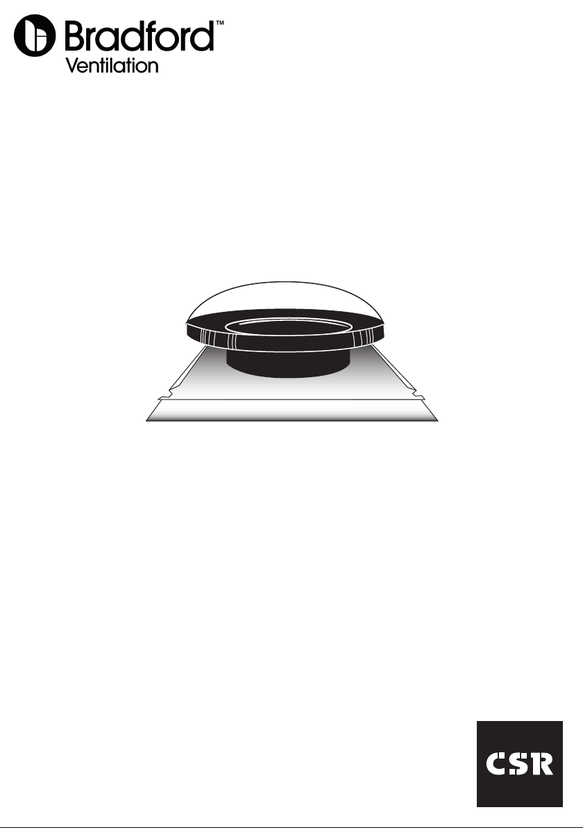
Installation - Tiled Roof
STEP 1
Directly above the
ceiling hole, select a
suitable position for
the SolaBrite on the
roof and it should be
no higher than the third
row of tiles down from
the ridge.
Take care to check
that there are no
obstructions below the
tile such as a rafter.
The removal of a tile higher than the third row down from the ridge
may damage the ridge tile pointing and is NOT recommended.
Recommended SolaBrite Positioning - Minimum third row of tiles from
the ridge cap to a maximum of the fourth row of tiles from the ridge
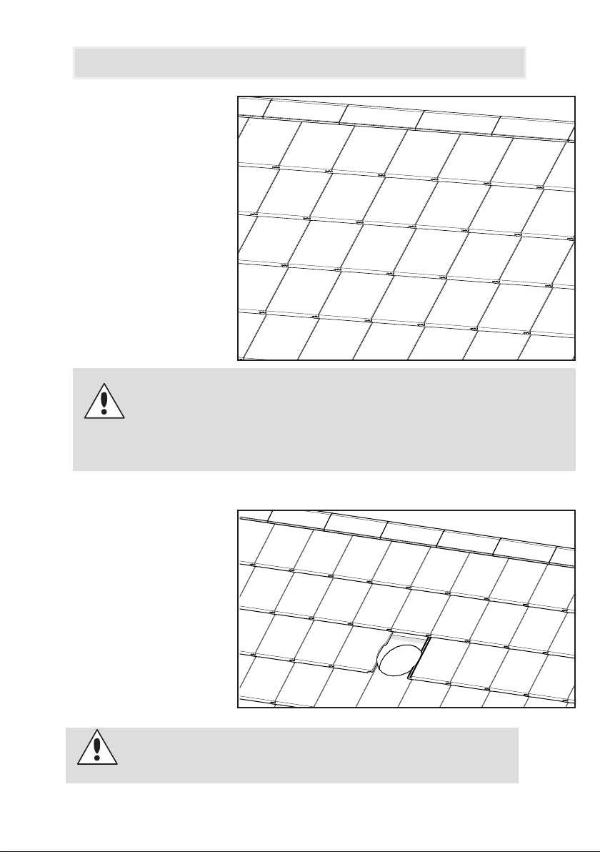
STEP 2
Position the SolaBrite in
the desired location and
mark the tile to be re-
moved and cut using the
ashing hole as template.
Ensure that the product
orientation is correct (refer
to the sticker on ashing).
If a complete tile is removed, then care must be taken to
dress the ashing to ensure a weather tight installation.
7
Installation - Tiled Roof
STEP 3
Fold up the top edge of
the ashing before tuck-
ing it into the tiles.
Fold and form the bot-
tom edge of the ashing
to seal against the tiles
below.
Using a soft hammer,
carefully dress the bottom
edge and the sides of the
ashing into the shape of
the tiles.
STEP 4
Weatherproof the ashing
by applying sealant under-
neath the ashing.
To apply, lift the formed
ashing and run a bead
3-5mm in from the edge
of the ashing edge on
the roof sheeting. Then t
the ashing.
8
Installation - Tiled Roof
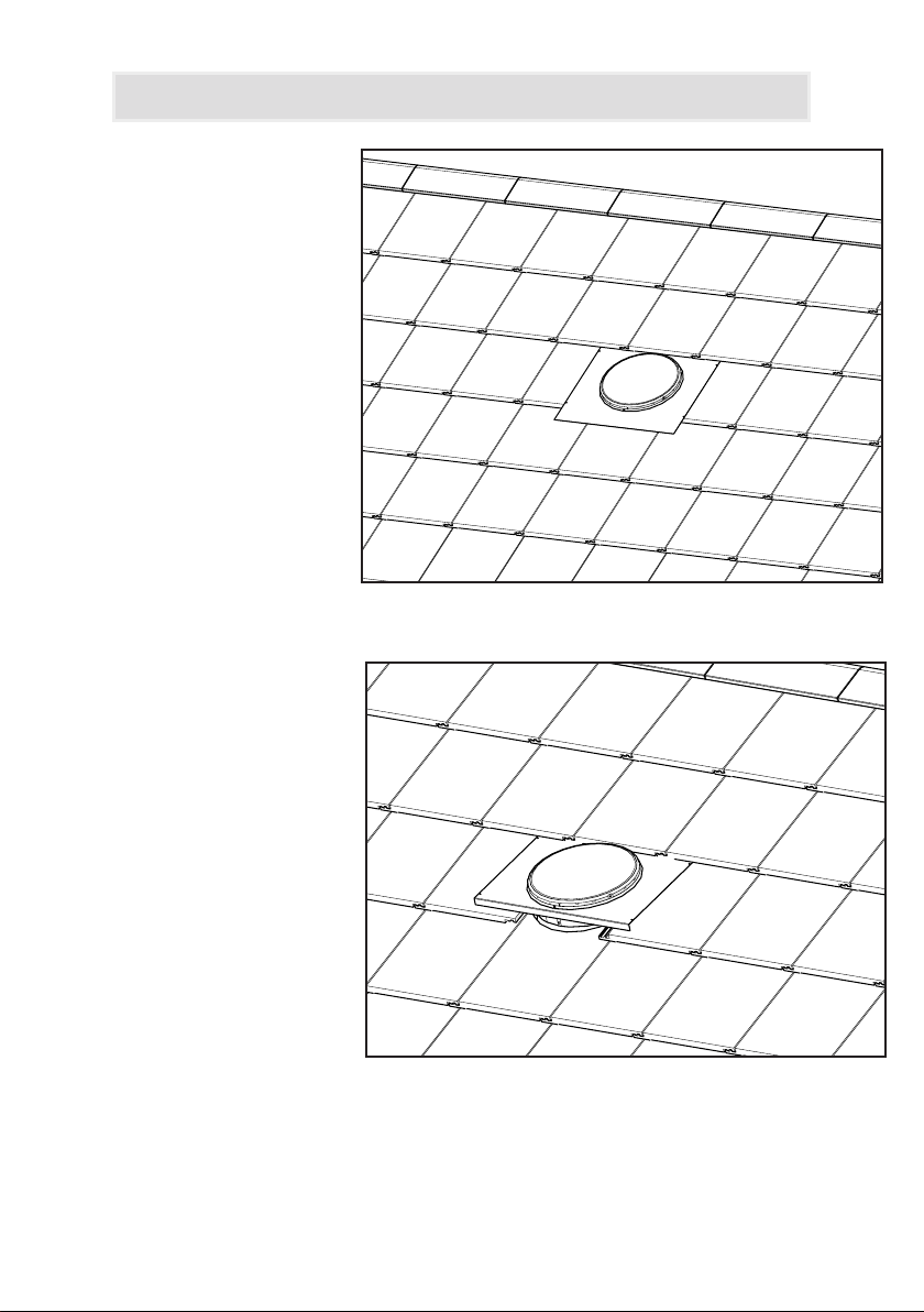
STEP 5
Remove the clear protective
lm from inside of the ue.
Drop the exitube through
the hole in roof and slide
base ashing into position.
Fix the exitube to the ue
underneath the ashing us-
ing the stainless steel tabs
bent outwards. Seal with the
duct tape provided.
Fit the SolaBrite into place
and ensure surrounding tiles
are tted securely.
STEP 6
From inside the ceiling pull the exible tube tightly and cut off excess length.
Secure the tube to the reector ring on the diffuser by bending the push out tabs
and sealing with the duct tape provided.
9
Installation - Metal Roof
STEP 2
Cut the metal roof slightly larger than exitube. Turn up the corrugations or pans on
both the low and high sides. This will help to prevent water ingress.
Ensure that the ashing covers the roof corrugations or ribs equally
and that it is located between roof rafters.
Recommended Vent Positioning - Ideally at the ridge cap but no lower
than 1.2m from the ridge cap.
Backashing required if product assembled away from the ridge cap
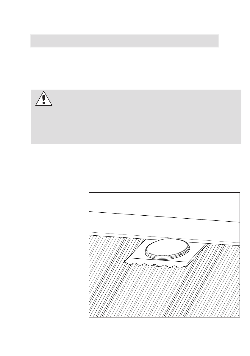
STEP 3
Return the SolaBrite
to the roof, positioning
it over the cutout.
Ensure that the top of
the ashing is slipped
under the ridge capping.
Turn up the top edge
of the ashing before
slipping under ridge
capping. This will help
prevent water ingress.
Ensure that the product
orientation is correct.
(refer to the sticker on
ashing).
STEP 1
From the underside of the metal roof decide approximately where you would
like your solabrite. Punch a hole through the center of the desired position.
10
Installation - Metal Roof
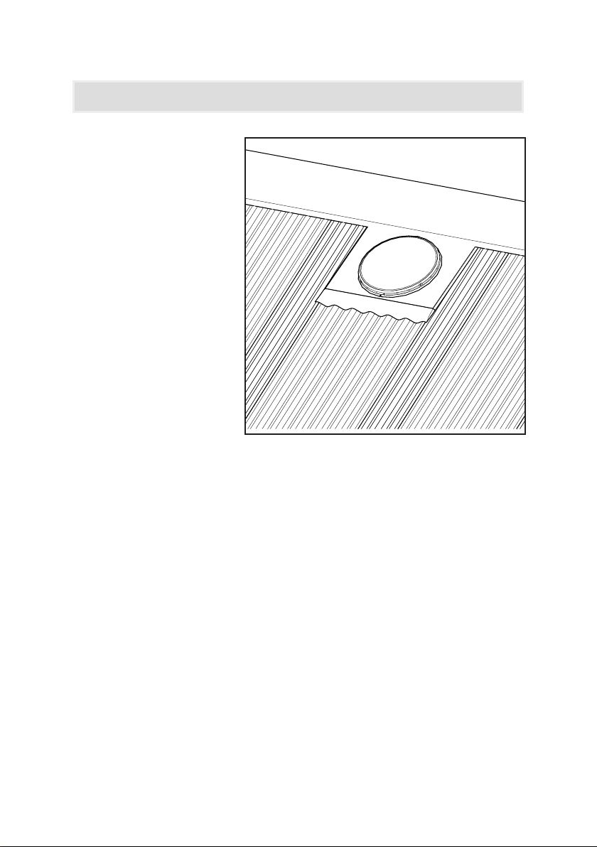
STEP 4
Using a soft rubber
hammer, carefully
work around the sides
and lower edge of the
ashing to form it into the
corrugations of the metal
sheeting prole.
STEP 5
To assist with weatherproong a bead of silicone sealant can be applied be-
tween the sheeting and the side and bottom edge of the ashing.
To apply, lift the formed ashing and run a bead 3-5mm in from the edge of
the ashing edge on the roof sheeting. Then t the ashing.
STEP 6
From inside the ceiling drop the diffuser into place and press to engage in
diffuser rest if used [see step 4 in Ceiling Frame Installation section]. Pull
exitube and cut length before securing it to the reector ring with duct tape.

11
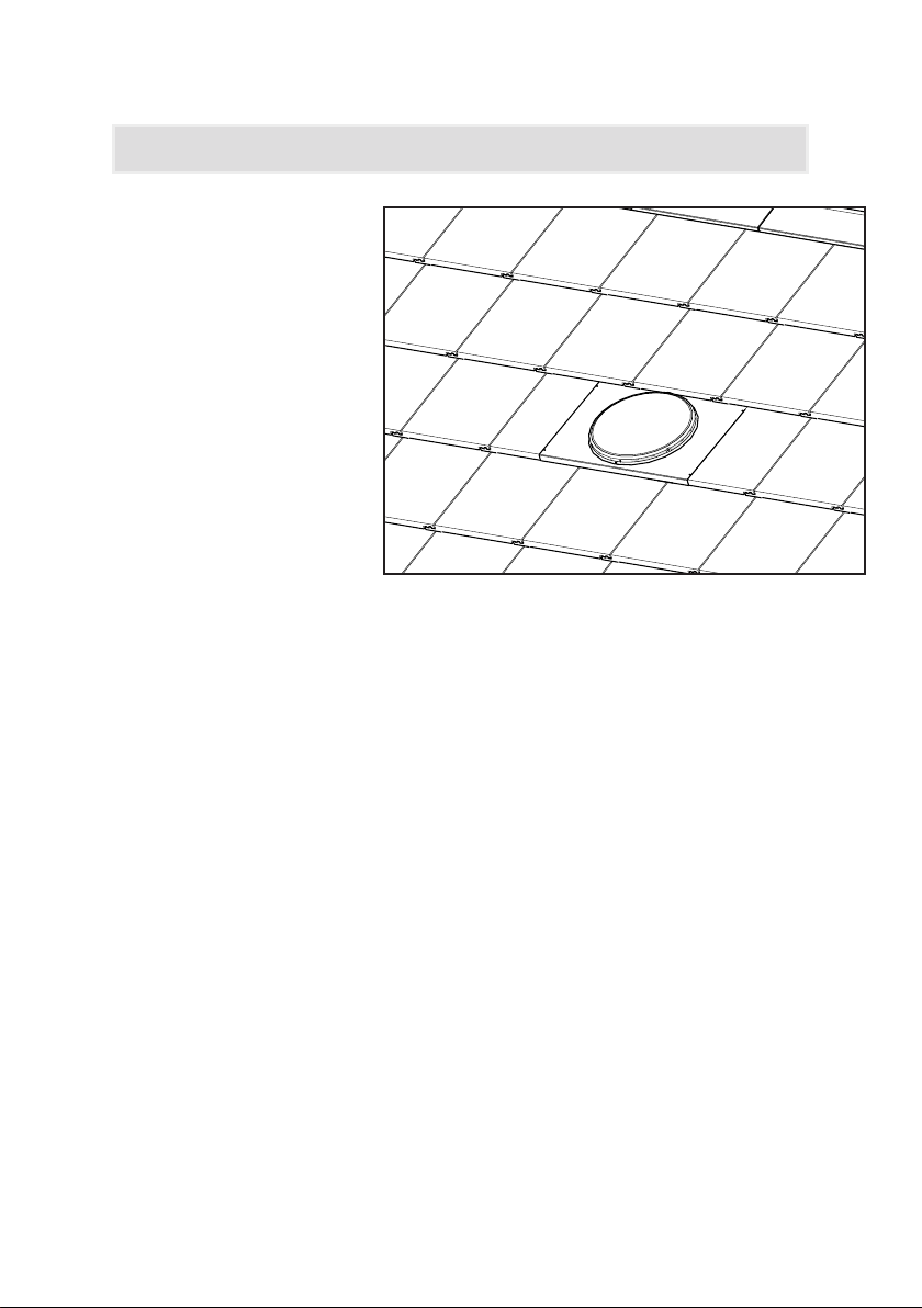
Installation - Metal Roof
Additional Illustration

12
Bradford Ventilation SolaBrite Installation Manual 03/2021
This manual suits for next models
1
Popular Lighting Equipment manuals by other brands

Signtex
Signtex MoonLite LED MAE-AC Series Installation instructions and owner's manual

LIGHTSIDE
LIGHTSIDE LED BALL user manual

Loevschall
Loevschall F15-350E instruction manual

Conrad
Conrad 86 07 48 operating instructions

Ikan
Ikan Lightstar LS-2500E quick start guide

Fiilex
Fiilex Matrix II RGBW quick start guide

Commercial Electric
Commercial Electric 54655241 Use and care guide

hudson valley
hudson valley L1054 installation instructions

RSA Lighting
RSA Lighting C-700 Specification sheet

Light O Rama
Light O Rama SASQUATCH MEGATREE Assembly instructions

Aputure
Aputure light Dome150 product manual

WDM
WDM WEIHRAUCH Masterpiece No.01 quick start guide


