manuals.online logo
Brands
  1. Home
  2. •
  3. Brands
  4. •
  5. Landscape Forms
  6. •
  7. Lighting Equipment
  8. •
  9. Landscape Forms FGP User manual

Landscape Forms FGP User manual

INSTALLATION PROCEDURE FOR LIGHT POLE:
1. Lift the light pole into position over the installed anchors (refer to FGP area light
anchor kit installation guide) as shown in Fig. 1. Ensure that the base plate is resting
on all four washers.
2. Install washers and hexs nut as shown in Fig. 2.
3. Plumb and level the pole and tighten all anchors.
4. Connect line-in wires to driver plate assembly. Pass wires through strain relief. See
Fig. 3. Refer to wiring diagrams on page 3.
5. Ensure that the wire harness connectors are pulled through the top of the driver
plate assembly through the front cavity. This is to connect the luminaire wiring.
6. Gently insert the driver plate assembly into the top of the pole. Ensure the front of
driver plate assembly is in the correct orientation. See Fig. 3 and 4.
7. Apply downward pressure to compress the gasket. Tighten the six hex bolts equally
using a 13mm wrench until snug. Ensure that once tightened, the driver plate
assembly rests in the center of the pole.
8. Connect luminaire wiring to driver plate assembly, see Fig. 5.
9. Gently push wires down inside of driver plate assembly. Set Luminaire on top of
driver plate assembly, ensuring that the luminaire mount plate is seated properly on
the top of the driver plate assembly. Use an 8mm hex key to install M10 x 55m socket
head cap screw and sealing washer to secure luminaire to top of pole.
10. If twist lock receptacle is specified, remove shorting cap and install photo-eye control
(not included), see Fig.6.
11. Install the cover plate as shown in Fig. 7 and 8. Use a 5mm hex key to tighten internal
socket head cap screws to secure the two halves together.
Tools Required
•Safety glasses
•Wrenches, 1-1/4” , 13mm
•Screwdrivers, Phillips and straight blade
•Wiring tools and connectors
•Proper personnel, crane or lift for hoisting unit onto anchors
•Level
•Dimming control, if required
•Hex keys, 8mm with 10-12” extension, 5mm
•Twist lock photo eye control, if required
Landscape Forms is not responsible for site preparation and footings. Refer to the
installation guide for the FGP light anchor kit for installing the anchor bolts.
CAUTION! This unit is heavy. To avoid injury or damage to the finish, we recommend
using a crane or lift for hoisting the unit onto the anchors.
WARNING! Pole mounted luminaires must be attached either before or immediately
after pole installation. Failure to do so may cause vibration damage to the pole and will
void the pole warranty.
ASSEMBLE WITH CARE! Pangard IIPolyester Powdercoat is a strong, long-lasting finish. To
protect this finish during assembly, place unwrapped powdercoated parts on packaging foam or
other non-marring surface. Do not place or slide powdercoated parts on concrete or other hard
or textured surface –this will damage the finish causing rust to occur. Use touch-up paint on any
gouges in the finish caused by assembly tools.
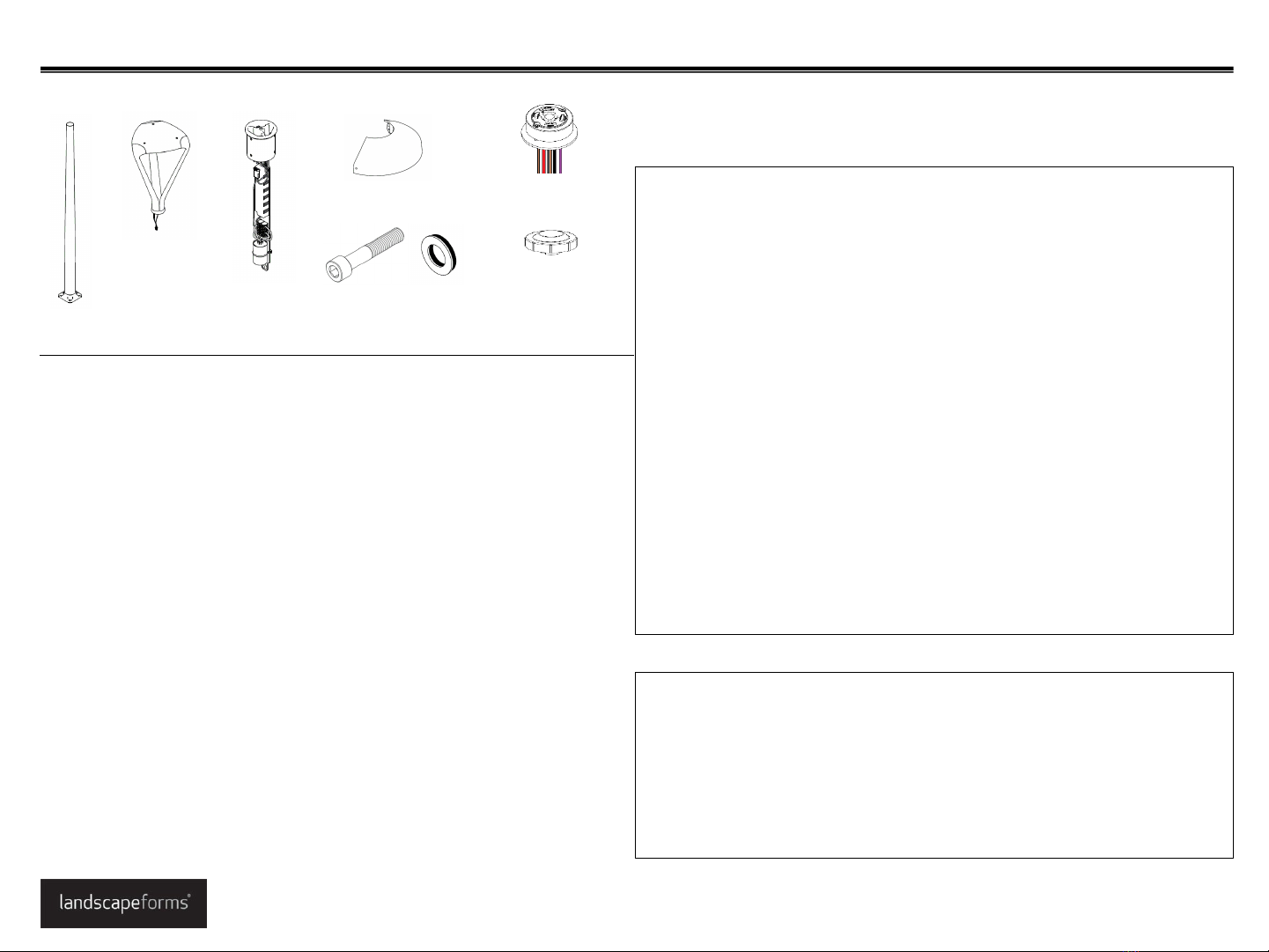
Luminaire
2x -Cover plate half Twist lock receptacle,
optional
Installation Guide
FGP Area Light
www.landscapeforms.com Ph: 800.521.2546
Date: March 19, 2021
Page 1 of 3
Included components
Shorting cap for
Twist lock, optional
Pole
Driver plate
assembly 1x -M10 x 1.5 x 55mm
socket head cap screw
with sealing washer
INSTALLATION PROCEDURE FOR OPTIONAL PHOTO EYE:
Refer to wiring diagram for wiring details.
1. Remove the twist lock cap from the top of the light.
2. Loosen the two phillips head screws two turns.
IMPORTANT! Do not remove the screws. Loosen just enough to rotate the receptacle.
3. Rotate the receptacle until the arrow points north. Tighten the screws.
4. Install the photo eye (not supplied with unit) rated for proper line voltage (277v,
1.5A).
WARNING!: LED cartridge and driver are not rated for connection or disconnection while
energized. Doing so may damage LEDs and will void the warranty. Disconnect incoming
power before making or breaking any electrical connections.
Installation Guide www.landscapeforms.com Ph: 800.521.2546
Page 2 of 3
FGP Area Light
Fig. 1 –Pole orientation
Fig. 8 –Install cover plates
ACCESS HOLE FOR
SECURING COVER
PLATES TOGETHER
INSTALLED SCREWS
FOR RETAINING
BASE PLATE
5MM HEX KEY
Fig. 5 -Install luminaire
LUMINAIRE
M10x1.5mm x
55mm SHCS
SEALING
WASHER
WIRING
HARNESS
Fig 7. –cover plate section
POLE BASE PLATE
RETAINING SCREWS
COVER
PLATE
Fig. 2 –Install pole
HEX NUT
FLAT
WASHER
Fig.6 –Optional twist lock receptacle
SHORTING CAP
#6-32 PHILLIPS
FLAT HEAD
MACHINE SCREWS TWIST-LOCK
RECEPTACLE
Fig. 4 –Secure driver plate
13mm
WRENCH TO
TIGHTEN
FRONT
Fig. 3 –Install driver plate
DRIVER PLATE
TERMINAL
BLOCK
SURGE
PROTECTOR
POLE
STRAIN RELIEF
Date: March 19, 2021
PROCEDURE FOR WIRING FGP:
The FGP luminaire is assembled at the factory. The light cartridge is mounted into the head of the luminaire and will not need to be removed during installation. The LED cartridge
needs to be connected to the driver plate assembly on site. Use of LED drivers other than the supplied unit is not recommended and will void the warranty.
The wiring schematics are to be used to connect the unit to line voltage. It is the responsibility of the installer to make sure that all connections are made in accordance with the NEC
and local building codes. Connection hardware not included.
Line-in wires should be connected to the terminal block as shown. Optional dimming control is not included.
WARNING!: LED cartridge and driver are not rated for connection or disconnection while energized. Doing so may damage LEDs and will void the warranty. Disconnect incoming
power before making or breaking any electrical connections.
Note: Type 3 drivers do not include a ground wire.
Installation Guide www.landscapeforms.com Ph: 800.521.2546
Page 3 of 3
FGP Area Light
WIRING DIAGRAM: No twist lock, With ground WIRING DIAGRAM: With twist lock, with ground
Date: March 19, 2021

Other Landscape Forms Lighting Equipment manuals

Landscape Forms Torres User manual

Landscape Forms

Landscape Forms Torres User manual

Landscape Forms Torres User manual

Landscape Forms

Landscape Forms Torres User manual

Popular Lighting Equipment manuals by other brands

Life 39.9F70020C quick start guide

Life

Life 39.9F70020C quick start guide

EuroLite LED ML-20 user manual

EuroLite

EuroLite LED ML-20 user manual

LIGMAN OD-50141 installation manual

LIGMAN

LIGMAN OD-50141 installation manual

Home Accents Holiday 1002461144 instructions

Home Accents Holiday

Home Accents Holiday 1002461144 instructions

Experia IRiS Ripple Light instruction manual

Experia

Experia IRiS Ripple Light instruction manual

Erco Gecko Mounting instructions

Erco

Erco Gecko Mounting instructions

Inter-lux ZTA.100.Surface Installation and maintenance instructions

Inter-lux

Inter-lux ZTA.100.Surface Installation and maintenance instructions

Whelen Engineering Company TN Series installation guide

Whelen Engineering Company

Whelen Engineering Company TN Series installation guide

IKEA BJÖRKSPIREA manual

IKEA

IKEA BJÖRKSPIREA manual

Toolland PM 6640 instruction manual

Toolland

Toolland PM 6640 instruction manual

GTD GTD-LP200 user manual

GTD

GTD GTD-LP200 user manual

LIVARNO home 1105-W-UK manual

LIVARNO home

LIVARNO home 1105-W-UK manual

ProLights EclPar IPMFC user manual

ProLights

ProLights EclPar IPMFC user manual

Velvet EVO Series user manual

Velvet

Velvet EVO Series user manual

IDTOLIGHT GENT installation instructions

IDTOLIGHT

IDTOLIGHT GENT installation instructions

MAYTONI S35 installation manual

MAYTONI

MAYTONI S35 installation manual

MaxLite MLFP14DP4535 user manual

MaxLite

MaxLite MLFP14DP4535 user manual

SLV Elektronik 550621 instruction manual

SLV Elektronik

SLV Elektronik 550621 instruction manual

manuals.online logo
manuals.online logoBrands
  • About & Mission
  • Contact us
  • Privacy Policy
  • Terms and Conditions

Copyright 2025 Manuals.Online. All Rights Reserved.