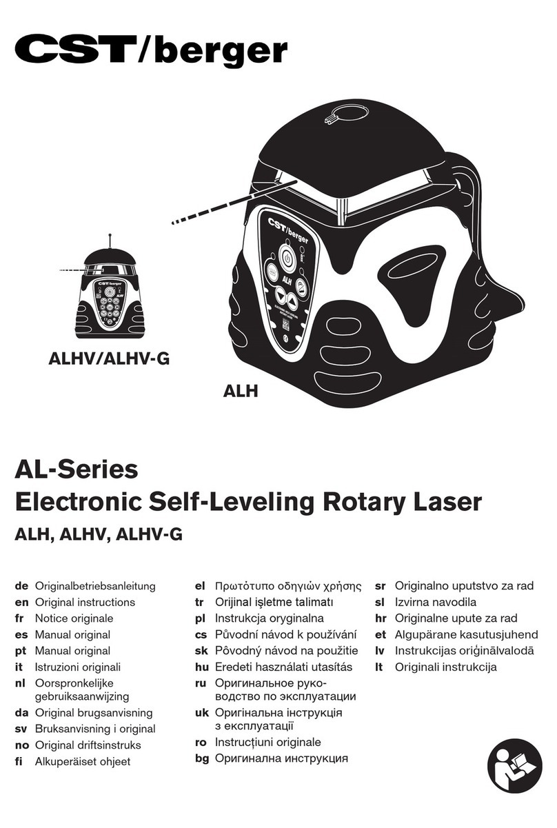
CST/BERGER ALH User manual

Electronic Self-Leveling
Electronic Self-Leveling
Rotary Laser
Rotary Laser
Instruction Manual
Manual de Instrucciones
Manuel d’Instructions
Manuale di Istruzioni
Bedienungsanleitung
Instruções de Utilização
Electronic Self-Leveling
Rotary Laser
models:
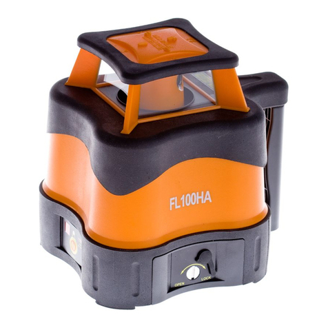
ALH, ALHV, ALHV-G, ALGR
ALH
ALHV(-G)
ALGR
3
Electronic Self-Leveling
Rotary Laser
www.cstberger.com
3

2• AL-SERIES
LD440
Electronic Self-Leveling
Rotary Laser
3
3

Fig. 4
ALHV
Fig. 5
ALHV
Fig. 6
ALGR
MODE
SELECTSELECT
VERTICALLINE
PLUMB BEAM
Fig. 7
Y-Axis
Y
“MORE”
X
“MORE”
“LESS” “LESS”
ALGR
MODE
SELECT SELECT
X—AXIS ERROR
Y—AXIS ERROR
SPINDLE ERROR
AL-Series Errors
Fig. 8 Fig. 9
Fig. 10
AL-SERIES • 3

4• AL-SERIES
Thank you for purchasing- the CST/berger AL-Series Automatic Electronic Self-Leveling
Rotary Laser Level. Please read this manual thoroughly before operation
MODELS
ALH ALH Visible Horizontal Beam Electronic
Self-Leveling Single Slope Rotary Laser.
ALHV ALHV Horizontal/Vertical Visible Dual-Beam Electronic
Self-Leveling Dual-Slope Rotary Laser.
ALHV-G ALHV Horizontal/Vertical Visible Dual-Green Beam Electronic
Self-Leveling Rotary Laser.
ALGR ALHVGR Horizontal/Vertical Visible Dual-Beam Electronic
Self-Leveling Rotary Laser with Dual Dial-in Grade.
Copyright© 2010 Robert Bosch Tool Corporation.
The information contained herein is proprietary information of CST/berger, and is subject to change
without notice. This document shall not be copied or otherwise reproduced without CST/berger's
written consent.
SAFETY AND CERTIFICATIONS
Working safely with this instrument is possible only when the operating and safety information are
read completely and the instructions contained therein are strictly followed.
The use of controls, adjustments, or the performance of procedures other than those specified
herein may result in hazardous radiation exposure.
Do not stare into the laser beams. Do not direct the laser beam at other persons. Do not
disassemble the instrument or attempt to perform any internal servicing. Laser class is indicated
on the instrument.
Repair and servicing of this laser are to be performed only by CST/berger or authorized
service centers.
This laser complies with all applicable portions of title 21 of the Code of Federal Regulations set by:
the Dept. Of Health, Education, and Welfare; the Food and Drug Administration; the Center for
Devices; and the Bureau of Radiological Health.
The laser has also been tested and complies with the CE certification requirements set forth in the
EC regulations 89/336/EEC and EN 61000-6-1 (EN50082-1), EN 61000-6-3 (EN50081-1) and IEC 60-825-1.
ACCORDING TO IEC/EN 60825-1: 2007
EN
ACCORDING TO IEC/EN 60825-1: 2007

LASER SAFETY
WARNING: Be sure to read and understand all instructions in this manual before using this
product. Failure to follow all instructions may result in hazardous radiation exposure,
electric shock, fire, and/or bodily injury.
CAUTION: Use of controls or adjustments or performance of procedures other than those
specified in this manual, may result in hazardous radiation exposure.
CAUTION: The use of optical instruments with this product will increase eye hazard.
IMPORTANT: The following labels are on your laser for your convenience and safety. They indicate
where the laser light is emitted by the level.
ALWAYS BE AWARE of their location when using the level.
ALWAYS make sure that any bystanders in the vicinity of use are made aware of the dangers of
looking directly into the laser.
DO NOT remove or deface any warning or caution labels. Removing labels increases the risk of
exposure to laser radiation.
DO NOT stare directly at the laser beam or project the laser beam directly into the eyes of others.
Serious eye injury could result.
DO NOT place the laser in a position that may cause anyone to stare into the laser beam
intentionally or unintentionally. Serious eye injury could result.
DO NOT use any optical instruments such as, but not limited to, telescopes or transits to view the
laser beam. Serious eye injury could result.
ALWAYS remove the batteries when cleaning the laser light aperture or laser lens.
DO NOT operate the laser around children or allow children to operate the laser. Serious eye injury
could result.
ALWAYS turn the laser "OFF" when not in use. Leaving the laser "ON" increases the risk of someone
inadvertently staring into the laser beam.
DO NOT operate the laser in combustible areas such as in the presence of flammable liquids,
gases or dust.
ALWAYS position the laser securely. Damage to the laser and/or serious injury to the user could
result if the laser falls.
ALWAYS use only the accessories that are recommended by the manufacturer of your laser. Use of
accessories that have been designed for use with other rotary lasers could result in
serious injury.
DO NOT use this laser for any purpose other than those outlined in this manual. This could result in
serious injury.
DO NOT leave laser "ON" unattended in any operating mode.
ALWAYS repair and servicing must be performed by a qualified repair facility. Repairs performed
by unqualified personnel could result in serious injury.
DO NOT disassemble the laser. There are no user serviceable parts inside. Disassembling the
instrument will void all warranties on the product.
DO NOT modify the product in any way.
AL-SERIES • 5

6• AL-SERIES
ALH ALGRALHV ALHV-G
Interior / Interior / Interior
Exterior / Exterior / Exterior
±10%
±10%
3
Electronic Self-Leveling
Rotary Laser
FEATURES
Low Battery Indicator
Anti-Drift System
Single Slope/Grade
Dual Slope/Grade
Cross-Axis Leveling
Dual-Beam
Scanning Angle
Feature
Directional Head
Positioning
Variable Speed
Rotation
LayDown Auto-beam
Positioning
LCD- On Board
Digital Display

AL-SERIES • 7
3
Electronic Self-Leveling
Rotary Laser
A
B
C
D
E
G
F
H
I
J
K
FEATURES - Fig. 1 , 2 & 3 ICONS
1. Self-Leveling (+/-5º) Rotating
Laser Head. (With vertical visible dual-beam
ALHV, ALHV-G, ALGR only)
2. Battery Low LED Indicator Light
When indicator lights reach Yellow it is time to
change/recharge batteries.
(ALH, ALHV, and ALHV-G only)
3. Anti-Drift System LED Indicator
(ALH, ALHV, ALHV-G only)
4. Power ON/OFF LED Indicator
5. Manual Mode LED Indicator
(ALH, ALHV, ALHV-G only)
6. Manual Grade Adjustment Buttons (ALH,
ALHV, ALHV-G)
7. 5/8 - 11 Tripod Mounting Threads (for level work)/
Battery pack.
8. Gun Sight with “X” and “Y” Identifiers
9. Heavy-Duty Handle-(Built in Trivet for Laydown
and Vertical Applications with 5/8 - 11 Thread
ALHV, ALGR, and ALHV-G only)
10. Select/Adjustment Buttons (ALGR only)
11. LCD Display Panel (ALGR only)
12. Mode Selection Button (ALGR, only)
13 Vertical Beam ( ALHV, ALHV-G, ALGR )

8• AL-SERIES
1
5
4
89 7
3
2
6
ALH Fig. 1

AL-SERIES • 9
ALHV & ALHV-G Fig. 2
8
9
7
ALHV
ALHV
1
3
4
2
13
6

10 • AL-SERIES
ALGR Fig. 3
8
9
7
ALGR
MODE
SELECT SELECT
1
11
10
12
ALGR
MODE
SELECT SELECT
13

AL-SERIES • 11
3
Electronic Self-Leveling
Rotary Laser
NOTE: Setup a Benchmark
During the work day, periodically check your initial
set-up to ensure that the laser reference
has not moved.
Establish, at a suitable distance (furthest possible), a
benchmark (reference) on a stable surface (ie. tree,
building). Periodically during the work day, check the
benchmark to ensure that your setup has not moved.
APPLICATIONS
Benchmark.
Professional-grade Accuracy
and Durabillity for general
construction and site preparation
jobs,
Including,
• Grading and excavation
• Porch and deck construction
• Driveway paving
• Exterior siding
• Marking elevation
• Landscaping
• Pool Installation
• Fencing
• Masonry work
• Concrete forms
• Machine control
• Building room addition
• Remodeling
• Walls and partitions
• Acoustical ceilings
Exterior- ALH, ALH, ALHV-G, ALGR
Interior-ALHV, ALHV-G, ALGR

12 • AL-SERIES
Operating Instructions for General Construction Applications
NOTE: A level plane of laser light is created by the rotating beam of the laser. The laser light can be
used to reference elevations with the use of a laser detector. (Fig. 4)
1. Place the instrument on a flat, level surface such as a tripod. Setup the instrument in an
area where it can not be obstructed and is set at a convenient height.
2: Press the (A) button. Allow the instrument to self-level.
3. Setup a "Benchmark" .
4. ALHV, ALHV-G ALGR Only – Set the Variable Speed Rotation (page 14 ) to the desired
rotation speed of the laser head. Ideal speed for use with laser detector is 600 RPM.
5. Take elevation readings using the plane of laser light as a reference.Follow the Detector
Operation Procedures in this manual.
Ceiling Grid Applications
1. Attach the laser to the optional wall-mount bracket. Be sure the control buttons are facing
outward. Tightening the locking screw will secure the instrument to the bracket.
2. After installing the first piece of ceiling trim, attach the wall-mount to it. Be sure the
wall-mount is secure to the trim.
3. Press the (A) button. Allow the instrument to self-level.
4. Adjust the distance of the instrument from the grid, typically 1.5-inch (38mm) below the grid.
Loosen the adjustment screw and slide the instrument up/down on the wall mount. When
the desired height has been reached, tighten the adjustment screw to secure the instrument.
5. Setup a "Benchmark" (page 11).
6. Install the ceiling grid. Attach the magnetic laser target to the ceiling trim being installed.
Adjust the height of the trim until the laser beam strikes the target.(Fig. 5)
Laydown Applications (ALHV, ALHV-G, ALGR)
1. Place the instrument in the laydown position on a flat, level surface.
2. Press the (A) button. Allow the instrument to self-level.(Fig. 6)
3. Setup a "Benchmark" (page 11).

AL-SERIES • 13
OPERATION
Remove the laser from its carrying case. The instrument is shipped with a battery current
protection insert, which must be removed before operation.
NOTE: All ALH and ALHV(-G) instruments are shipped with ADS on as the default setting. This
setting can be changed by the user (see Anti-Drift System - ADS, page 16).
NOTE: ALGR instruments will default to Grade Mode when the instrument is turned on. The Mode
button is used for both selecting between the X-axis and Y-axis for setting grade and exiting
the Grade Mode (see Grade Mode — Dual or Single Axis Grade). Press and release the
Mode button to select between the X-axis and Y-axis when setting grade. To exit the Grade
Mode, press and hold the Mode button for 4 to 5 seconds, then release. This will bring up
the Mode Select Menu. The user can now toggle to other menu options. Pressing the Mode
button for 4 to 5 seconds and releasing is only required to exit the Grade Mode.
Leveling
1: The instrument can stand alone on a level, sturdy surface or preferably secured to a 5⁄8-11
surveyor’s tripod.
2: Press the (A) button once, and allow time (up to 60 seconds) for the instrument to self-level.
NOTE: The laser head may begin to rotate before leveling is complete. The self-leveling speed is
approximately 1° per 4 seconds.
3: After self-leveling, the instrument will begin operating in Rotation Mode.
NOTE: The ALHV,ALHV-G will return to last mode of operation (i.e. sweep, spot, or rotation speed);
however, does not retain grade information.
NOTE: After self-leveling, the instrument will begin operating in Rotation Mode for ALH, last selected
mode of operation (i.e. Sweep, Spot, Rotation Mode) for ALHV, ALHV-G, and Grade Mode
for ALGR.
Cross Axis Leveling (Models ALH, ALHV, ALHV-G)
NOTE: ADS must be off to enable cross-axis leveling.
1. Press the Manual mode (C) button once to enable cross-axis leveling. The instrument will level in
the x-axis only. The manual grade can be set in the y-axis only.
2. Press the Manual mode (C) button again to shut off the cross-axis leveling and to place the
instrument into Manual mode.
NOTE: When the ADS is off, the remote Mode button will place the instrument in cross-axis leveling
with the first press and in Manual mode with the second press.
Plumbing / Lay-Down (Models ALHV and ALHV-G)
1. On a flat surface, place the instrument on its back using the built-in trivet (control panel
facing upward). (Fig. 7)
2. Press the (A) button once, and allow time for the instrument to self-level.
NOTE:When the Instrument is placed in the laydown position, the ADS button (B) becomes the
Auto Beam Positioning button.

14 • AL-SERIES
3. Enable the Auto Beam Positioning by turning off ADS if it is on, and by placing the instrument
in SPOT mode. (ADS will not be available in Spot mode once it is turned off).
4. Press the Auto Beam Positioning (B) button; the laser beam will plumb down over point.
(Reference Only).
5: Use the clockwise (F) and counter-clockwise (G) buttons for fine adjustment. Plumbing /
Lay-Down (Models ALHV, ALHV-G and ALGR)
NOTE: For fine adjustment of the vertical laser plane or of the 90° beam, please refer to “Line Position”
Variable Rotation Mode (Models ALHV, ALHV-G and ALGR
The rotation mode will give you the option of increasing or decreasing the speed of the rotating
laser. This feature can be used to create a room-wide, 360° height reference or vertical plumb line
for general alignment, drop ceiling installation, and more.
model ALHV, ALHV-G
Pressing the (E) button, will adjust the speed from
600, 300, 150, and 0 RPM.
model ALGR
Using the SELECT buttons, adjust the rotation speed in increments of 50 RPM; lowest possible
speed is 100 RPM and the highest is 1000 RPM.
Sweep or Scanning Mode (Models ALHV, ALHV-G and ALGR)
Instead of creating a room-wide reference line, the Sweep (Scanning) Mode creates a shorter,
brighter laser “chalk line” that can be used for leveling or plumbing doors, windows, fixtures, and
more. You may also use this feature to keep the instrument from interfering with other lasers and
detectors on site.
model ALHV, and ALHV-G
Pressing the (D) button, will lengthen or shorten the sweep of the laser beam. Preset angles of 10º,
45º, 90º,180º and spot can be set. Position the sweep area by using the (F) or (G) buttons.
model ALGR
Using the MODE button to enter the "POSition"
option, and use the SELECT buttons to position the
sweep clockwise or ccw. Press the MODE button to
return to SWEEP SETUP. Use the right SELECT button
to enter the “LENGTH” option and use the
corresponding SELECT buttons to lengthen or
shorten the sweep of the laser beam to the
appropriate length for your application. The sweep
can be as long as 359° or as short as 3°. The last sweep setup entered remains in memory and will
be recalled.
FAST SLOW
ROTATE 600
SELECT
ROTATION
SELECT
SWEEP SETUP
POS LENGTH
SWEEP SETUP
CCW CW
SWEEP POS
LONG SHORT
SWEEP LENGTH

AL-SERIES • 15
Point-to-Point Mode (Model ALGR)
Similar to the Sweep Setup mode, the Point-To-Point Mode allows
you to create a laser “chalk line”, sweeping between any two
positions you specify.
Use the left SELECT button to enter the “PTP: SET PT A” option,
and use the SELECT buttons to rotate the position of the start point
clockwise or counterclockwise. Press the MODE button to enter
the “PTP: SET PT B” option, and use the SELECT buttons to rotate
the position of the end point clockwise or counterclockwise. Press
the MODE button to begin the sweeping action between the two
points. You may use the SELECT buttons to readjust the position of
each point if needed.
NOTE: In Sweep or Point-to-Point Mode, the selected sweep area will not be exact. The laser will
vary slightly from the selected points.
Spot Mode (Models ALHV, ALHV-G, ALGR)
Spot Mode creates a motionless laser dot for reference, allowing the instrument to be used as a
straight-line laser.
model ALHV,ALHV-G
Press the (E) button until the instrument is in Spot Mode. Press the (F) or (G) to rotate the laser
head clockwise or counter-clockwise. Pressing and holding the (G) or (F) button moves the rotating
beam more quickly.
model ALGR
Use the SELECT buttons to rotate the position of the dot
clockwise or counterclockwise.
Re-Leveling (Models ALH, ALHV,)
If the instrument is bumped or moved, the instrument will automatically attempt to re-level itself.
On a job site, it may be necessary to prevent re-leveling in order to prevent inaccurate
measurements by the operator. The Anti-Drift System (ADS) is used for this purpose (see Anti-Drift
System - ADS). The instrument can also be placed in Manual Mode to allow the instrument to
continue operating when out of level.
Axis Drive Error (Models ALH, ALHV,)
If the instrument is set up or tipped beyond its self-leveling range of ±5°, the laser head will initially
attempt to level; however, when the self-leveling limit is reached, an error will indicate an axis
error (Fig. 8).
Turn the instrument OFF, move the instrument to a more level position, then turn the instrument
on again.
SELECT
PT TO PT
CCW CW
PTP: SET PT A
CCW CW
PTP: SET PT B
PT A PT B
PTP: SWEEPING
SELECT
SPOT
CCW CW
SPOT

16 • AL-SERIES
Model ALGR
The display shows “X TOO STEEP or Y TOO STEEP” Turn the instrument OFF, move the instrument
to a more level position, then turn the instrument on again.
If the instrument continues to produce errors, contact CST/berger-Customer Service.
Spindle Motor Error
Models ALH, ALHV, ALHV-G
If the laser spindle motor fails to rotate or rotates outside of the set speed, an error indicator will
indicate a spindle motor error (Fig. 8). If this occurs, see “Troubleshooting”.
Model ALGR
The display shows “Spindle Motor Error”.
If the instrument continues to produce errors, contact CST/berger-Customer Service.
Auto Level Mode (Model ALGR)
The Auto Level Mode allows you to control how the instrument reacts when moved out of level.
Model ALGR
Auto Level Mode can be ON, OFF, or ADS. If Auto Level Mode is
set to ON, the instrument will
re-level if the instrument is moved out of level.
If Auto Level Mode is set to OFF, the instrument will NOT re-level
if the instrument is moved out of level, and will continue to
operate; use this option when using an adapter or mount that
allows you to tilt the instrument to create a diagonal laser line.
Use the left SELECT button to turn the Auto Level option ON or
OFF. You may also put the level into ADS Mode ( see Anti-Drift
System- ADS).
Anti-Drift System – ADS ( All Models )
The Anti-Drift System, when ON, will signal to the operator that the instrument has been moved out
of level.The laser head will stop rotating, and the beam and ADS LED will blink in the models ALH,
ALHV; in the model ALGR the display will show “CONT UNIT UNLEVEL”.
Models ALHV, ALHV-G, and ALH
The default setting for ADS is user selectable. The default setting may be set to ADS ON or ADS
OFF. When the instrument is OFF, press and hold the (B) button, and then press the (A) button. Once
the instrument is on, turn the instrument off for 15 sec and then back on. If ADS was ON (OFF), it
will now be OFF (ON).
SELECT
AUTOLEVEL
ON
AUTOLEVEL
OFF
AUTOLEVEL
ADS
AUTOLEVEL

AL-SERIES • 17
To activate ADS, turn off the Manual Mode (if it is ON), by pressing (C) and then press the ADS (B)
button. If after 1 minute, the instrument is disturbed and the ADS light is flashing it is necessary to
check any bench marks that have been made and ensure the proper "HI" (Height of Instrument).
After the flashing ADS has been reset, by pressing the button one time, you will have an additional
minute to set and check your measurements.
To turn ADS off press the (B) button once. This will put the instrument into
normal Auto Self-Leveling mode.
Model ALGR
This function is prompted through the Auto Level Mode; it clearly
signals the user when the instrument is moved out of level. Turn ADS
on by selecting it in Auto Level Mode and using the MODE button to
return to your desired mode. If ADS is turned on, when the instrument
is moved out of level, the laser head will stop rotating and the beam will blink. The operator must
use the right SELECT button to select the “CONTinue” option.
The default setting for ADS is user selectable. When the instrument is OFF, press and hold the right
SELECT button and then press the ON/OFF (A) button. Once the instrument is on, turn the
instrument off for 15 sec and then back on. This will toggle the default setting for Auto Level Mode
between ADS and on.
Manual Grade Mode – Single Axis Grade (Model ALH & ALHV (-G))
The single grade function is ideal for general site grading, checking excavations, landscaping and
drainage, and more. (Fig. 9)
The selected grade can be as much as a positive or negative 10%, and set in reference to the Y
axis of the instrument, noted by the embossed printing on the case.
Model ALH
Manual grade mode can be activated by placing the automatic leveling sensor in the OFF position.
NOTE: The ADS must be deactivated to use the Manual Select button.
Pressing the (C) button will deactivate the level sensor. Using the (H) ("MORE") and (I) ("LESS")
arrow buttons, adjust to your desired grade. Rotating head tilts on the Y axis.
NOTE: If the instrument is bumped or moved while in Manual Grade mode, the instrument will not
re-level itself.
The instrument will react to “MORE” and “LESS” input. Allow the instrument ample time to react to
the input provided, between grade setups or changes. (Fig. 10)
CONT
UNIT UNLEVEL

18 • AL-SERIES
Manual Grade Mode-Dual Axis Grade (Models ALHV, ALHV-G)
Manual mode disengages the leveling feature, allowing the instrument to be placed in any position
to grade.
To activate the Manual Mode, Turn off the ADS (if it is on) and then press the (C) button twice to
enter Manual Grade Mode. (Note: If the button is pressed only once it will enter Cross Axis
Leveling Mode (page13)) (Note: The instrument should be level and rotating before entering manual
mode to eliminate the possibility of error.) Once the button has been pressed the Manual Mode
Indicator Light will blink. Press the (C) button again to return to normal operation.
NOTE: When returning to normal operation the instrument must be within its leveling range. Re-set
the instrument to a level position before pressing the (C) button to the off position.
NOTE: (Model ALHV, ALHV-G) Once the instrument is in manual mode, the remote can be used to
set a slope in the Y-axis by pressing the UP(H) or DOWN (I)button, or X-axis by pressing the remote
LEFT or RIGHT Arrow Button.
Grade Mode – Dual or Single Axis Grade (Model ALGR)
The dual grade function allows more specialized site preparations such as road grading, airport
jobs (grading & paving), irrigation, trenching, landfills, slopes and embankments, and pipe laying. (Fig.11)
The Dual Grade Mode screen is the default screen when the instrument
is turned on. Use the MODE button to choose either the X axis or Y axis.
An > on the display will indicate the selected axis. Press the left SELECT
button to increase slope, press the right SELECT button to decrease
slope. Ideally for single axis grade, use the Y axis in order to use the top mounted sight to orient
the instrument to your target, as well as locate the high and low positions within the arc. While
grade on both axes is set to zero, the instrument will continue to self-level. Percentage of grade
can be selected at any time while in this mode. However, the instrument will not go to the desired
grade until the instrument has leveled.
Allow the instrument ample time to react to the input provided. Refer to examples in (Fig. 12) to
predict your results.
To exit Grade Mode, press and hold the MODE button for 4 to 5 seconds. When the button is
released, the MODE select menu is available. (it is not necessary to press and hold the MODE
button to exit any other mode).
NOTE: The total percent grade possible is from a perfectly level base position. If the instrument is
mounted on a tripod head which is not perfectly level, then the grade percentage range
capability would be reduced by the slope of the base, as this affects the tilt range of the
laser head. For maximum grade range, ensure a level tripod head using a spirit level before
mounting your instrument.
FOR ALL GRADE LASERS: For greater accuracy in grade applications, precisely level the laser
level before entering into GRADE MODE.
FOR ALGR: If the instrument can’t achieve desired grade it will give an error
message “GRADE TOO STEEP”
+ >X 0.00% –
>Y 0.00% –

AL-SERIES • 19
Anti-Drift in Grade Mode (Models ALGR)
The Auto Level Mode can be set to ADS while instrument is in
Grade Mode. ADS will protect against accidental bumps or
settling of the instrument that could cause errors. If the
instrument has been setup to default to Auto Level ADS at startup,
the Grade Mode ADS is already on. If the instrument has not been
set up to default to Auto Level ADS at startup, enter the Auto
Level Mode and selecting ADS. Return to Grade Mode after
selecting ADS. ADS will only be active as long as one axis is set
to zero percent grade (Single Axis Grade). ADS will not be active
while in Dual Axis Grade. ADS is automatically disabled for 30
seconds whenever a new set point is entered for the grade axis.
In Grade Mode, when the instrument is moved out of grade level,
the laser head will stop rotation and the beam will blink to indicate
to the operator that the HI of the instrument may have changed.
To continue, the operator must acknowledge by pressing the right SELECT
button to select the “CONTinue” option.
NOTE: If movement occurs in only the grade axis, ADS may not indicate movement since the
movement is being detected by the non-grade (level) axis. However, in a real world
application, both the grade and level axis will likely move.
Line Position Mode (Model ALHV, ALHV-G and ALGR)
In this mode, the instrument allows you to fine-tune the location of your vertical (plumb) laser line.
For example, if you’ve established a plumb line and find that the line is slightly off to the left or right
of your target, use Line Position to jog the line into place without moving the entire instrument
(useful for floor and wall tile installation, walls or partitions, etc.). The laser will now remain aligned
to your target even if you enter other modes (Rotation, Spot, Point-to-Point)
model ALHV, ALHV-G
Line Position mode is available when the instrument is placed in the plumbing position (control
panel facing upward). While the instrument is in the plumbing position, it can be used in Rotation,
Sweep or Spot mode. To enter the Line Position mode and position the laser reference point the
instrument must be rotating. Use the (F) or (G) buttons to position the laser reference point while
the instrument is rotating ( Fig. 13). If the instrument is in Spot or Sweeping mode the (F) and (G)
buttons are used to move the spot or sweep clockwise and counterclockwise, as they do when
the laser is in the upright position.
NOTE: The LEFT and RIGHT buttons of the RC700 Remote can be used to position the reference line
regardless of the instrument being in Rotation, Spot, or Sweep Mode.
If in manual mode , the LEFT and RIGHT buttons will position the reference line and the UP and
DOWN buttons will move the vertical line up and down.
model ALGR
Line Position mode is available when your instrument is placed in the
plumbing position (control panel facing upward). While the instrument is in the pluming position, it
can be used in Rotation, Spot, or Point-to-Point mode. To enter Line Position mode, use the Mode
button to go to the Line Position option and press select. The instrument will rotate at the last
rotation speed selected. Press the SELECT buttons to move the position of the laser reference
point clockwise (right) or counterclockwise (left) into perfect alignment with your target. (Fig.14)
CCW CW
LINE POS
CONT
UNIT UNLEVEL
SELECT
AUTOLEVEL
ON
AUTOLEVEL
OFF
AUTOLEVEL
ADS
AUTOLEVEL

20 • AL-SERIES
REPLACING BATTERY
For models ALH, ALHV, and ALHV-G if the battery is low, the LED will be illuminating on the front of
the instrument.
For model ALGR, if the battery is low, the LCD will display “ERROR BATTERY LOW”.
If the instrument operates erratically, try replacing the batteries. (Fig.15)
1. Remove the battery tray by unscrewing the plastic nut around the mounting thread
on the bottom of the instrument.
2. Remove the old batteries and replace with 4 new “D” cell Alkaline batteries.
3. Replace the battery tray. Make sure the battery contacts between the battery pack
and the instrument compartment are aligned.
NOTE: Extreme temperatures and the use of batteries with different levels of charge can reduce
the operating time of the instrument. Always use batteries with the same power rating and
from the same manufacturer. For the proper disposal of the used batteries, see the section
“Environmental Protection”.
ELECTRICAL SAFETY PROCEDURES
WARNING: Batteries can explode or leak, and can cause injury or fire. To reduce this risk:
ALWAYS follow all instructions and warnings on the battery label and package.
DO NOT short any battery terminals.
DO NOT charge alkaline batteries.
DO NOT mix old and new batteries. Replace all of them at the same time with new
batteries of the same brand and type.
DO NOT mix battery chemistries.
DISPOSE of batteries per local code.
DO NOT dispose of batteries in fire.
KEEP batteries out of reach of children.
REMOVE batteries if the device will not be used for several months.
Rechargeable Battery Pack
If you are using a rechargeable battery pack (Cat #57-NMB700), your instrument will provide
approximately 14 hours of intermittent use with each full charge. The batteries will begin to
perform optimally after five full charges and discharges. You may charge the battery pack within
the instrument.
Ensure the power is off, and connect the charging plug to the appropriate charging jack on the
bottom of the battery pack. Then plug the charger into the appropriate 120/230V AC outlet. Charge
time is typically around 8 hours . The instrument can be charged and used at the same time, but
only a minimal charge will be applied to the battery pack.
Other manuals for ALH
1
This manual suits for next models
3
Table of contents
Languages:
Other CST/BERGER Laser Level manuals
CST/BERGER
CST/BERGER ALH User manual
CST/BERGER
CST/BERGER 55-SLVP24ND User manual
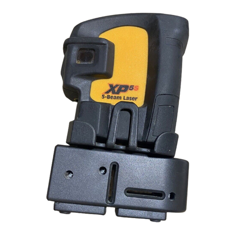
CST/BERGER
CST/BERGER XP5S Assembly instructions
CST/BERGER
CST/BERGER LM800DP User manual
CST/BERGER
CST/BERGER DGT 10 User manual

CST/BERGER
CST/BERGER LASERMARK 58-iLMXL User manual
CST/BERGER
CST/BERGER Lasermark LD500 User manual
CST/BERGER
CST/BERGER XP5 User manual
CST/BERGER
CST/BERGER AL-Series User manual
